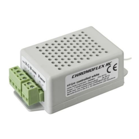
Barthelme CHROMOFLEX RC User manual

GEBRAUCHS-
ANWEISUNG
FÜR DEN
CHROMOFLEX
RC
BITTE AUFMERKSAM LESEN UND
AUFBEWAHREN!
2. BESTIMMUNGSGEMÄSSE
VERWENDUNG
Das Steuergerät ist für trockene Innen-
räume konzipiert; aufgrund seiner Bauart
können sich die LEDs aber auch (sofern
dafür geeignet) im Außen- oder Feuchtbe-
reich befinden.
Das Steuergerät darf nur mit einer an die
LEDs angepassten Stromversorgung be-
trieben werden. Andere Verbraucher als
LEDs (insbesondere induktive Verbraucher,
wie etwa Motoren oder Drosseln können
das Gerät zerstören).
Chromoflex RC Mini Stripe verwendet die
in der EU, Schweiz, Norwegen und Island
lizenzfreie Funkfrequenz 868,3 MHz.
3. SICHERHEITSHINWEISE
Das Gerät erzeugt beim Betrieb Wärme.
Auf ausreichende Luftzirkulation muss
geachtet werden.
Das Modul verfügt intern über einen Ver-
polungsschutz (mit begrenzter Leistungs-
fähigkeit), trotzdem kann Verpolung (auch
kurzzeitiges) das Gerät zerstören.
Beim nicht bestimmungsgemäßen Be-
trieb, Verpolung, bei Umbau des Gerätes,
bei Sach- oder Personenschäden, die
durch unsachgemäße Handhabung oder
Nichtbeachten der Sicherheitshinweise
verursacht werden, übernehmen wir kei-
nerlei Haftung und der Garantieanspruch
erlischt.
Sofern sich die LEDs im Feuchtbereich
(z.B. Schwimmbäder, Sauna, etc.), befin-
den, ist besonders auf die geltenden Vor-
schriften bezüglich der Stromversorgung
zu achten. Die Installation des Produktes
darf nur durch eine qualifizierte Fachkraft
erfolgen, die mit den geltenden Vorschrif-
ten (z.B. DIN, VDE, EN) vertraut ist.
Dieses Produkt ist kein Spielzeug und ge-
hört nicht in Kinderhände! LEDs können
sehr heiß werden! Es ist in jedem Fall rat-
sam, die vorgegebene Maximaltemperatur
der Leuchtmittel nicht zu übersteigen, da
sich dies nachhaltig auf Lebensdauer und
Lichtintensität der LEDs auswirken kann.
4. LIEFERUMFANG
UND WEITERE INFORMATIONEN
Jedes Chromoflex RC Mini Stripe Modul
wird mit dieser Anleitung, den passen-
den Gegensteckern für Stromversorgung
und LEDs geliefert.
Die Funkfernsteuerung und der
USB-Dongle (für PC) sind optionales Zu-
behör.
WICHTIG:
Sämtliche Anleitungen zu Chromoflex
sind frei per Internet herunterladbar, Ad-
resse am Ende dieser Anleitung.
WARNUNG 1:
LEDs können, selbst im gedimmten Zu-
stand, sehr hohe Lichtintensität entwi-
ckeln! Manche LEDs fallen sogar unter die
Laser-Klassifizierung. Speziell in Verbin-
dung mit Optiken können selbst schwache
LEDs sehr gefährlich werden. Der direkte
Blick in LEDs kann irreparable Schäden an
der Netzhaut des Auges hervorrufen. Ver-
wenden Sie Diusoren zur Lichtstreuung.
WARNUNG 2:
Bitte beachten Sie, dass LED Licht seine
Intensität sehr schnell wechseln kann.
Schnell wechselnde Lichteekte können
die Wahrnehmung beeinflussen oder Be-
schwerden hervorrufen oder Anfälle bei
Personen mit Neigung zu Epilepsie aus-
lösen.
Nahezu beliebig viele Module können per
Funk miteinander vernetzt werden, der
gleichzeitige Betrieb von 8 verschiedenen
Netzen ist möglich. Innerhalb eines Netzes
sind sämtliche Farbwechsel automatisch
synchron (die Zufallseekte jedoch nicht).
So lassen sich mit minimalem Aufwand
anspruchsvolle Aufgaben erledigen. Die
Reichweite hängt stark von den räum-
lichen Gegebenheiten ab. Im freien Feld
sind bis zu 300 Metern möglich; im Innen-
bereich ist normalerweise ein zuverlässi-
ger Betrieb über 20-50 Meter problemlos.
FARBLICHT-STEUERUNG
MIT FUNKFERNSTEUERUNG
Der Chromoflex RC Mini Stripe ist ein
preiswertes Steuergerät für Eektbe-
leuchtung mittels moderner Hochleis-
tungs-LEDs. Es können bis zu 16 Mio. Far-
ben erzeugt werden. Chromoflex RC Mini
Stripe eignet sich ideal für anspruchsvolle
Eekt- und Farblichtbeleuchtung im De-
korations- und Wellness-Bereich. Durch
seine kompakten Abmessungen (34 mm x
19 mm x 17 mm) ist er ideal für den Ein-
bau in schwer zugängliche Bereiche oder
Leuchtengehäuse. Desweiteren ist auch
eine vergossene Version für den Einbau in
Feuchträumen erhältlich. Die vergossene
Version ist werkseitig auf Netz 8 vorein-
gestellt. Diese Voreinstellung kann nicht
geändert werden.
Art.-Nr. 6600036X
Der Chromoflex RC ist eine Weiterentwick-
lung von Chromoflex I und II. Die Version
RC erhält sämtliche Steuersignale per
Funk. Zur Steuerung und Einstellung
werden daher entweder die Chromoflex
Fernbedienung oder der Chromoflex USB
Dongle (für PC) benötigt.
Der Chromoflex RC Mini Stripe wurde so
konstruiert, dass auch ohne Programmie-
rung anspruchsvolle Beleuchtungsauf-
gaben im Dekorations- und Wellness-Be-
reich gelöst werden können. Die Geräte
enthalten werksmäßig bereits eine Anzahl
von Lichteekten, von festen Farben über
beruhigende Wellness-Farbwechsel bis
zur Show-Beleuchtung. Per Funk können
diese teilweise verändert oder als Stan-
dard-Eekte gespeichert werden.

5. ANSCHLÜSSE LEDS | TRAFO
WICHTIG: Die Stromversorgung muss auf
die verwendeten Leuchtmittel abgestimmt
sein!
WICHTIG: Wir liefern auch zu den Modellen
passende Leuchtmittel! Unsere Leucht-
mittel sind mit entsprechenden Steckern
versehen. Ebenso sind bei uns geeignete
Stromversorgungen erhältlich.
WICHTIG: Eine ungeeignete Stromversor-
gung kann zu Funktionsstörungen, uner-
wünschtem Flackern, Zerstörung der LEDs
oder Elektronik oder im schlimmsten Fall
zu Überhitzungen führen.
Wir raten dringend von der Verwendung
von unstabilisierten Billig-Netzteilen ab!
Und empfehlen in jedem Fall Stromversor-
gungen in Schaltnetzteil-Technologie!
Eine Stromversorgung kann natürlich
auch mehrere Module gleichzeitig speisen.
In diesem Fall ist auf ausreichende Leis-
tung der Stromversorgung zu achten.
Die Module sollten mit mindestens 7,5 Volt
versorgt werden, die maximal zulässige
Spannung ist 26 Volt (+ 5 %).
6. MODELL „MINI STRIPE“
Dieses Modell verfügt über keine Strom-
begrenzung. Es gibt die Versorgungs-
spannung direkt an die Leuchtmittel (die
üblicherweise LED Streifen sind) weiter.
Wenn also der LED Streifen 12 Volt be-
nötigt, muss auch dies die Spannung des
Netzteils ein.
Hinweis: In der Praxis sind LED Streifen
mit 10 Volt, 12 Volt und 24 Volt üblich.
LED Streifen können teilweise, je nach
Länge, sehr hohe Ströme benötigen.
HINWEIS ZU UNSEREN LED-STREIFEN:
Von uns gelieferte LED-Streifen sind üb-
licherweise auf Rollen mit maximal ca.
4 Meter Länge, der Stromverbrauch ist
etwa 2 Ampere bei 12 Volt pro Farbe.
Das Modell „Chromoflex RC Mini Stripe
kann bis zu 2 Ampere pro Kanal schalten
(also in der Summe bis zu 6 Ampere).
7. ERST-INBETRIEBNAHME
Über die beiliegenden Steckklemmen las-
sen sich Modul, Stromversorgung, etc. pro-
blemlos installieren. Nachdem Stromver-
sorgung und Leuchtmittel angeschlossen
worden sind, empfiehlt sich ein erster Test:
Nach Einschalten der Stromversorgung
sollte das Modul einen Farbwechsel, begin-
nend mit Rot, bestehend aus 8 Farben, jede
mit einer Standzeit von ca. 5 Sekunden und
einem weichen Wechsel (2,5 Sekunden)
durchlaufen.
Diagnose LED: Auf dem Modul befindet
sich eine Diagnose LED. Diese muss im re-
gulären Betrieb exakt jede Sekunde wech-
seln. Bei Datenübertragung flackert sie.
8. WERKSPROGRAMME |
FARBTABELLEN
Bei Auslieferung enthalten die Module 12
Eekte: 3 Farbwechsel, 3 Benutzerpro-
gramme, 5 Zufallseekte, 1 änderbare
Farbtabelle mit 8 Farben, 20 Festfarben.
Mehr Details dazu, finden sich in der An-
leitung zur Fernbedienung und in der An-
leitung zur Software für den USB-Dongle
(für PC).
230 V ~ 12 V | 24 V - Antenne
Rot, LED-Streifen, z.B. 4 Mtr, 2 A
Grün, LED-Streifen, z.B. 4 Mtr, 2 A
Blau, LED-Streifen, z.B. 4 Mtr, 1,8 A
CHROMOFLEX MINI
R-
G-
B-
Gemeinsamer +
Versorgung+
Versorgung- (GND)
Trafo
230 V
12 V|24 V - 6A

In der Zeichnung sind ein einziges Mo-
dul und die Fernbedienung auf „Master“
gesetzt. Somit kann nur der Master auf
die Fernbedienung reagieren. Der Mas-
ter sendet seine Einstellungen perio-
disch an alle anderen Module.
Daher spielt es auch keine Rolle, wenn
ein Modul nachträglich eingeschaltet
wird: Spätestens nach ein paar Sekun-
den erhält es vom Master dessen Ein-
stellungen und dessen Zeitbasis.
Die Fernsteuerung erwartet vom Master
eine Antwort, der Master selbst erwar-
tet aber von den anderen Chromoflex RC
Mini Stripe im Netz keine Antwort, da
dieses Signal alle paar Sekunden wie-
derholt wird. Sollte ein Modul ein Signal
(wegen Störungen oder anderen Gerä-
ten) einmal nicht bekommen, so spielt
dies keine Rolle.
Es bietet sich an, ein Modul in der Mitte
des Netzes als Master zu wählen. Soll-
te eines der anderen Module zu weit
entfernt sein, merkt man sehr schnell,
wenn es auf die Fernbedienung (über
den Master) nur unzuverlässig oder gar
nicht reagiert. Mehrere Master pro Netz
sind nicht sinnvoll.
Anmerkung zur Reichweite:
Die Fernbedienung verwendet eine
(schwächere) interne Antenne als der
Chromoflex RC Mini Stripe Module oder
der USB-Dongle. Die Reichweite der
Fernbedienung ist daher geringer als
z.B. die des Masters zu den anderen
Modulen. Beim Einbau der Chromoflex
RC Mini Stripe Module sollte bei Bedarf
drauf geachtet werden, dass die An-
tennen der Chromoflex RC Mini Stripe
Module möglichst „in die Luft“ schau-
en. Abschirmungen in unmittelbarerer
Nähe zur Antenne (Metall, Stein, Beton)
können Funksignale stark schwächen.
Bei schlechten Funksignalen hilft es oft
schon, die Lage des Moduls um einige
Zentimeter zu verändern.
Hier: Alle Geräte auf Netz 8
(= Werkseinstellung)
Fernbedienung
(gesetzt auf MASTER-Betrieb)
WICHTIG:
Ein MASTER wird nur bei mehreren
Modulen pro Netz benötigt.
1234
Chromoflex RC
ON
MASTER: DIP4 = ON
1234
Chromoflex RC
ON
NORMAL: DIP4 = OFF
1234
Chromoflex RC
ON
NORMAL
1234
Chromoflex RC
ON
NORMAL
1234
Chromoflex RC
ON
NORMAL
9. VERNETZUNG UND FUNKFERNSTEU-
ERUNG
Die für die Funkübertragung verwen-
dete Frequenz (868,3 MHz) wird auch
von anderen Geräten (Funksteckdosen,
Fernbedienungen, etc.) verwendet, ein
störungsfreier Betrieb aller Geräte ist
aber trotzdem gewährleistet (die gelten-
den Vorschriften regeln dies exakt). Für
eine zuverlässige Datenübertragung
wird daher beim Chromoflex RC Mini
Stripe ein bidirektionales System ver-
wendet, d.h. die Fernbedienung oder der
USB-Dongle erwarten vom Chromoflex
RC Mini Stripe eine Antwort!
Im einfachsten Fall wird nur ein einzel-
nes Modul betrieben: Die Fernbedienung
oder der USB-Dongle (für PC) muss
daher nur mit einem einzigen Modul
kommunizieren: Hier muss lediglich auf
beiden Seiten das gleiche Netz (1-8) ein-
gestellt werden.
Dieser Modus (Einzel-, bzw. Normalbe-
trieb) auf Netz 8 ist voreingestellt (Werk-
seinstellung).
Befinden sich mehrere Chromoflex RC
Mini Stripe im selben Netz, so sollen
alle festen Farben und Verläufe mitein-
ander synchron laufen. Daher kann per
DIP-Schalter für ein einziges Modul in
diesem Netz der „Master“-Modus ak-
tiviert werden: Ein „Master“ gibt peri-
odisch (alle paar Sekunden) seine Ein-
stellungen an andere Module desselben
Netzes weiter:

10. DIP-SCHALTER
NUR BEI UNVERGOSSENEM MODELL
66000361
Das verwendete Netz und der Master-Mo-
dus können per DIP-Schalter geändert
werden. Dazu befindet sich im Inneren des
Moduls ein 4-poliger DIP-Schalter. Nach
dem Önen des Moduls ist dieser sichtbar
(Belegung siehe unten).
Wichtig: Bitte keine der Elektronik-Bautei-
le berühren, da diese durch Elektrostatik
Schaden nehmen könnten. Es ist ratsam,
zum Umlegen der DIP-Schalter etwas
Spitzes, nicht elektrisch Leitendes zu ver-
wenden.
Wichtig: Sämtliche Änderungen an den
DIP-Schaltern werden erst nach einem
Neustart (Anlegen der Versorgungsspan-
nung) wirksam!
12. DIP-SCHALTER-BELEGUNG
11. TECHNISCHE DATEN
Betriebsspannung:
7,5 - 26 Volt (+ 5 %), stabilisiert. Wichtig:
Die Stromversorgung muss über entspre-
chende Puls-Belastbarkeit verfügen. Un-
stabilisierte oder zu schwache Netzteile
können Flackern bei Farbübergängen
hervorrufen.
Eigenstromverbrauch (ohne Leuchtmittel):
ca. 10 - 20 mA
Umgebungstemperatur:
0 °C - max. + 50 °C (empfohlen <= 30 °C)
(Betrieb nur in trockenen Innenräumen
mit ausreichender Luftzirkulation zur
Wärmeabfuhr)
Funkfrequenz:
868,3 MHz (lizenzfrei in der EU, Schweiz,
Norwegen und Island).
NOTIZEN
KONTAKT
Josef Barthelme GmbH & Co. KG
Oedenberger Str. 149
90491 Nürnberg | Germany
T: +49 911 42 476 0
www.barthelme.de
Modulations-System:
Die Chromoflex-Module verwenden die
Vektor-Fraktal-Modulation („VFM“) zum
Erzeugen der Lichtmischung. Die VFM ist
ein digitales Modulationsverfahren, das
u.a. Stromversorgungen deutlich weniger
belastet als traditionelle Systeme. Die
Modulationsfrequenz liegt im Bereich von
etwa 120 - max. 240 Hz. Zum Patent an-
gemeldet.
Modell „Chromoflex RC Mini Stripe“
Gepulste Konstantspannung, maximal
zulässiger Strom 2 Ampere pro Kanal (3
Kanäle).
TECHNISCHE ÄNDERUNGEN
VORBEHALTEN.
STAND 06|2016
ANMERKUNG:
DIE ERWÄHNTEN DIP-SCHALTER
BEZIEHEN SICH NUR AUF DAS UNVER-
GOSSENE MODELL 66000361!

INSTRUCTION
MANUAL
FOR
CHROMOFLEX
RC
PLEASE READ THIS MANUAL CAREFULLY
AND KEEP IT IN A SAVE PLACE!
WIRELESS FULL-SPECTRUM-
COLOUR-CONTROL
Chromoflex RC mini stripe is an excel-
lent value full colour control and was
designed for use with modern high-po-
wer RGB LEDs. The Chromoflex RC mini
stripe is able to synthesise up to 16 mil-
lions of dierent colours. Hence, it is the
ideal control for all kinds of sophisticated
eect illuminations, deco and wellness
lighting. Due to its compact dimensions
(27 mm x 19 mm x 17 mm), it is ideal for
installation in dicult-to-access-areas or
luminaire housings. Additionally a fully
encapsulated version is available for use
in humid environments. The encapsula-
ted version is set to net 8 by default. This
setting cannot be changed.
Chromoflex RC mini stripe is an enhance-
ment of ChromoFlex I and II. Chromoflex
Item no. 6600036X
RC mini stripe receives all commands by
radio control. Therefore, for controlling
and alignment, either the ChromoFlex Re-
mote Control or USB dongle is needed.
The Chromoflex RC mini stripe was desi-
gned for easy use. It is equipped with many
built-in eects (from calming colour chan-
ge, up to show eects). However, the user
can change and store many own settings.
Up to 8 dierent wireless networks can be
operated simultaneously. Within one net
all colour changes will run synchronous
automatically with the exception of ran-
dom eects. The range of the radio trans-
mission is depending on the environment,
but can be up to 300 metres in open air.
Indoors a reliable operation within 20-50
metres normally is no problem.
2. USAGE
The modules were designed for in-house
use in dry places, but the LEDs (if suited)
might also be used in wet environments
or outdoor.
Important: The modules must be operated
with a power supply which is matched to
the used LEDs! Non-LED loads (especial-
ly inductive loads like motors, coils, etc)
might destroy or damage the module.
Chromoflex RC mini stripe operates on a
frequency of 868.3 MHz (licence-free in EC,
Switzerland, Norway and Iceland)
3. SAFETY INSTRUCTIONS
The modules might produce some heat.
Care must be taken to provide unrestric-
ted air ventilation.
The ChromoFlex is equipped with a built-
in protection against reverse polarity.
Connecting the power in reverse polarity
can destroy the module, even if connected
for a short time only.
We decline any liability, loss, or damage
caused by improperly used modules! Gu-
arantee is also lost in such cases.
Important: Electronics must not be mo-
dified. Observe the ocial regulations for
electrical devices (like DIN, VDE, EN), espe-
cially when LEDs are used in wet areas!
This product is not a toy; keep away from
children!
LEDs can get quite hot. We strongly re-
commend ensuring maximum operating
temperature is not exceeded, because this
might reduce the expected lifetime of the
LEDs significantly.
4. CONTENTS
Each ChromoFlex is shipped with this
short manual and connectors for power
supply and LEDs.
The remote control (Part No: 66000062)
and the USB dongle (Part No: 66000063)
are optional accessories.
For programming the software
´ChromoFlex Colour Editor´ is free for
download from our website (address
at the end of this manual). It will run on
any PC available with Windows 98SE,
Windows XP, Vista and higher (all trade-
marks of Microsoft Corp.).
WARNING 1:
LED light may have very high intensity
even when dimmed. Some modern LEDs
are classified by the lasers marking ob-
ligation. Particularly in connection with
optics also weak LEDs may be very dan-
gerous. Staring into LEDs may cause irre-
parable damage to the eye‘s retina. Hence:
NEVER STARE INTO THE BEAM. Use diu-
sers to spread the intensity!
WARNING 2:
Please be aware of the fact that LED light
may cause side eects. This light changes
intensity very fast! Changing light may
aect the perception and is also known to
trigger epileptic seizures in persons who
are photosensitive.
However, the user can change and store
many own settings. Up to 8 dierent wi-
reless networks can be operated simul-
taneously. The colour changes and static
colours of the modules within a network
are synchronised automatically (but ran-
dom eects of course not). The range of
the radio transmission is depending on the
environment, but can be up to 300 meters
in open air. Indoors a reliable operation wi-
thin 20-50 meters normally is no problem.

5. CONNECTING THE LEDS |
POWER SUPPLY
IMPORTANT: The module must be opera-
ted with a power supply which is suitable
for the used LEDs!
IMPORTANT: Improper power supplies
may lead to malfunctions and unwan-
ted flickering eects or overheating. We
strongly recommend using high-quality
(stabilised) switching power supplies!
One power supply can be used for seve-
ral ChromoFlex modules in parallel if the
maximum output power of the supply is
observed.
The minimum voltage for correct operation
is 7.5 volts; maximum voltage is 26 volts
(+ 5 %).
6. MODEL
„CHROMOFLEX RC MINI STRIPE “
This model does not have any internal
current regulator. The supply voltage is
passed through and the voltage of the
power supply must match with the volta-
ge of the LED stripe.
Regarding any possible voltage drop,
please see the previous paragraph. Cable
lengths of up to 5 meters are allowed.
Note: LED stripes of 10 volts, 12 volts and
24 volts are oered on the market. De-
pending on the cable length used, LEDs
might need very high currents.
Note: We also deliver flexible and rigid
LED stripes (on reels) with a length of up
to 324 centimetres. Each colour will draw
up to 2 amperes at 24 volts.
The model „STRIPE“ is able to switch up
to 2 ampere per channel (6 ampere in
total).
230 V ~ 12 V | 24 V - Antenna
Red, LED stripe, i.e. 4 Mtr, 2 A
Green, LED stripe, i.e. 4 Mtr, 2 A
Blue, LED stripe, i.e. 4 Mtr, 1,8 A
CHROMOFLEX MINI
R-
G-
B-
Common +
Power supply +
Power supply- (GND)
Power suplly
230 V
12 V|24 V - 6A
7. FIRST TEST
Installation is very simple when using the
connectors enclosed.
At first, a test is performed on the module
showing module a standard colour change
(this is the factory default). This eect con-
sists of 8 colours, each hold for 5 seconds;
colour transition time is 2.5 seconds. Diag-
nostic LED: The modules are equipped with
a small red LED. For regular operation this
LED will change every 2 seconds and fli-
cker when data is transmitted over the bus.
8. FACTORY SETUP |
COLOUR TABLES
By default, the module is shipped with 12
eects: 3 colour changes, 3 user eects,
5 random eects, 1 user colour table
with 8 colours and 20 fixed colours, More
details about this can be found in the ma-
nual for the handheld Radio Remote Con-
trol and in the manual of the Chromoflex
USB Dongle (for PC).

Even if other modules (non-“Master“)
are switched on later, they will recei-
ve (at least after a few seconds) the
settings from the Master. Even if other
modules, non-masters, are switched on
later, they will receive the settings from
the Master only a few seconds later. The
communication of the radio remote con-
trol or the PC dongle with the master is
2-way. The master itself sends signals
to the other modules only unidirecti-
onal. The data transmission protocol
is based on a mathematical algorithm
that is very robust against transmissi-
on errors. Communication between the
modules is safe, because if any packet
is lost, the next packet will follow after
a few seconds.
Even if many packets are lost, the net-
work will still work synchronously. It
proved eciently in practice to set a
module as master in the middle of the
network. If one of the other modules is
too far from the master, it will not follow
reliablely to the master’s commands.
Note about the range:
The radio remote control has a less
stronger antenna than the Chromoflex
RC modules or the USB dongle. Normal-
ly the range of the radio remote control
is below the range of the master to the
other modules. To achieve a good per-
formance, we recommend justifying that
the antenna of the Chromoflex RC mo-
dules is straight ´into the air´. However,
dense materials like stone, concrete and
metal parts may reduce the range signi-
ficantly, especially when close to the an-
tenna. In case of weak signal, it is quite
enough to move the modules only a few
centimetres next to each other.
Here: All modules set to Network 8
(= Factory default)
Radio Remote Control
(set to „Master“-Mode)
IMPORTANT:
A „Master“ is only if more than one modu-
les are in the same network.
1234
Chromoflex RC
ON
MASTER: DIP4 = ON
1234
Chromoflex RC
ON
NORMAL: DIP4 = OFF
1234
Chromoflex RC
ON
NORMAL
1234
Chromoflex RC
ON
NORMAL
1234
Chromoflex RC
ON
NORMAL
9. NETWORKING AND WIRELESS
OPERATION
The ChromoFlex RC mini stripe is wor-
king on a radio frequency of 868.3 MHz.
This frequency is often used for other
radio controls and wireless sensors.
Very strict regulations ensure that ope-
ration, free from interference, is possib-
le. Therefore ChromoFlex RC mini stripe
uses a bidirectional communication to
ensure reliable operation, meaning the
Remote Control or the USB dongle re-
quires an acknowledgement from the
ChromoFlex RC mini stripe.
A basic application is using one Chro-
moFlex RC mini stripe and either remote
control or USB dongle. Both units have
to be set on the same net. This is also
the default factory setup mode (default:
network 8).
With several ChromoFlex RC mini stripe
modules in one net, the colour changes
and the 12 programmes will run syn-
chronously. Within this net, a Master
Mode can be set for a single module by
using dip switches. It will forward its
settings (and time base) periodically to
all modules in the same net.

10. DIP-SWITCHES
ONLY FOR UNENCAPSULED MODEL
66000361
The selected Network and the Master
mode are set with a small 4-DIP switch on
top of the PCB.
Important: Please do not touch any of the
electronic components, because of the risk
of damage by electrostatic discharge. We
recommend using a small non-conducting
tool to change the DIP switches.
Important: Any changes of the DIP swit-
ches become active after a reset or power
on only!
12. DIP-SWITCH-CONFIGURATION NOTE:
THE MENTIONED DIP SWITCHES REFER
ONLY TO THE UNENCAPSULED MODEL
66000361!
11. TECHNICAL DATA
Power supply:
Power supply:
7.5 - 26 volt (+ 5 %), regulated. Important:
The power supply should have an equi-
valent pulse load. Unregulated or weak
power supplies may cause flickering or
malfunctions.
Module current (without LED lamps):
ca.- 20 mA
Operating temperature:
0 °C - max. + 50 °C (recommended: <= 30
°C) (Use only in dry places with sucient
air ventilation)
Radio frequency:
868.3 MHz (licence-free in EC, Switzerland,
Norway and Iceland)
NOTES
Modulation system:
The Chromoflex modules are based on a
digital system, named „Vector-Fractal-Mo-
dulation“ or „VFM“. This modulation sys-
tem was optimised for minimising load on
power supplies and has considerable ad-
vantages compared to traditional systems.
The modulation frequency is in the range
from 120 Hz up to (max.) 240 Hz. Patent
pending.
Model „Chromoflex RC Mini Stripe“
Pulsed constant voltage, maximum cur-
rent allowed: 2 ampere per channel (3
channels)
CONTACT
Josef Barthelme GmbH & Co. KG
Oedenberger Str. 149
90491 Nuremberg | Germany
T: +49 911 42 476 0
www.barthelme.de
SUBJECT TO TECHNICAL
CHANGES.
VERSION 06|2016
Other manuals for CHROMOFLEX RC
3
This manual suits for next models
1
Table of contents
Languages:
Other Barthelme Controllers manuals
Popular Controllers manuals by other brands

ICP DAS USA
ICP DAS USA I-7188XC quick start guide

M-system
M-system EAR70 instruction manual

Progeny
Progeny P1 Stand Alone manual

JORDAN CONTROLS
JORDAN CONTROLS SM-1715 instruction manual

LAE
LAE LTR-5 Series Instructions for use

Hans Grohe
Hans Grohe iBox Hub 25020180 Assembly Instruction and instructions for use

Linak
Linak DL12 user manual

Honeywell
Honeywell HON 670 Component documentation, Maintenance manual and spare parts

Colorlight
Colorlight Z6 Super Controller user manual

AMX
AMX NX-1200 WEBCONSOLE AND PROGRAMMING GUIDE

NyQuest Innovation Labs
NyQuest Innovation Labs iCON manual

AUMA
AUMA SEVEN 2SA7 Technical data