Progeny P1 Stand Alone User manual

Document Number: MAN0045 Issue: 4.01 Page 1of 16
P1 Stand Alone Controller Manual
(Bitesize)

Document Number: MAN0045 Issue: 4.01 Page 2of 16
SAFETY NOTES
Please read this manual carefully before attempting to install, program or operate the Progeny Access Control
P1 STAND ALONE equipment.
This equipment must be installed in line with all relevant regulations and standards.
Make sure that wiring is rated according to fuses and current limits of relevant power supplies.
Apart from the mains supply all connections to this unit must be SELV level. (Safety Extra Low Voltage, BS EN
60950 1992)
No users should access the inside of the control box. The control box contains hazardous voltages and access is
limited to qualified personnel only. All user-programming for the controller is either done at one of the keyboards
or at the PC.
Every effort is made to ensure that this manual is complete and free from errors. However we reserve the right to
make changes to these products and this manual without notice.
No liability is accepted for loss damage or injury as a consequence of using these products or instructions.
MOUNTING
The optimum location for the controller depends on the application. As a general Guide:
Always mount the control equipment on the secure side of the door.
Mount as close as possible to the door(s) to be controlled (less than 100m).
Offer the opened back of the enclosure up to the wall where the unit is to be mounted and mark the location of
the fixing dimples on the wall. Drill and plug the wall. Bring in mains supply and other cables that are to enter
via the rear cable access holes. Screw the controller to the wall.
WARNING: Extreme caution must be used when opening the controller housing. DO NOT touch any
connections or components other than the reset button. Avoid touching any of the terminations with a
metal object such as a wristwatch or jewellery.
POWER
The Progeny P1 STAND ALONE controller should be connected to a 24 Hour 220/240V mains supply. Ideally
a fused spur should be used for this purpose. The cable used to connect the mains supply should be 0.75 to
2mm2. A fused terminal block is provided for mains. Observe the polarity when making these connections.
When designing an access control system it is important to make sure that the power supply is not
overloaded. The built in power supply of the Progeny P1 STAND ALONE controller is capable of providing
power for most standard applications. However, there may be situations where additional power supplies are
required. These notes are intended to help you determine when this is the case.
Each enclosure can house one or two door controllers. The 5A PSU in the enclosure supplies 2A at 12V
(13.8V) to each controller channel.
IMPORTANT: If a battery is to be fitted then it must be of the correct type. The power supply is designed to
charge sealed lead acid batteries. Do not connect NiCad or Dry Cell batteries or any other chemistry.
Power up sequence should be: Mains first then Battery
Power down sequence should be: Battery first then Mains
The current drawn from the power supply falls into three main categories:
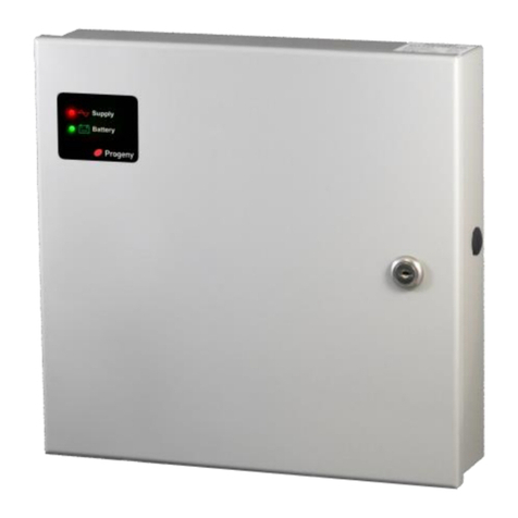
Battery
Supply
Indicates Connection
and Status of the
Main Supply
Indicates Connection and
Charge Status of Battery

Document Number: MAN0045 Issue: 4.01 Page 3of 16
Supply current for internal electronics and charging batteries.
Lock Loads (Magnets, Strikes etc.)
Auxiliary loads. (Readers, Keyboards, Indicators & Sounders)
P1 STAND ALONE CONTROLLER MODULES
In the case of the 4001M and 4002M Modules supplied as components, the power is supplied via the two way
terminal block on the Keyboard Module. The Supply to this should be in the range 11 to 14V DC and be able
to supply 2.0 A. The cables should be 16/0.2 minimum or rated at 2.0A DC
CONNECTING 24V LOCKS
To operate a 24V lock a customer supplied 24V PSU will be required. Either the lock output can be used to
drive the coil of a clean contact relay which in turn can be used to switch a 24V supply or, if not being used
for another function, Relay B of the P1 STAND ALONE controller can be used to switch the 24V supply. If
following the latter, it is important to ensure that Relay B is set to follow the Lock relay (factory default setting).
INDICATORS
Status LEDs can be found on the front panel of the controller and repeated at the keyboard and card readers.
These indicators have the following meanings:
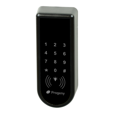
Keypad Status LED
Meaning
Off
Normal
On
Lock released
Flashing
Programming Mode
SOUND
Sound is used to give the user additional feedback
on the status of the controller and progress during
Programming.
Sound
Meaning
Continuous Two Tone, High Volume
Failed to Close (PDO) Alarm
Four Notes “Low – High –Low –High”
Programming Mode
Two Notes “Low – High”
Confirm Programming Change
Two Notes “High – Low “
Programming Error
Single Short Note “High”
Keyboard Key Push
3 long Beeps
Card not Registered (No Card Pack)
4 short
Card Registered but not enabled.
Tic Tic Tic
Memory Programming in progress
Note: The sounds from the keyboard controller can be annoying if located in earshot. To mute the on-board
sounder, press #& 5together. However the sounder will re activate when the * key is pressed.
READER “A” & “B” LED’s
Meaning
Off
Normal
On
Lock released
2 Flashes
Anti-pass back
3 Flashes
Unknown Card / Fob
4 Flashes
Invalid card
5 Flashes
Card out of valid period
6 Flashes
Access level OTL
7 Flashes
Reader Error

Document Number: MAN0045 Issue: 4.01 Page 4of 16
CONTROLLERS
TWO DOOR VERSION
The "two door" version simply contains
two access controllers in one enclosure.
Both controllers can be programmed
from the keyboard but first the user
needs to choose which controller to
programme.
To select control panel A (or door 1) press the [#] and [1] key
together. The controller will beep and the ‘Door ‘A’ green
selected’ LED will illuminate.
To select control panel B (or door 2) press the [#] and [2] key
together. The controller will beep and the ‘Door ‘B’ green
selected’ LED will illuminate.
ONE DOOR VERSION
The single door version contains only one controller and
therefore, the indicators for Door B are not needed. These
indicators are included in case the unit is ever up-graded to
two doors. Before programming, make sure that the
‘SELECTED’ indicator for Door A is illuminated. If not press
[#] and [1] keys together. The controller will beep and the
‘Door ‘A’ selected’ LED will illuminate.
UNLOCKING THE KEYBOARD
To unlock the keyboard for programming first press * and #.
The keyboard will not accept any input until it is enabled.
PROGRAMMING
Programming is achieved by entering a password at the keyboard followed by a menu selection code. There
are two programming menus, one for the USER and one for the ENGINEER. Each menu has a separate six-
digit password. Depending on the menu option selected, configuration data can then be entered at the
keyboard.
40027
40028

Document Number: MAN0045 Issue: 4.01 Page 5of 16
P1 STAND ALONE CONTROLLER
40027
Reset Push Button
Interlock
Keyboard
Signals
Inputs
Outputs
Relay B
Lock O/P
Reader A
Reader B
BCD
Keyboard
0V to Earth Link
Lock Supply
Terminal
Controller Status LED

Document Number: MAN0045 Issue: 4.01 Page 6of 16
USER MENU
The User Menu is access by entering * followed by the User Password. The default for this is 654321.
Users Menu #
Description
Default Value
* 00
User Password
6 5 4 3 2 1
* 01
Access Code
None
* 02
Discover Presented Cards
-
* 03
Forget Presented Cards
-
* 04
Add Card by Number
-
* 05
Remove Card by number
-
USER PASSWORD
Passwords are the means by which the
systems operator gains access to the
Programming functions. This is a 6-digit
number and can be changed by using the
following procedure.
Changing the user password
This example shows the password
changed to 234567.
Default Value:
654321
The factory default can be restored by a
“Full Reset” or by connecting the PWR
input to 0V for 4 seconds.
Related Engineers Menus:
00 “Engineers Password”
ACCESS CODE FUNCTIONS
The P1 Stand Alone controller has a single
access code that can be programmed. The
access code can be any number of digits
from 1 to 8. The access code is only active
when the keyboard is in:
Normal Keyboard Mode
Card & Code Mode
See Engineers Function 20 for more details
If more than one access code is needed
see “Virtual Card” modes for the keyboard.
REMOVING ACCESS CODES
Engineers’ function 98 will erase the
access code.
Status LED will Flash
Enter User Password
* 6 5 4 3 2 1
Single Access Code * 0 1
Status LED will stop Flashing
Complete & Exit Programming Mode
#
Enter the required Access Code 1 2 3 4
Status LED will Flash
Enter User Password
* 6 5 4 3 2 1
Select User Passwordmenu * 0 0
Status LED will stop Flashing
Complete & Exit Programming Mode
#
Enter the new Password 2 3 4 5 6 7
Enter the new Password again 2 3 4 5 6 7

Document Number: MAN0045 Issue: 4.01 Page 7of 16
CHANGING ACCESS CODES BY KEY SWITCH
1. Turn key switch on
2. Enter new access code.
3. Turn key switch off

Document Number: MAN0045 Issue: 4.01 Page 8of 16
ADDING CARDS by PRESENTATION (DISCOVER)
User function 02
Make sure you have the correct reader
technology selected for the readers that
are connected before using this function.
All cards presented to the reader will be
remembered and given access.
Related User Menus:
03 “Forget Cards”
04 “Add Card”
05 “Disable Card”
Related Engineers Menus:
04 “Reader A Technology”
05 “Reader B Technology”
20 “Keyboard Mode”
11 “Random Search
20 “Keyboard Mode”
31 to 36 “Feedback Volume Control”
REMOVING CARDS by
PRESENTATION (FORGET)
User function 03
This is the reverse of the Discovery Mode.
The cards presented to the reader will be
removed from memory and will report as
“Unknown Card” if access is attempted.
If you simply need to disable a card use
menu function 5.
Status LED will Flash
Enter User Password
* 6 5 4 3 2 1
Status LED will stop Flashing
Complete & Exit Programming Mode
#
Forget Card Menu * 0 3
Present Cards one after another Present Card
Status LED will Flash
Enter User Password
* 6 5 4 3 2 1
Discover Card Menu * 0 2
Status LED will stop Flashing
Complete & Exit Programming Mode
#
Present Cards one after another Present Card

Document Number: MAN0045 Issue: 4.01 Page 9of 16
ADDING CARDS by NUMBER
Adding or enabling credentials by entering can be useful when the credentials themselves are not available or
if a large number of credentials need to be
added.
Single card:
Note that some cards have a serial number
printed on them. This should be used with
the cross-reference list, provided with
cards, to determine the actual card
number.
This example will enable a single card
numbered 80230001.
Block of cards
The quickest way to enable a whole group
of cards is to use the block add method
shown in this flow diagram.
This example will enable 50 cards, Site
code 8023 from card 0001 to 0050.
Related User Menus:
02 “Discover Cards”
03 “Forget Cards”
05 “Remove Card”
Related Engineers Menus:
04 “Reader A Technology”
05 “Reader B Technology”
11 “Random Search
20 “Keyboard Mode”
31 to 36 “Feedback Volume
Control”
Status LED will Flash
Enter User Password
* 6 5 4 3 2 1
Select Add Card IDMenu * 0 4
Enter Card ID 8 0 2 3 0 0 0 1
Status LED will stop Flashing
Complete & Exit Programming Mode
#
Status LED will Flash
Enter User Password
* 6 5 4 3 2 1
Select Add Card IDMenu * 0 4
Enter Quantity ( 1 to 9999 ) 50
Status LED will stop Flashing
Complete & Exit Programming Mode
#
Enter Card ID 8 0 2 3 0 0 0 1
Enter *as a separator *

Document Number: MAN0045 Issue: 4.01 Page 10 of 16
DISABLING CARDS by NUMBER
Single card
If a card is reported lost or stolen, the card
can be disabled to remove the security risk
without affecting any other card users.
Block of cards
The quickest way to disable a whole group
of cards is to use the “block add”method
shown in this flow diagram.
This example will disable 50 cards, Site
code 8023 from card 0001 to 0050.
Related User Menus:
02 “Discover Cards”
03 “Forget Cards”
04 “Add Card”
Related Engineers Menus:
04 “Reader A Technology”
05 “Reader B Technology”
20 “Keyboard Mode”
11 “Random Search”
20 “Keyboard Mode”
31 to 36 “Feedback Volume
Control”
Status LED will Flash
Enter User Password
* 6 5 4 3 2 1
Select Disable Card IDMenu * 0 5
Enter Quantity ( 1 to 9999 ) 50
Status LED will stop Flashing
Complete & Exit Programming Mode
#
Enter Card ID 8 0 2 3 0 0 0 1
Enter *as a separator *
Enter Card ID
Select Disable Card IDMenu
Status LED will Flash
Enter User Password
* 6 5 4 3 2 1
* 0 5
Status LED will stop Flashing
Complete & Exit Programming Mode
#
8 0 2 3 0 0 0 1

Document Number: MAN0045 Issue: 4.01 Page 11 of 16
ENGINEERS’MENU
Engineers Menu #
Description
Range
Default Value
* 00
Password
000000 to 999999
1 2 3 4 5 6
* 01
Delay to Lock Release
0 to 99 Sec
0
* 02
Lock Release Duration
0 to 99 Sec
3
* 03
PDO Time
0 to 99 Sec
0 = Off
* 04
Reader A technology
0 to 99
0 (Crystal 4 Wire)
* 05
Reader B technology
0 to 99
0 (Crystal 4 Wire)
* 06
Duress
1= On, 0 =Off
Off
* 07
Relay “B” mode
0 to 12
0 (follow relay A)
* 08
Timer for “B” relay
0 to 99 Sec
3
* 09
Penalty Time
0 to 99 Sec
0
* 10
Hacker Count
0 to 99
5
* 11
Random Search Rate
0 to 99
0 (Off)
* 12
Unlock Time Zone
0 to 64 (250)
65
* 14
Lock Drive Mode
0 to 4
0 (Relay Only)
* 15
Auto Relock on Door Close
1= On, 0 =Off
0 (Off)
* 19
External keyboard * mode
0 to 1
1 (Enter Prog)
* 20
Keyboard Mode
0 to 8
0 (Access Code)
* 25
Reader A APB Configuration
0 to 3
0
* 26
Reader B APB Configuration
0 to 3
0
* 27
Relay B Time Zone
0 to 64 (250)
65
* 28
2nd Stage Delay
0
0
* 29
Network Transmit Delay
0 to 99
10
* 30
Controller Mode
1 to 4
3 (P3 Legacy)
* 31
Alarm Sound Volume Controller
0 to 15
15
* 32
Feedback Volume Controller
0 to 15
8
* 33
Alarm Volume Reader A
0 to 15
15
* 34
Feedback Volume Reader A
0 to 15
8
* 35
Alarm Volume Reader B
0 to 15
15
* 36
Feedback Volume Reader B
0 to 15
8
* 40 to 54
Custom Reader Template A
-
-
* 60 to 74
Custom Reader Template B
-
-
* 56
Prefix code for reader A
0000 to 9999
0000
* 76
Prefix code for reader B
0000 to 9999
0000
* 98
Clear Access Code
-
-
* 99
Reset User Password
-
654321
For a detailed description of all these functions see the full version of this manual.

Document Number: MAN0045 Issue: 4.01 Page 12 of 16
READER A & B TECHNOLOGY
The reader technology code allows different types of card readers and cards to be used. Each card reader
input can have its own technology setting.
Code
Template
Notes
0
Crystal Reader
Native P1 Stand Alone Bidirectional 4 wire Interface
1
ISO 15693
ISO 15693 (Tagit 64) (Firmware V4.30+)
2
Progeny Prox
Standard Progeny HID format for Prox & iCLASS
3
Biometric
Connects to most Biometric Readers
4
Progeny 26 bit
Progeny Extended 26 bit Wiegand
5
MIFARE A
MIFARE CSN 8 + 16
6
MIFARE B
MIFARE CSN 16 + 16
7
Corporate 1000
Use Eng 56 & 76 to set the ID for Reader A & B
8
Tech 8
Not Used by P1 Stand Alone Controllers
9
Progeny Magstripe
For use with Progeny Scrambled Magstripe Cards Only
10
Royal Mail
11
8 Digit C & D
Legacy Crystal connection and general clock & data
12
Lobby Entry
Uses the Most Significant 4 Digits as the Card ID
Programming Reader technology A
Crystal readers
These can be connected in two ways. If the
classic P1 Stand Alone reader 4 wire
method is used select Template 0. If using
the 6 wire method use template 11.
Progeny iCLASS readers
Most commonly uses Template 2 “Progeny
Prox”
Progeny HID Pox readers
Most commonly uses Template 2 “Progeny
Prox”
Programming Reader technology B
Crystal readers
Can be connected in two ways. If the
classic Crystal reader 4 wire method is
used select Template 0. If using the 6 wire
method use template 11.
Progeny iCLASS readers
Most commonly uses Template 2
“Progeny Prox”
Progeny HID Pox readers
Most commonly uses Template 2
“Progeny Prox”
Status LED will Flash
Enter Engineers Password
* 1 2 3 4 5 6
Select Reader A Templatemenu * 0 4
Status LED will stop Flashing
Complete & Exit Programming Mode
#
Enter code for required template 11
Status LED will Flash
Enter Engineers Password
* 1 2 3 4 5 6
Select Reader B Templatemenu * 0 5
Status LED will stop Flashing
Complete & Exit Programming Mode
#
Enter code for required template 11

Document Number: MAN0045 Issue: 4.01 Page 13 of 16
RELAY B MODE
Relay B can be configured to perform a
number of different roles. By default the
relay simply mimics the lock relay and
allows loads to be driven or provide voltage
free contacts for other equipment such as
Barriers, Turnstiles etc.
KEYBOARD MODE
By default the keyboards work as simple
access code input. However they can be
used in number of different modes for
access control.
Related User Menus:
01 “Access Code”
Related Engineers Menus:
19 External keyboard * mode
98 Clear Access Code
Code
Behaviour
0
Follow Lock Output
1
Future Use
2
Follow Door Forced
3
Follow Duress
4
Follow Hacker
5
Follow PDO
6
Random Search
7
Follow Fire Input
8
Follow Intruder Input
9
PC Controlled
10
Follow Time Zone
11
Two Stage Lock Release
12
Turnstile Mode
Code
Behaviour
0
Normal Keyboard
1
Card & PIN (A only)
2
Card & PIN (B only)
3
Card & PIN (A & B)
4
Virtual Card (4 Digits)
5
Virtual Card (5 Digits)
6
Virtual Card (6 Digits)
7
Virtual Card (7 Digits)
8
Virtual Card (8 Digits)
9
Card & Code
Status LED will Flash
Enter Engineers Password
* 1 2 3 4 5 6
Select Keyboard Modemenu * 2 0
Status LED will stop Flashing
Complete & Exit Programming Mode
#
Enter required mode 9
Status LED will Flash
Enter Engineers Password
* 1 2 3 4 5 6
Select Relay B Modemenu * 0 7
Status LED will stop Flashing
Complete & Exit Programming Mode
#
Enter code for function required 1

Document Number: MAN0045 Issue: 4.01 Page 14 of 16
LOCK DEVICE BACK E.M.F SUPPRESSION
It is important to check that the locking device is suppressed. Any electromagnetic device will produce a back
E.M.F when power is removed. This can interfere with and even damage other electronic equipment. Most
good locking devices will already have suppression fitted. If not, you should fit an appropriate suppression
device across the coil.
In the case of solenoid operated locks, a flywheel diode will do. Connect the cathode (Bar End) to the positive
and the anode to the negative terminal of the coil. The diode will need to be rated at the full operating current
of the coil.
Do not use a diode for a mag-lock, as this will cause an excessive delay to the release of the door. A MOV or
VDR is a far better choice. Polarity is not critical, but make sure the rated voltage is greater than the normal
operating voltage of the lock.

Document Number: MAN0045 Issue: 4.01 Page 15 of 16
P1 STAND ALONE.NET CONTROLLER USING ETHERNET
Lock
Proximity Reader Proximity Reader
Egress Switch
Keyboard
EMERGENCY
DOOR RELEASE
Door Sense
(Closed when Door is)
40027
Cables:
Cable
Function
Cores
Screened
Twisted
Pair
Strands
per Core
Core Strand
Thickness
Conductor
Area
Resistance
per 100m
Readers
6
Yes
No
7
0.2mm
0.22mm²
9.2Ω
Keyboards
8
Yes
No
7
0.2mm
0.22mm²
9.2Ω
Locks
2
No
No
16
0.2mm
0.50mm²
4Ω

Document Number: MAN0045 Issue: 4.01 Page 16 of 16
Document Number:
MAN0045
Date:
1-5-2015
Firmware Version Number:
4.29 and Later
EMC & LV Certificate Number
WEEE Certificate Number
17851
WEE/JG2915VS
Copyright BSB Electronics Ltd TA Progeny Access Control 2014 All rights reserved.
P1 Stand
Alone
Controller
Progeny HID
Prox
Progeny
iCLASS
P1 Stand
Alone 4 Wire
Template:
2:
Progeny Prox
2:
Progeny Prox
0:
P1 Stand
Alone
(Default)
+12V
Red (+12V)
Red (+12V)
+12V
BUZ
Yellow (BUZ)
Yellow (BUZ)
X
White (D1)
White (D1)
X
Y
Green (D0)
Green (D0)
Y
0V
Black (0V)
Black (0V)
0V
LED
Orange (LED)
Orange (LED)
Earth Stud
Screen
Screen
Screen
Table of contents
Other Progeny Controllers manuals
Popular Controllers manuals by other brands
Enttec
Enttec Pixel Octo user manual

Parallax
Parallax ELEV-8 manual
Mitsubishi Electric
Mitsubishi Electric MELSEC iQ-R Series Reference manual
Dresser
Dresser MAR Series installation manual
Beijer Electronics
Beijer Electronics EXTER K20m installation manual
MICRO-AIR
MICRO-AIR EASYSTART Advanced Troubleshooting
