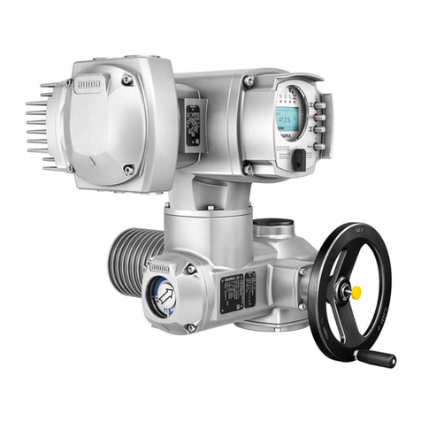
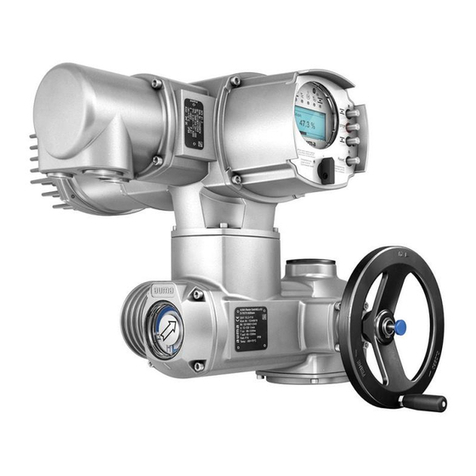
AUMA SEVEN 2SA7 Instruction manual

Issue 08.16 Y070.304/EN
Subject to changes without notice!
Technical Data
Electric Rotary Actuators 2SA7
ECOTRON
PROFITRON
Contents Page
General data Mounting position, duty classifications, noise level, paint finish and
corrosion protection, lubrication, degree of protection, vibration
performance, ambient temperature, installation altitude
2 - 3
Mechanical data ON-OFF duty (2SA70) and
inching/positioning duty(2SA73)
Tripping torque, manual force, flange
size, output shaft design,
output speed, position recording,
revs/stroke
4 - 5
Modulating duty (2SA75) Actuating torque, tripping torque,
manual force, flange size,
output shaft design, output speed,
position recording, revs/stroke
6 - 7
Flange and output shaft dimensions 8
Dimensional drawings 9 - 13
Electrical data Power supply - ON-OFF duty (2SA70) and
inching/positioning duty (2SA73)
14 - 15
- Modulating duty (2SA75) 16
Control and feedback signals 17 - 19
Wiring diagrams 20 - 27

Electric Rotary Actuators 2SA7
Technical Data
Page 2 Y070.304/EN
General data
SIPOS actuators are suitable for automatic and safe operation of industrial valves in accordance with EN 15714-2.
Mounting position
The actuator can be mounted in any position. To make local operation easier, e.g. reading information on the display, a regular mounting is
recommended, i.e. the mounting flange of the valve should be positioned below the actuator.
The electronics unit of the actuator can be mounted separately (e.g. wall bracket) using our separate mounting kit (e.g. order add-on S41).
Duty classifications
2SA70..-
oON-OFF duty, class Aaccording to EN 15714-2
oShort-time duty S2-15 min according to DIN EN 60034
2SA73..-
oInching/positioning duty, class Baccording to EN 15714-2
2SA75..-
oModulating duty, class C according to EN 15714-2
oIntermittent duty S4/S5 min. 25 % ED duty cycle, 1200 c/h according to DIN EN 60034
In S4 duty (without electr. braking) and S5 duty (with electr. braking) with at least 25 % relative on-time, 1,200 cycles per hour are ensured.
The actuators can be operated for all torque and speed combinations for the entire temperature range from -20 °C to +60 °C.
Noise level
The noise level caused by the actuator (sound pressure level at 1 m distance) is < 70 dB (A).
Paint finish and corrosion protection
All outside screws are exclusively made of stainless steel. The housing material consists of a corrosion-resistant aluminum alloy for normal
atmospheric ambient conditions. Rotary actuators 2SA7 can be used without coating but are painted with a 2K-PUR-single layer coat (two-
component polyurethane single layer coating) as standard.
The single layer coating is UV-resistant and decontaminable. It is applied with a minimum coating thickness of 80 m when dry, in color similar to
RAL 7037 (silver-gray). Other RAL colors (add Y35 + number of RAL color to order) are available.
After roughening and cleaning the surfaces, the single layer coating can be painted with all common painting material. This includes epoxid
lacquers, nitrocellulose lacquers etc.
Protection against corrosion from outside is stipulated in corrosivity categories in accordance with EN15714-2 (EN ISO 12944-2):
Version Standard version:
Corrosivity category C5
Very high corrosion protection,
corrosivity category C5
with long protection time
Installation /
Environmental condition
- Industrial areas with high humidity and
aggressive atmosphere
- Areas with almost permanent condensation and with
high pollution
- Coastal and offshore areas with high salinity
- Industrial areas with high humidity and
aggressive atmosphere
- Areas with almost permanent condensation and with
high pollution
Order add-on --- L38

Electric Rotary Actuators 2SA7
Technical Data
Y070.304/EN Page 3
Lubrication
The gears are filled with durable gear oil. They therefore require little maintenance. The maintenance intervals after commissioning must be ob-
served (refer to recommendations in operating manual). The bearings of output shaft type A are lubricated with grease.
Degree of protection
The actuators meet the requirements of IP68 protection as standard (DIN EN 60529).
They are fully screen-protected (electrical voltage and moving parts) and protected against the ingress of foreign bodies (dust), and against harm-
ful quantities of water on continuous immersion up to max. 3 m head of water for a duration of max. 72 hours. During flooding up to 10 motor
operations (switching cycles) are permitted.
IP68-8, continuous immersion up to max. 8 m head of water, on request!
Vibration performance
Electric rotary actuators 2SA7 are certified according to:
Acceleration Frequency range Throughput speed Test duration
Germanischer Lloyd 0.7 g 5 – 200 Hz in the resonance frequencies min. 1.5 h / in 3 directions
EN 60068-2-6 2 g 5 – 500 Hz 1 octave/min 20 sweeps (10 cycles) / in 3 directions
Loads according to EN 60068-2-6 up to 5 g for separate mounting of electronics and gear unit on request.
The actuators can withstand a continuous load caused by plant-generated vibrations within a frequency range of 5 Hz – 200 Hz at up to 0.5 g.
Ambient temperature
There are no functional restrictions for the temperature range of -20 °C to +60 °C. Lower or higher temperatures on request!
Installation altitude above sea level
The actuators are designed for an installation altitude up to 2,000 m above sea level.
Since the insulating properties of air decrease with increasing installation altitude, a voltage derating for the maximum permissible operating volt-
age has to be considered at installation altitudes above 2,000 m.
Installation altitude
above sea level [m]
Derating
factor
permissible
operating voltage
[V AC]
2000 1 460 + 15% (530 + 0%)
3000 0.88 405 + 15% (465 + 0%)
4000 0.77 355 + 15% (410 + 0%)
When considering a limited permissible voltage tolerance, SIPOS actuators can be safely operated at installation altitudes of up to 4,000 m with 3-
phase 400 V AC (–15%/+0%).
530
460
400
[V AC]
380
permissible operating voltage
Voltage derating
(Rated operating voltage 530 V AC = 460 V AC +15%)
Installation altitude above sea level
[m]
2000 3000 4000

Electric Rotary Actuators 2SA7
Technical Data
Page 4 Y070.304/EN
Mechanical data 1 2 3 4 5 6 7 - 8 9 10 11 12 13 14 15 16
ON-OFF dut
y
2SA70 - -
Inchin
g
/
p
ositionin
g
dut
y
2SA73 - -
Tripping torque
Adjustable tripping torque TC[Nm]
typical running torque > 50% max. torque TCmax. 1)
Force for manual mode 2)
>> self-locking version (i = 40) <<
Weight
≈[kg] Crank length /
hand wheel dia.
at TCmax.
9 – 30 19 1 60 mm 31 N
18 – 60 20
2 63 N
37
–
125 3) 34
3 90 mm 87 N
75 – 250 38
4 174 N
150 – 500 69
5
Ø 250 mm
125 N
300 – 1000 69
6 250 N
600 – 2000 136
7 132 N
1200 – 4000 136 8 263 N
Adjustable tripping torque in steps of 10% from 30%-100% max. torque TCmax.
Tripping torque
range [Nm]
Tripping torque setting at .. % of TCmax. [Nm]
30 % 40 % 50 % 60 % 70 % 80 % 90 % 100 %
9 - 30 9 12 15 18 21 24 27 30
18 - 60 18 24 30 36 42 48 54 60
37
-
125
3) 37 50 62 75 87 100 112 125
75 - 250 75 100 125 150 175 200 225 250
150 - 500 150 200 250 300 350 400 450 500
300 - 1000 300 400 500 600 700 800 900 1000
600 - 2000 600 800 1000 1200 1400 1600 1800 2000
1200 - 4000 1200 1600 2000 2400 2800 3200 3600 4000
permitted tolerance: ± 10% of TCmax.
Flange size
Flange size
for tripping torque [Nm]
Spindle
opening
[mm]
DIN ISO
5210
DIN
3210
F07 - 9-30
Dimensions for
A shaft (d6),
B1 shaft (d5)
and
C shaft (d11)
see page 8
0
F10 G0 9-30 18-60
3
7-125 1
F12 - 37-125 75-250 2
F14 G1/2 37-125 75-250 150-500 3
F16 G3 150-500 300-1000 4
F25 G4 600-2000 5
F30 G5 1200-4000 6
Output shaft design
Output shaft
form DIN 4)
A ISO 5210 Output shaft with threaded bush 0
103 5) + acme screwthread Order-no. with „ - Z “ + Y18
B1 ISO 5210 bore with keyway 2
C 3338 claw coupling 3
B3 ISO 5210 bore with keyway 5
B2 / B4 6) ISO 5210 bore with keyway Order-no. with H2Y
9
1) Exception: 35% for adjustment/setting to highest output speed for the types 2SA701 -.E, 2SA702.-.E, 2SA706.-.C, 2SA706.-.D, 2SA708.-.A and 2SA708.-.B resp.
2SA731 -.E, 2SA732.-.E, 2SA736.-.C, 2SA736.-.D, 2SA738.-.A and 2SA738.-.B and
25 % for 2SA706.-.D, 2SA736.-.D, 2SA708.-.B and 2SA738.-.B for separate mounting >10 m.
2) Non-self-locking actuators (refer to "Output speed“ column) have manual forces 30% higher.
3) Tripping torque range reduced to 37 – 112 Nm for 110 – 115 V connection voltage.
4) Special output shaft and output shaft design acc. to DIN 3210 on request.
5) Acme screw thread LH according to DIN 103, Part 2, thread nominal diameter as listed in Line 1, pitch according to preferred series.
The acme screw thread must be expressly stated, e.g. Tr 16 x 4 LH DIN 103!
6) The special bore must be stated, e.g. ø 26 with featherkey A8x7 DIN 6885!
30 % TCmax. is
default setting
Manual mode
>> Switchover only when drive is at standstill! <<
Switchover takes place by pressing in the hand
crank/hand wheel, motor stops operating automati-
cally.
Electrical operation restarts automatically after
releasing hand crank/hand wheel.
Direction of rotation: Turning hand crank/ hand
wheel clockwise results in clockwise rotation of
output shaft
(Exception: 2SA707.- and 2SA708.- resp.
2SA737.- and 2SA738.-).
Self-locking: The hand crank/hand wheel acts
directly on the motor shaft when turned by hand;
the self-locking function is thus retained for self-
locking actuators.
Dimensions to
flanges and output
shafts, see page 8

Electric Rotary Actuators 2SA7
Technical Data
Y070.304/EN Page 5
1 2 3 4 5 6 7 - 8 9 10 11 12 13 14 15 16
2SA70 - -
2SA73 - -
Output speed
Output speed [rpm]
for tripping torque [Nm]
Speed range default
setting
1.25 - 10 1200-4000 3.5 A
2.5 - 20
600-2000 1200-4000 7 B
5 - 20 1) 9-30 18-60 37-112
5 - 28
600-2000
5 - 40 9-30 18-60 37-125 75-250 150-500 300-1000 14 C
10 - 40 1) 9-30 18-60
10 - 80 9-30 18-60 37-125 75-250 150-500 300-1000 28 D
20 - 56 1) 9-30
20 - 80 1) 18-60
20 - 112 9-30 150-500
20 - 160 18-60 37-125 75-250 56 E
7-stage selectable speeds within selected speed range; step factor 1.4
Speed range
Output speed set to stage... [rpm]
1 2 3 4 5 6 7
1.25 - 10 1.25 1.75 2.5 3.5 5 7 10
2.5 - 20 2.5 3.5 5 7 10 14 20
5 - 20
1)
5 7 10 14 20
--- ---
5 - 28 28 ---
5 - 40 40
10 - 40
1) 10 14 20 28 40 --- ---
10 - 80 56 80
20 - 56
1)
20 28 40 56
--- --- ---
20 - 80
1)
80
--- ---
20 - 112 112 ---
20 - 160 160
Position recording
mechanical
position
indicator
Position recording
without signaling gear with precision metal film potentiometer
0
with 1
without
non-intrusive position encoder – commissioning without opening the actuator
with contactless position detection (without battery), data stored in non-volatile memory,
position indication via progress bar and
additional value indication [%] (only PROFITRON) on the display 2
Setting for signaling gear
Revolutions per stroke (revs/stroke)
setting for
signaling gear
2SA701/2/3/4/5/6 0.8 2.1 5.5 14 36 93 240 610 1575 4020
2SA731/2/3/4/5/6
2SA707/8 0.2 0.52 1.37 3.5 9 23.2 60 152 393 1005
2SA737/8
1) reduced speed range for 110 – 115 V connection voltage
Speed stage 4
is default
setting
Speed setting
Speed is set via the hermetically
sealed control button "DriveController“
of the local control, via fieldbus or the
PC programming software "COM SIPOS“.
In PROFITRON version, different speeds
can be set for OPEN, CLOSE,
EMERGENCY OPEN and EMERGENCY
CLOSE.
36 resp. 9
revs/stroke is
default setting
Adjusting the revs/stroke
Remove the cover from the signaling gear,
adjust the slide wheel so that the gear rim
faces the required value on the scale.
The adjusted value is the value for the
valve, e.g. a stage of 93 must be adjusted for
a valve with 40 revs/stroke.
not self-locking
„non-intrusive“
The non-intrusive version has no signaling
gear.
The exact number of rotations for the travel
(max. 353.000 rev/stroke) are automatically
determined and saved when approaching
both end positions during end position
adjustment.
Self-locking
Self-locking actuators
have a ratio of i=40.
Non-self-locking actuators
have a ratio of i=20.

Electric Rotary Actuators 2SA7
Technical Data
Page 6 Y070.304/EN
Mechanical data 1 2 3 4 5 6 7 - 8 9 10 11 12 13 14 15 16
Modulatin
g
dut
y
2SA75 - -
Tripping torque
Max.
act. torque
(modulating torque)
Adjustable tripping torque TC[Nm] Force for manual mode
Weight
≈[kg]
Crank length /
hand wheel dia.
at TCmax.
15 10 – 20 19
1 60 mm 21 N
30 20 – 40 20
2 42 N
60 40 – 80 34
3 90 mm 56 N
125 87 – 175 38
4 122N
250 175 – 350 69
5
Ø 250 mm
88 N
500 350 - 700 69
6 175 N
1000 700– 1400 136
7 92 N
2000 1400-2800 136
8 184 N
Adjustable tripping torque in steps of 10% from 50%-100% max. torque TCmax.
Tripping torque
range [Nm]
Tripping torque setting at .. % of TCmax. [Nm]
50 % 60 % 70 % 80 % 90 % 100 %
10 - 20 10 12 14 16 18 20
20 - 40 20 24 28 32 36 40
40 - 80 40 48 56 64 72 80
87 - 175 87 105 122 140 157 175
175 - 350 175 210 245 280 315 350
350 - 700 350 420 490 560 630 700
700 - 1400 700 840 980 1120 1260 1400
1400 - 2800 1400 1680 1960 2240 2520 2800
permitted tolerance: ± 10% of TCmax.
Flange size
Flange size
for tripping torque [Nm]
Spindle
opening
[mm]
DIN ISO
5210
DIN
3210
F07 - 10-20
Dimensions for
A-shaft (d6),
B1-shaft (d5)
and
C-shaft (d11)
see page 8
0
F10 G0 10-20 20-40 40-80
1
F12 - 40-80
87-175 2
F14 G1/2 40-80 87-175 175-350 3
F16 G3
175-350 350-700 4
F25 G4
700-1400 5
F30 G5 1400-2800
6
Output shaft design
Output shaft
form DIN 1)
A ISO 5210 Output shaft with threaded bush 0
103 2) + acme screw thread Order-no. with „ - Z “ + Y18
B1 ISO 5210 bore with keyway 2
C 3338 claw coupling 3
B3 ISO 5210 bore with keyway 5
B2 / B4 3) ISO 5210 bore with keyway Order-no. with H2Y
9
1) Special output shaft and output shaft design acc. to DIN 3210 on request.
2) Acme screw thread LH according to DIN 103, Part 2, thread nominal diameter as listed in Line 1, pitch according to preferred series.
The acme screw thread must be expressly stated, e.g. Tr 16 x 4 LH DIN 103!
3) The special bore must be stated, e.g. ø 26 with featherkey A8x7 DIN 6885!
50 % TCmax. is
default setting
Self-locking
Rotary actuators for modulating duty are
self-locking actuators.
The gear ratio is i=40.
Dimensions to
flanges and output
shafts, see page 8
Manual mode
>> Switchover only when drive is at standstill! <<
Switchover takes place by pressing in the hand
crank/hand wheel, motor stops operating automati-
cally.
Electrical operation restarts automatically after
releasing hand crank/hand wheel.
Direction of rotation: Turning hand crank / hand
wheel clockwise results in clockwise rotation of
output shaft
(Exception: 2SA757.- and 2SA758.-).
Self-locking: The hand wheel acts directly on the
motor shaft when turned by hand; the self-locking
function is thus retained for self-locking actuators.

Electric Rotary Actuators 2SA7
Technical Data
Y070.304/EN Page 7
1 2 3 4 5 6 7 - 8 9 10 11 12 13 14 15 16
2SA75 - -
Output speed
Output speed [rpm]
for tripping torque [Nm]
Speed range default
setting
1.25 - 10 700-1400 1400-2800 3.5 A
5 - 20 1) 10-20 20-40 40-80 14
5 - 40 10-20 20-40 40-80 87-175 175-350 350-700 C
10 - 80 10-20 20-40 40-80 87-175 175-350 28 D
7-stage selectable speeds within selected speed range; step factor 1.4
Speed range
Output speed set to stage... [rpm]
1 2 3 4 5 6 7
1.25 - 10 1.25 1.75 2.5 3.5 5 7 10
5 - 20
1) 5 7 10 14 20 --- ---
5 - 40 28 40
10 - 80 10 14 20 28 40 56 80
Position recording
mechanical
position
indicato
r
Position recording
without signaling gear with precision metal film potentiometer
0
with 1
without
non-intrusive position encoder – commissioning without opening the actuator
with contactless position detection (without battery), data stored in non-volatile memory,
position indication via progress bar and
additional value indication [%] (only PROFITRON) on the display 2
Setting for signaling gear
Revolutions per stroke (revs/stroke)
setting for
signaling gear
2SA751/2/3/4/5/6 0.8 2.1 5.5 14 36 93 240 610 1575 4020
2SA757/8 0.2 0.52 1.37 3.5 9 23.2 60 152 393 1005
1) reduced speed range for 110 – 115 V connection voltage
Speed stage 4
is default
setting
36 resp. 9
revs/stroke is
default setting
Speed setting
Speed is set via the hermetically
sealed control button "DriveController“
of the local control, via fieldbus or the
PC programming software "COM SIPOS“.
In PROFITRON version, different speeds
can be set for OPEN, CLOSE,
EMERGENCY OPEN and EMERGENCY
CLOSE.
„non-intrusive“
The non-intrusive version has no signaling
gear.
The exact number of rotations for the travel
(max. 353.000 rev/stroke) are automatically
determined and saved when approaching
both end positions during end position
adjustment.
Adjusting the revs/stroke
Remove the cover from the signaling gear,
adjust the slide wheel so that the gear rim
faces the required value on the scale.
The adjusted value is the value for the
valve, e.g. a stage of 93 must be adjusted for
a valve with 40 revs/stroke.

Electric Rotary Actuators 2SA7
Technical Data
Page 8 Y070.304/EN
Flange sizes
Rotary actuator
type
2SA7 . 10 11
21 31 32
42 33
43 53 54
64 75 86
Flange size DIN ISO 5210 F07 F10 F10 F12 F14 F16 F25
F30
as per DIN 3210
0 0 1/2 3
4 5
d1 90 125
125 8) 1508) 175 210 210 300 350
d2 55 70 60 70 60 85 100 130 200 160 230 180
d3 70 102 102 125 140 165 254 298 300
d4 M8 M10 M10 M12 M16 M20 M16 M20
z
1)
4 4 4 4 4 4 8 8
h 3 3 3 3 4 5 5 5
h3 12 17 17 20 25 32 24 30
Output shaft dimensions
Hollow shaft with threaded bush form A as per DIN ISO 5210 and
form A as per DIN 3210
d6 max. 2) 26 32 48 48
52 4) 65 75 77 80 5)
d5 32 34 55 55 55 80 80 80 92
h 38 48 86 86 62 108 77 126 155
l 37 47 85 85 61 108 76 126 155
l2 175 173 267 267 243 347 316 691 782
Thrust max. [kN] 7) 40 60 100 120 120 160 160 350 450
Bore with keyway d7 28 42 42 50 60 80 100 120
d5
3)
28 34 42 50 55 60 80 80 80
b1 8 12 12 14 18 22 28 32
t1 31.3 45.3 45.3 53.8 64.4 85.4 106.4 127.4
l1 36 45 45 60 65 70 87 139 139
h1 0 0 0 0 0 0 2 2
l2 150 123 210 210 178 280 236 583 583
Bore with keyway d10 16 20 20 25 30 40 50 60
d
y
max. 28 30 42 50 45 60 60 80 95
d
y
max.
6)
50
60
70 100
b4 5 6 6 8 8 12 14 18
t3 18.3 22.8 22.8 28.3 33.3 43.3 53.8 64.4
l1 36.5 45 52 60 65 70 80 139 139
h1 0 0 0 0 0 0 2 2
Hollow shaft with claw coupling d12 42 42
60 80 100 120
d11
28 28
38 47 64 75
b1
14 14
20 24 30 40
h1
0 0
0 0 2 2
h11
9 9
10 12 11 13
l2
123 210
178 280 236 583 583
Free shaft end with featherkey form D as per DIN 3210 d8 20 20
30 40 50 60
l4
50 50
70 90 110 120
l5
55 55
76 97 117 127
b3
6 6
8 12 14 18
t2
22.5 22.5
33.0 43.0 53.5 64.0
1) number of tapped holes d4 2) max. diameter for the spindle 3) max. diameter for the spindle, if spindle protection tube is necessary; see dimension d6max. (form A) 4) for version
with spindle protection tube max. 50 mm 5) max. ø77 for spindle stroke ≥541 mm for form A resp. ≥348 mm for form B1 (dimensions from connection flange) 6) with adaptation flange
(height on request) 7) only applies to ON-OFF duty and inching/positioning duty, for modulating duty on request 8) 175 mm with output shaft form A
form B3 as per DIN ISO 5210 and
form E as per DIN 3210;
form B2/B4 (dy max.)
form C as per DIN 3338 and
form C as per DIN 3210
form B1 as per DIN ISO 5210 and
form B as per DIN 3210
l1
d5
h1
l2
d7
H9
t1
+0,2
b1
JS9

Electric Rotary Actuators 2SA7
Technical Data
Y070.304/EN Page 9
Dimensional drawing 2SA701., 2SA702., 2SA731., 2SA732., R866851
2SA751., 2SA752.
1 Motor 4 Signaling gear 7 Field bus connection
2 Gear unit 5 Local control station 8 Plug connection
3 Electronics unit 6 Hand crank 9 USB interface (only PROFITRON)
10 Spindle protection tube (for length, see catalog)

Electric Rotary Actuators 2SA7
Technical Data
Page 10 Y070.304/EN
Dimensional drawing 2SA703., 2SA704.-.C, 2SA733., 2SA734.-.C, R866852
2SA753., 2SA754.-.C
1 Motor 4 Signaling gear 7 Field bus connection
2 Gear unit 5 Local control station 8 Plug connection
3 Electronics unit 6 Hand crank 9 USB interface (only PROFITRON)
10 Spindle protection tube (for length, see catalog)

Electric Rotary Actuators 2SA7
Technical Data
Y070.304/EN Page 11
Dimensional drawing 2SA704.-.D, 2SA704.-.E, 2SA734.-.D, 2SA734.-.E, R866853
2SA754.-.D
1 Motor 4 Signaling gear 7 Field bus connection
2 Gear unit 5 Local control station 8 Plug connection
3 Electronics unit 6 Hand crank 9 USB interface (only PROFITRON)
10 Spindle protection tube (for length, see catalog)

Electric Rotary Actuators 2SA7
Technical Data
Page 12 Y070.304/EN
Dimensional drawing 2SA705., 2SA706., 2SA735., 2SA736., R866854
2SA755., 2SA756.
1 Motor 4 Signaling gear 7 Field bus connection
2 Gear unit 5 Local control station 8 Plug connection
3 Electronics unit 6 Hand wheel 9 USB interface (only PROFITRON)
10 Spindle protection tube (for length, see catalog)

Electric Rotary Actuators 2SA7
Technical Data
Y070.304/EN Page 13
Dimensional drawing 2SA707., 2SA708., 2SA737., 2SA738., R866855
2SA757., 2SA758.
2SA7.7. 2SA7.8.
F25 G4 F30 G5
ø D1 200 f8 160
f8 230
f8 180
f8
ø D2 254 298 300
ø D3 300 350
D4 8 x M16 8 x M20
ø D5 50 60
B 110 120
C 117 127
F 130 199
1 Motor 5 Local control station 9 USB interface (only PROFITRON)
2 Gear unit 6 Hand wheel 10 Spindle protection tube (for length, see catalog)
3 Electronics unit 7 Field bus connection 11 Intermediate gear (supplied separately)
4 Signaling gear 8 Plug connection

Electric Rotary Actuators 2SA7
Technical Data
Page 14 Y070.304/EN
Electrical data – Power supply of ON-OFF duty (2SA70) and
Inching/positioning duty (2SA73)
Connection voltage UN 1-phase, 110 – 115 V AC (40 – 70 Hz)
permissible voltage tolerance: -10% / +15%
Type Current (110 V)
2)
3)
Power PN
4)
Motor Fuse
2SA70.., n
max. T
Cmax. Nominal current IN
4)
≈Imax.
5)
power slow blowing
2SA73.. [rpm] [Nm] [A] [A] [kW] [kW] [A]
.....1. -.CB 20
30
2.9 3.1 0.2
0.75 10
-.DB 40 3.1 3.8 0.2
-.EB 56 4.6 5.6 0.3
.....2. -.CB 20
60
3.3 4.2 0.2
-.DB 40 4.8 6.5 0.3
-.EB 80 7.1 9.6 0.4
.....3. -.CB 20 112 6.1 7.9 0.4
Connection voltage UN 1-phase, 220 – 230 V AC (40 – 70 Hz)
permissible voltage tolerance: -10% (-30% 1)) / +15%
Type Current (230 V)
2)
3)
Power PN
4)
Motor Fuse
2SA70.., n
max. T
Cmax. Nominal current IN
4)
≈Imax.
5)
power slow blowing
2SA73.. [rpm] [Nm] [A] [A] [kW] [kW] [A]
.....1. -.CD 40
30
1.7 2.1 0.2
0.75 10
-.DD 80 2.9 3.9 0.4
-.ED 112 2.7 3.6 0.4
.....2. -.CD 40
60
2.3 3.1 0.3
-.DD 80 4.1 5.4 0.5
-.ED 160 6.0 10.0 0.7
.....3. -.CD 40 125 4.5 6.3 0.6
Connection voltage UN 3-phase, 190 – 200 V AC (40 – 70 Hz)
permissible voltage tolerance: -10% (-30% 1)) / +15%
Type Current (200 V)
2)
3)
Power PN
4)
Motor Fuse
2SA70.., n
max. T
Cmax. Nominal current IN
4)
≈Imax.
5)
power slow blowing
2SA73.. [rpm] [Nm] [A] [A] [kW] [kW] [A]
.....1. -.CJ 40
30
1.2 1.5 0.2
0.75 6
-.DJ 80 2.1 2.8 0.4
-.EJ 112 2.0 2.6 0.4
.....2. -.CJ 40
60
1.7 2.3 0.3
-.DJ 80 3.0 3.9 0.5
-.EJ 160 4.4 7.3 0.7
.....3. -.CJ 40 125 3.3 4.6 0.6
Connection voltage UN 3-phase, 380 – 460 V AC (40 – 70 Hz)
permissible voltage tolerance: -10% (-30% 1)) / +15%
Type Current (400 V)
2)
3)
Power PN
4)
Motor Fuse
2SA70.., n
max. T
Cmax. Nominal current IN
4)
≈Imax.
5)
power slow blowing
2SA73.. [rpm] [Nm] [A] [A] [kW] [kW] [A]
.....1. -.CE 40
30
0.6 0.7 0.2
0.75
6
-.DE 80 1.0 1.2 0.4
-.EE 112 1.0 1.2 0.4
.....2. -.CE 40
60
1.2 1.8 0.3
-.DE 80 1.4 1.8 0.5
-.EE 160 1.9 2.6 0.7
.....3. -.CE 40
125
1.4 1.8 0.6
-.DE 80 2.4 3.1 1.0
1.50
-.EE 160 3.4 4.8 1.6
.....4. -.CE 40
250
1.9 2.9 0.9
-.DE 80 4.1 5.4 1.8 3.00 10
-.EE 160 5.9 8.2 2.8 5.50 16
.....5. -.CE 40
500
3.7 5.0 1.7 3.00 10
-.DE 80 7.5 10.0 3.7
5.50 16
-.EE 112 7.7 11.7 3.8
.....6. -.CE 40 1000 5.6 10.8 2.6
-.DE 80 9.4 12.8 4.7
.....7. -.BE 20 2000 7.5 10.0 3.7
-.CE 28 7.7 11.7 3.8
.....8. -.AE 10 4000 5.6 10.8 2.6
-.BE 20 9.4 12.8 4.7
1) full torque for voltage fluctuations between –30 % and +15 %
(in case of undervoltage from UN–30% to –10%, operation may be performed at reduced output speed n)
2) lower voltage increases the current, higher voltage reduces the current
3) starting current IA≤nominal current IN
4) at 35% of the maximum torque TCmax.
5) maximum current Imax. is present for torque-dependent cut-off mode and for a running torque of 50% the maximum torque TCmax.
small
electronics-
unit
small
electronics-
unit
small
electronics-
unit
big
electronics-
unit
small
electronics-
unit

Electric Rotary Actuators 2SA7
Technical Data
Y070.304/EN Page 15
Motor operation
The frequency converter generates a frequency/amplitude adjustable 3-phase AC voltage for the motor from the single or 3-phase main voltage supply. Motor speed
and thus actuator output speed are internally adjusted via the frequency.
Motor protection
The motor has a thermistor-type motor protection against thermal damage. The winding temperature is monitored continuously by the microcontroller. The response
after exceeding the permitted winding temperature is programmable on the PROFITRON. On the ECOTRON the motor protection cannot be inhibited.
Motor space heater (programmable for PROFITRON, for ECOTRON only with option „M18“)
The microcontroller continuously monitors the current winding temperature by means of a temperature sensor integrated in the motor winding. When the motor space
heater is activated by the program, the motor winding is heated by a DC voltage via the frequency converter depending on the cooling characteristic of the motor
winding when the motor is switched off.

Electric Rotary Actuators 2SA7
Technical Data
Page 16 Y070.304/EN
Electrical data – Power supply of Modulating duty (2SA75)
Connection voltage UN 1-phase, 110 – 115 V AC (40 – 70 Hz)
permissible voltage tolerance: -10% / +15%
Current (110 V)
2)
3)
Power PN
4)
Motor Fuse
Type n
max. T
Cmax. Nominal current IN
4)
≈Imax.
5)
power slow blowing
2SA75.. [
rpm] [Nm] [A] [A] [kW] [kW] [A]
.....1. -.CB
20
20 1.9 2.6 0.1
0.75 10.....2. -.CB 40 2.4 3.8 0.2
.....3. -.CB 80 4.2 8.3 0.3
Connection voltage UN 1-phase, 220 – 230 V AC (40 – 70 Hz)
permissible voltage tolerance: -10% (-30% 1)) / +15%
Current (230 V)
2)
3)
Power PN
4)
Motor Fuse
Type n
max. T
Cmax. Nominal current IN
4)
≈Imax.
5)
power slow blowing
2SA75.. [rpm] [Nm] [A] [A] [kW] [kW] [A]
.....1. -.CD 40 20 1.3 1.9 0.2
0.75 10
-.DD 80 2.6 3.8 0.4
.....2. -.CD 40 40 1.7 2.8 0.2
-.DD 80 3.4 5.6 0.4
.....3. -.CD 40 80 3.4 6.2 0.4
Connection voltage UN 3-phase, 190 – 200 V AC (40 – 70 Hz)
permissible voltage tolerance: -10% (-30% 1)) / +15%
Current (200 V)
2)
3)
Power PN
4)
Motor Fuse
Type n
max. T
Cmax. Nominal current IN
4)
≈Imax.
5)
power slow blowing
2SA75.. [
rpm] [Nm] [A] [A] [kW] [kW] [A]
.....1. -.CJ
40
20 0.9 1.4 0.2
0.75 6.....2. -.CJ 40 1.2 2.0 0.2
.....3. -.CJ 80 2.5 4.5 0.4
Connection voltage UN 3-phase, 380 – 460 V AC (40 – 70 Hz)
permissible voltage tolerance: -10% (-30% 1)) / +15%
Current (400 V)
2)
3)
Power PN
4)
Motor Fuse
Type n
max. T
Cmax. Nominal current IN
4)
≈Imax.
5)
power slow blowing
2SA75.. [
rpm] [Nm] [A] [A] [kW] [kW] [A]
.....1. -.CE 40 20 0.5 0.7 0.2
0.75 6
-.DE 80 1.0 1.4 0.4
.....2. -.CE 40 40 0.9 1.7 0.2
-.DE 80 1.8 3.4 0.4
.....3. -.CE 40 80 1.2 1.8 0.5
-.DE 80 2.4 3.6 1.0
1.50
.....4. -.CE 40 175 1.6 3.0 0.7
10
-.DE 80 3.2 6.0 1.4
3.00
.....5. -.CE 40 350 3.0 5.0 1.3
-.DE 80 6.0 10.0 2.6
5.50 16
.....6. -.CE 40 700 5.1 9.5 2.3
.....7. -.AE 10 1400 3.0 5.0 1.3 3.00 10
.....8. -.AE 2800 5.1 9.5 2.3 5.50 16
Motor operation
The frequency converter generates a frequency/amplitude adjustable 3-phase AC voltage for the motor from the single or 3-phase main voltage supply. Motor speed
and thus actuator output speed are internally adjusted via the frequency.
Motor protection
The motor has a thermistor-type motor protection against thermal damage. The winding temperature is monitored continuously by the microcontroller. The response
after exceeding the permitted winding temperature is programmable on the PROFITRON. On the ECOTRON the motor protection cannot be inhibited.
Motor space heater (programmable for PROFITRON, for ECOTRON only with option „M18“)
The microcontroller continuously monitors the current winding temperature by means of a temperature sensor integrated in the motor winding. When the motor space
heater is activated by the program, the motor winding is heated by a DC voltage via the frequency converter depending on the cooling characteristic of the motor
winding when the motor is switched off.
1) full torque for voltage fluctuations between –30 % and +15 %
(in case of undervoltage from UN–30% to –10%, operation may be performed at reduced output speed n)
2) lower voltage increases the current, higher voltage reduces the current
3) starting current IA≤nominal current IN
4) at 35% of the maximum torque TCmax.
5) maximum current Imax. is present for torque-dependent cut-off mode and for a running torque of 70% the maximum torque TCmax.
small
electronics-
unit
kleine
Elektronik-
einheit
small
electronics-
unit
big
electronics-
unit
small
electronics-
unit
small
electronics-
unit

Electric Rotary Actuators 2SA7
Technical Data
Y070.304/EN Page 17
Electrical data – Control and feedback signals
1 2 3 4 5 6 7 - 8 9 10 11 12 13 14 15 16
2SA7 - -
3 ECOTRON: 3 binary inputs 24/48 V DC (OPEN, CLOSE, STOP), 5 binary outputs 24/48 V DC
1 analog output 4 – 20 mA (actual position value), segment display (symbols for parameterization/commissioning)
4 PROFITRON: 5 binary inputs 24/48 V DC (OPEN, CLOSE, STOP, EMERGENCY, Mode), 8 binary outputs 24/48 V DC,
1 analog output 0/4 – 20 mA (actual position value), multicolor graphic display with status indication
A electronics unit without hardware extension
B relay board with 5 outputs for ECOTRON, 8 for PROFITRON
C PROFIBUS DP 1 channel - with V1 and V2 services
D PROFIBUS DP 2 channel - with V1 and V2 services
E MODBUS RTU 1 channel
F MODBUS RTU 2 channel
J HART (only PROFITRON) ECOTRON PROFITRON
K HART + relay board (only PROFITRON) 2SA7. 2SA702SA732SA75
A standard software-function X X X X
B positioner X X
C process controller X
D travel dependent output speed adjustment X X X
E positioner + travel dependent output speed adjustment X X
F external analog output speed setpoint X X X
G positioner + external analog output speed setpoint X X
H positioner with split-range functionality X X
J travel dependent freely adjustable positioning times X X X
K positioner + travel dependent freely adjustable positioning times X X
L process controller + travel dependent freely adjustable positioning times X
4 round plug
Note: All set and parameterized values are stored in non-volatile memories (EEPROM)!
Signal assignment for the binary outputs
- for ECOTRON (also refer to wiring diagrams, signals 1-5):
Signaling set (set 1 to 4 can be adjusted locally in the segment display of the actuator)
Output default setting optional sets with option „Y12“
Set 1 Set 2 Set 3 Set 4
1 Travel end OPEN NO End position OPEN NO End position OPEN NO Travel end OPEN NO
2 Travel end CLOSE NO End position CLOSED NO End position CLOSED NO Travel end CLOSE NO
3 Torque CL/OP reached NC Blinker NO Fault NC Ready+Remote NO
4 Ready+Remote NO Ready+Remote NO Local NO Torque OPEN reached NC
5 Warning motor temp. NC Warning motor temp. NC Warning motor temp. NC Torque CLOSE reached NC
NO = active high, NC = active low
- for PROFITRON (also refer to wiring diagrams, signals 1-8):
Optional free assignment of outputs,
NO/NC optional
(can be changed locally)
Output default setting with option „Y12“ with option „Y15“ with option „Y90“
1 End position OPEN NO Intermediate contact OP NO Intermediate contact OP NO Intermediate contact OP NO End position CLOSED
2 End position CLOSED NO Intermediate contact CL NO Intermediate contact CL NO Intermediate contact CL NO End position OPEN
3 Torque OPEN reached NC Ready+Remote NO Torque OPEN reached NO Torque OPEN reached NO Torque CLOSE reached
4 Torque CLOSE reached NC Torque OPEN reached NC Torque CLOSE reached NO Torque CLOSE reached NO Torque OPEN reached
5 Fault NC Torque CLOSE reached NC Ready+Remote NO Local NC
Torque CL/OP reached
6 Local NO Local NO Local NO
Fault NC
Fault
7 Blinker NO Warning motor temp. NO Blinker NO
Not used Blinker
8 Warning motor temp. NC Fault external voltage NC Warning motor temp. NO Not used Ready
Ready+Remote
NO = active high, NC = active low Local
Intermediate contact CL
Intermediate contact OP
Fault motor temperature
Warning motor temp.
Fault external voltage
Maintenance
Run indication CLOSE
Run indication OPEN
Run indication OPEN/CLOSE
Blinker+ End position CLOSED
Blinker+ End position OPEN

Electric Rotary Actuators 2SA7
Technical Data
Page 18 Y070.304/EN
42
41
40
28
29
30
31
32
33
34
35
1
2
3
4
5
6
7
8
927
26
25
24
23
22
21
20
19
18
17
16
15
14
13
12
11
10
43
44
45
46
47
50
37
38
39
U1 U2
V1
V2
W1
W2
48
49
36
Connections at round plug (plug assignment)
Inputs and outputs ECOTRON PROFITRON
2SA7.2SA702SA73
2SA75
Binary Inputs 2, 3, 4 and 5 2, 3, 4, 5,
9, 10 and 27
Outputs 16 1), 17, 19, 20, 21,
22 and 23
16 1), 17, 19, 20, 21, 22,
23, 24, 25 and 26
Analog Inputs --- 11 and 12 (option) 11 and 12 (option),
13 and 14 (option)
Outputs 7 and 8 7 and 8,
48, 49 and 50 (option)
Relay outputs
(option)
28, 29, 30, 31, 32, 33, 34, 35, 36,
37,40, 41, 42, 43 and 44
28, 29, 30, 31, 32, 33, 34, 35,
36, 37, 40, 41, 42, 43, 44, 45, 46 und 47
Fieldbus
(option)
1 channel 28, 29, 30 and 31 28, 29, 30 and 31
2 channel 28, 29, 30, 31,
32, 33, 34 and 35
28, 29, 30, 31,
32, 33, 34 and 35
Voltage output
„P24 int.“ resp. „P24 gal.“
1, 6,
15 1) and 18 1)
1, 6,
15 1) and 18 1)
Auxiliary 24 VDC supply for
electronics unit „P24 ext.“
38 and 39 38 and 39
Position recording
If the actuator is equipped with a signaling gear, position recording is performed via precision film potentiometer with microcontroller assessment.
The signaling gear reduces the revolutions required for travel to the permissible rotation angle of the precision film potentiometer.
For "non-intrusive – commissioning without opening the actuator" (without signaling gear), the position is recorded with utmost precision and is transmitted to the
microcontroller.
Positioner
Defining an analog position setpoint (0/4–20mA) for the positioner results in precise control of the position corresponding to this value.
The positioner works adaptively. This leads to a continuous automatic adaptation of the threshold value to the controlled system:
hysteresis 0.4% of the travel
response threshold (dead band) adjustable, default setting: 0.2 to 2.5 % of the travel
upward adaptation response threshold is enlarged by 0.1 %, if an OPEN ==> CLOSE ==> OPEN command sequence occurs within 6 seconds
downward adaptation response threshold is reduced by 0.01 %, when no control has taken place within 10.8 seconds
1) Not applicable for version with relay board.
XK
Plug assignment for the
external round plug connection

Electric Rotary Actuators 2SA7
Technical Data
Y070.304/EN Page 19
Power and consumption values
Binary inputs and outputs
binary inputs - Control inputs OPEN, CLOSED, STOP, Emergency and Mode (Emergency and Mode only on PROFITRON)
binary outputs - 8 binary electronic outputs for signals on PROFITRON, 5 outputs on ECOTRON
All binary inputs and outputs are galvanically isolated and potential-free.
Exception: For ECOTRON with relay board, the binary outputs refer to the potential of the electronics.
Binary outputs are resistant to both short-circuits and overloads.
Input Output
24 V DC 48 VDC 24 V DC 48 VDC
Level L - potential (low -) [V DC] 0 - 4 0 - 4 0 – 2.5 0 – 2.5
H - potential (high -) [V DC] 16 - 30 16 – 60 18 - 30 18 – 60
Current (per input or output) [mA] 4 - 7 7 - 15 max. 100 max. 50
Resistance [Ω] 4000 4000 max. 10 max. 10
Analog inputs and outputs
analog inputs - AE1: 0/4-20mA
- AE2: 0/4-20mA (add-on PCB)
analog outputs - AA1: Position actual value (0/4-20mA) active, i.e. with internal power supply 24 V DC
- AA2: Position actual value (0/4-20mA) passive, i.e. with external power supply 24 V DC (add-on PCB)
Analog inputs and outputs are galvanically isolated (only PROFITRON).
AE2 and AA2 are located on a common add-on PCB and have the same potential.
For existing add-on PCB (AE2+AA2), assignment of AE1 and AE2 analog inputs as well as AA1 and AA2 analog outputs is freely programmable.
Analog outputs are resistant to both short-circuits and overloads.
Input Output
Current [mA] 0 - 20 (max. 24) 0 - 20 (max. 21)
Resistance / load [Ω] 45 max. 600
Ranges 0-20mA or 4-20mA with rising or falling level can be adjusted for PROFITRON; for ECOTRON, the curve is rising (4-20mA).
Relay outputs
Relay outputs are galvanically isolated.
DC
for resistive load AC
max. switching capacity 180 W (for 30 V) 1500 VA
max. switching voltage 30 V 50 V 300 V 250 V
max. switching current 6 A 0.6 A 0.15 A 6 A
The PROFITRON relay board has 8 relay outputs (5 NO, 1 NC and 2 change-over contacts), the 5 relay outputs of the ECOTRON are all designed as
change-over contacts.
Internal 24 V power supply
Only for PROFITRON are the binary inputs and outputs galvanically isolated from the electronics in case of internal 24V DC power supply
via „P24 gal.“.
External 24 V power supply
During power failure, both actual position value and device state are still sent via the external 24V DC supply „P24 ext.” to the binary
signal outputs (signals 1-8) and communication via COM-SIPOS or fieldbus is available.
During mains operation, own supply via actuator.
External 24V power supply Current consumption
Input P24 ext. min. 20 V
(21 V with relay board) typ. 24 V
Σcurrent standard version [mA] 155 140
additional load:
with Fieldbus, 1 channel [mA] +20 +20
with Fieldbus, 2 channel [mA] +40 +40
with HART [mA] +18 +21
with relay board [mA] +50 +60
with „non-intrusive“ [mA] +10 +10
with actual position value [mA] +20 +20
with Bluetooth [mA] +10 +10

Electric Rotary Actuators 2SA7
Technical Data
Page 20 Y070.304/EN
Wiring diagram ECOTRON Y070.243
Wire cross-section max.:
The control/feedback wire must be shielded!
Power supply
Control and feedback signals
6 mm2
2.5 mm2
-
-
1) galvanically isolated areas: can be supplied from different sources with 24/48V DC
2) auxiliary 24V DC supply for electronics unit (if required)
(In case of mains failure both actual position value and actuator status (binary outputs 1-5) will continued to be signalled.
Communication via COM-SIPOS – changes of parameters resp. download of actuator data – is possible.)
Plug assignment XK
42
41
40
28
29
30
31
32
33
34
35
1
2
3
4
5
6
7
8
927
26
25
24
23
22
21
20
19
18
17
16
15
14
13
12
11
10
43
44
45
46
47
50
37
38
39
U1 U2
V1
V2
W1
W2
48
49
36
23
Wiring example II: „external 24/48V DC supplies“
(in this example all galvanically isolated areas are supplied externally from different
24/48V DC power sources)
5
U1
+
-
(DC)
43816 17 2321 2219 20
U2
+
-
(DC)(24VDC)
2)
39
+
-
U3
Wiring example I: „internal 24V DC supply“
(here all inputs and outputs are supplied internally from the electronics unit with 24V DC)
Customer connection - wiring examples:
1234 2321 2219 201715 16185 6
Connection control and feedback signals
Inputs
max. 125 mA
2)
1)
Outputs
binary
24/48V
binary
24/48V
+-
24V DC
38 39
P24 ext.
G24 ext.
XK 234 5
1)
CLOSE
OPEN
G-BI
STOP
19 2321 222016 17
Output 5
Output 4
Output 3
Output 2
Output 1
P-BO
G-BO
161815
P24 int.
G24 int.
P24 int.
G24 int.
Customer connection Actuator internal
Connection power supply
L2
L1
XK
L3
PE
XK W1U1 V1
L3L1 L2 PE
380-460V AC /
190-200V AC
3 phase input1 phase input
N
L1
U2 V2
LN
PE
PE
220-230V AC /
110-115V AC
XKXK
Actuator internalCustomer connection
78
+
-
analog
4...20mA
AO1
A
A
78
78
Table of contents
Other AUMA Controllers manuals
AUMA
AUMA SA 16.2 User manual
AUMA
AUMA SA 3 User manual
AUMA
AUMA SA 48.1 SAR 25.1 User manual
AUMA
AUMA SAVEx Series User manual
AUMA
AUMA SAEx 07.2 User manual
AUMA
AUMA GSTI Series User manual
AUMA
AUMA GK 10.2 User manual
AUMA
AUMA SAVEx 07.2 User manual
AUMA
AUMA SA3-SA100 User manual
AUMA
AUMA TIGRON TR-M30X User manual
AUMA
AUMA SAV 07.2 User manual
AUMA
AUMA SG 03.3 Series User manual
AUMA
AUMA NORM SQ 05.2 Administrator Guide
AUMA
AUMA SGM 04.1 User manual
AUMA
AUMA ACE C 01.2 Profinet Series User manual
AUMA
AUMA SA 3 User manual
AUMA
AUMA SA 07.2 User manual
AUMA
AUMA SA 07.1 User manual
AUMA
AUMA SAN 07.2 User manual
AUMA
AUMA SQ 05.2 User manual
