Bartington Mag648 User manual

www.bartington.com
INNOVATION IN MAGNETICS
Bartington Instruments Ltd
5, 8, 10, 11 & 12 Thorney Leys Business Park
Witney, Oxford, OX28 4GE. England
®The copyright of this document is the property of Bartington Instruments Ltd.
Bartington is a registered trademark of Bartington Instruments Limited in the following countries: Australia, Brazil, Canada, China, European Union, India,
Israel, Japan, Mexico, New Zealand, Norway, Russia, Singapore, South Korea, Switzerland, Turkey, United Kingdom, United States of America and Vietnam.
OM2298/4
Operation Manual for
Mag648 and Mag649™
Low Power Three-Axis Magnetic Field Sensors

BARTINGTON INSTRUMENTS
Page 2 of 9 OM2298/4
Table of Contents
1. About this Manual 3
1.1. Symbols Glossary 3
2. Safe Use 3
3. Introduction to the Mag648 & Mag649™ Series 4
4. General Description 4
4.1. Vector Measurements and Conventions 4
5. Connections 5
5.1. Cable Recommendations 5
5.2. Connection to Power Supply/Acquisition Unit 5
5.4. Mounting Recommendations 6
6. Using the Mag648 and Mag649™ 6
6.1. Mag648 and Mag649™ Operation 6
6.2. Electromagnetic Compatibility 7
7. Troubleshooting 7
8. Care and Maintenance 8
8.1. Calibration 8
9. End of Life Disposal 8
BARTINGTON INSTRUMENTS
Page 3 of 9 OM2298/4
1. About this Manual
This manual provides the information necessary to help customers connect, install and operate,
the Mag648 and Mag649™ magnetic field sensors.
Technical specifications of the products, including power supply requirements and analogue
output details, can be found in DS2298, whilst outline drawings of both sensor head, electronics
board and cable can be found on the Mag648/Mag649 product page.
1.1. Symbols Glossary
The following symbols used within this manual call your attention to specific types of
information:
WARNING: Indicates a situation in which serious bodily injury or death could result if the
warning is ignored.
Caution: Indicates a situation in which bodily injury or damage to your instrument, or both,
could result if the caution is ignored.
Indicates a situation in which ESD protection should be used.
Identifies items that must be disposed of safely to prevent unnecessary damage to the
environment.
Note: A paragraph in this format provides useful supporting information on how to make
better use of your purchase.
2. Safe Use
WARNING: These products are not qualified for use in explosive atmospheres or life
support systems. Consult Bartington Instruments for advice.
WARNING: Environmental and electrical specifications should not be exceeded.
To prevent irreparable damage, electrostatic discharge (ESD) protection and precautions
must be used when handling the unpackaged sensor electronics board.
Note: Do not expose to strong magnetic fields while being stored as this can magnetise
the sensor and affect its offset performance.
BARTINGTON INSTRUMENTS
Page 4 of 9 OM2298/4
3. Introduction
Both the Mag648 and Mag649™ are magnetometers consisting of a cluster of three, feedback
stabilised, fluxgate sensors arranged along X, Y and Z axes. Each axis provides a highly
linear magnetic response, with low hysteresis and low crosstalk between axes. These
characteristics, combined with the compact design and very low power consumption, make
these magnetometers ideally suited for perimeter surveillance within a multi-sensor network.
Regulating the power supply internally ensures the Mag64x series is suitable for battery powered
operation, over both long and short cables.
The Mag649™ offers a wider bandwidth than the standard Mag648.
High stability circuitry ensures that a minimum of ten years’ service should be expected.
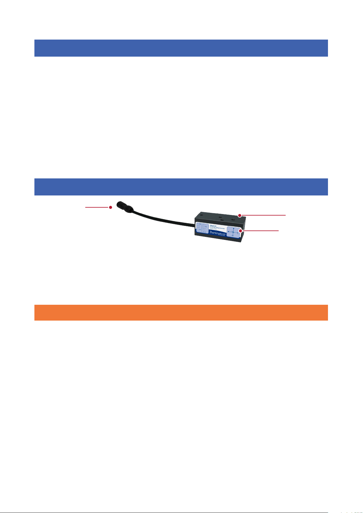
4. General Description
Key:
1. Connector cable 2. Sensing Elements
3. Mounting Holes
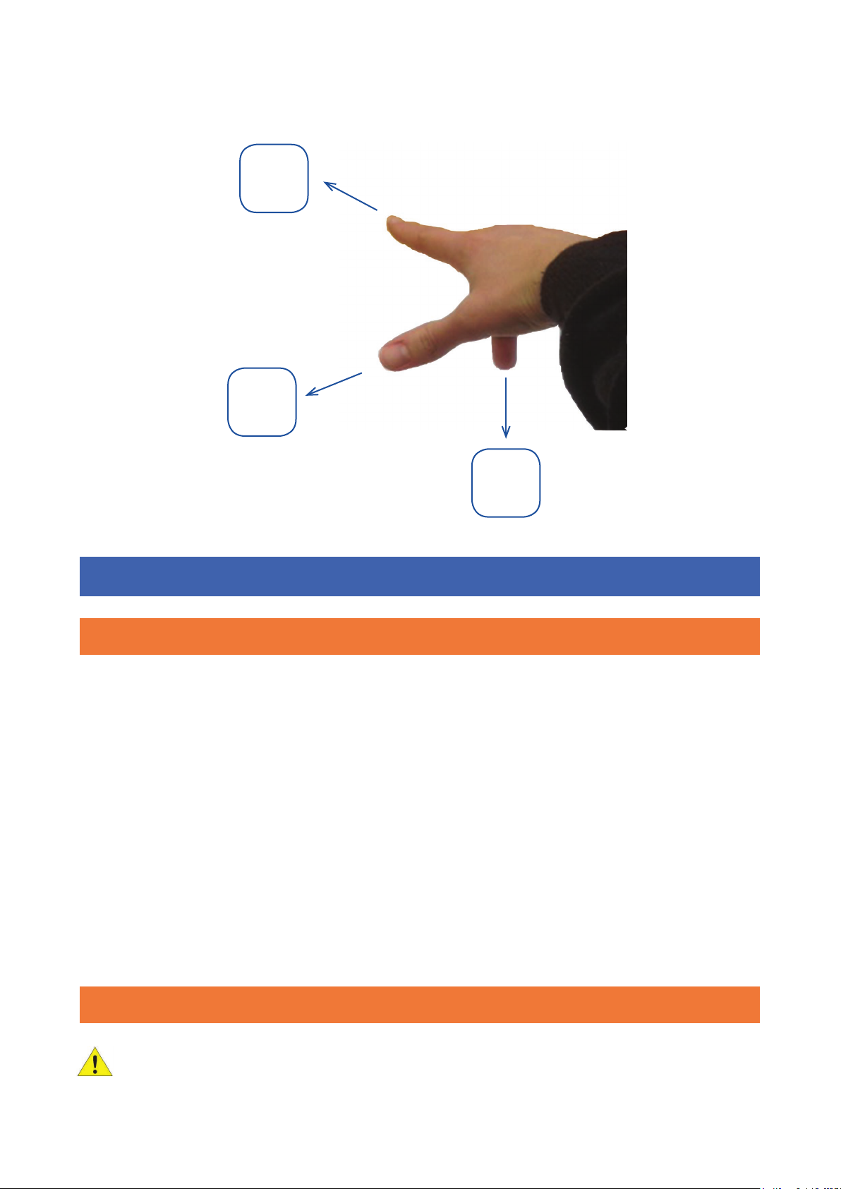
4.1. Vector Measurements and Conventions
Each magnetometer produces three independent analogue output voltages in response to the
magnitude and direction of the orthogonal components of a magnetic field. A “right-hand” co-
ordinate system is adopted (see figure 1). In this system the X, Y and Z axis correspond to the
thumb, first and second finger respectively of the right hand. By convention, the magnetometer
should be installed so that the X axis is arranged to point North, the Y axis to point East and the Z
axis to point down.
The centres of the three vector sensors are superimposed; each orientation is denoted on the
magnetometer’s label. The point of each vector arrow indicates the positive direction of each
axis.
2
3
1
BARTINGTON INSTRUMENTS
Page 5 of 9 OM2298/4
North
+X
Thumb
Down
+Z
2nd Finger
East
+Y
1st Finger
5. Connections
5.1. Cable Recommendations
The Mag648 and Mag649™ electronics board provides balanced output lines for analogue signal
transmission. Suitable shielded cables can be supplied.
Cables are particularly prone to wear and damage if twisted, flexed beyond their design limits, or
subjected to excessive or repeated movement. All cables should be mounted securely in place.
When designing their own cable, the following recommendation should be followed:
• ensure that the cables are shielded to prevent them picking up electromagnetic
interference.
• the cable shield should be connected to power supply ground at the power supply end
(either through the connector body, or by connecting the shield to the power ground
wire).
5.2. Connection to Power Supply/Acquisition Unit
Caution: When providing your own power supply, do not exceed the voltage rating, provide
sufficient current, and ensure correct polarity is respected see DS2298.
Figure 1. The ‘right hand’ rule.
Other manuals for Mag648
1
This manual suits for next models
1
Table of contents
Other Bartington Accessories manuals


