BARTINGTON INSTRUMENTS
Page 4 of 9 OM2497/4
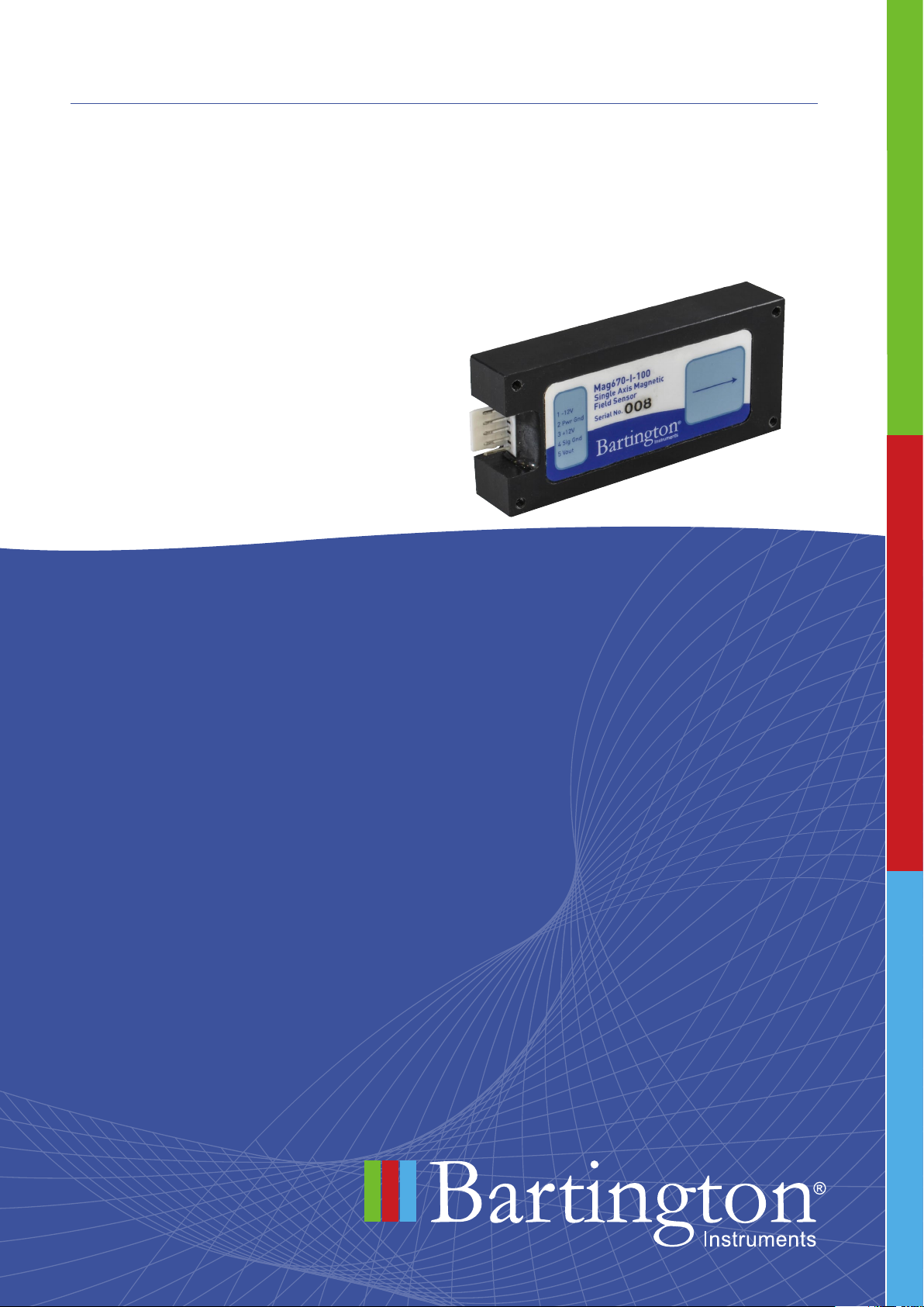
3. Introduction to the Mag670
The Mag670 is a single-axis fluxgate sensor that provides highly linear magnetic response and
low hysteresis. Each instrument consists of a single, feedback-stabilised, fluxgate sensing
element arranged along the length of the enclosure, which is orientated to point away from the
unit’s connector.
The sensor has no power supply or data processing abilities of its own and must always be
connected to a power supply to be able to function.
Regulating the power supply internally ensures that the Mag670 is suitable for battery-powered
operation, over both long and short cables.
Packaged and unpackaged versions are available.
4. Installing the Mag670
4.1. Siting the Sensor (Environment Recommendations)
Note: Site the sensor several metres from any magnetic base rock to avoid compromising
measurements.
Note: Site the sensor several tens of metres from very large ferromagnetic objects that
could create fields exceeding the measuring range of the sensor.
Note: Avoid siting the sensor near any ferromagnetic objects that may be subjected to the
effects of magnetic hysteresis, which would affect the sensor in an unpredictable manner.
Note: Conduct a magnetic evaluation of any proposed installation site to establish that
it is free from magnetic contaminants. Carry out such an evaluation using total field or
resonance sensors.
4.2. Cable Recommendations
Note: The connecting cable to the sensor should be a five-core screened cable. Two cores
will be used for positive and negative power supply lines, one core for output signal, one
core for signal common, and one for power supply ground. The screen should be connected
to supply ground at the supply end only. The capacitance between cores should be less
than 200pF per metre.
Note: Pin out values are shown in drawings DR2545 and DR2945.
Note: Leads are susceptible to electromagnetic interference and should be screened
wherever possible.