Bartington Mag648 User manual

Operation Manual for
Mag648 and Mag649
Low Power Three-Axis Magnetic Field Sensors

BARTINGTON INSTRUMENTS
Page 2 of 11
OM2298/3
Table of Contents
1. About this Manual 3
1.1. Symbols Glossary 3
2. Safe Use 3
3. Introduction to the Mag648 & Mag649 Series 3
3.1. Vector Measurements and Conventions 4
4. Installing the Mag648 or Mag649 5
4.1. Siting the Magnetometer (Environment Recommendations) 5
4.2. Cable Recommendations 5
4.3. Pre-Installation Tests 6
4.4. Mounting Recommendations 7
4.5. Post Installation Testing 7
5. Using the Mag648 and Mag649 8
5.1. Magnetic Hysteresis 8
5.2. Environmental Precautions 8
6. Troubleshooting 8
7. Care and Maintenance 9
7.1. Cleaning Mag648 and Mag649 Magnetometers 9
7.2. Calibration 9
8. End of Life Disposal 10
8.1. Waste Electrical and Electronic Equipment (WEEE) Regulations 10
BARTINGTON INSTRUMENTS
Page 3 of 11
OM2298/3
1. About this Manual
This document describes the installation, operation and maintenance of the Mag648 and Mag649
magnetic field sensors.It should be read in conjunction with product brochure DS2298 and
outline drawings which can be found on the product page on the Bartington Instruments website
at www.bartington.com.
Note that failure to follow the instructions in this manual may invalidate your product’s warranty.
If in doubt, do not hesitate to contact Bartington Instruments.
1.1. Symbols Glossary
The following symbols used within this manual call your attention to specific types of information:
WARNING: Indicates a situation in which serious bodily injury or death could result if the
warning is ignored.
Caution: Indicates a situation in which bodily injury or damage to your instrument, or both,
could result if the caution is ignored.
Identifies items that must be disposed of safely to prevent unnecessary damage to the
environment.
Note: A note provides useful supporting information and sometimes suggests how to make
better use of your purchase.
2. Safe Use
WARNING: These products are not qualified for use in explosive atmospheres or life
support systems. Consult Bartington Instruments for advice.
Caution: To prevent irreparable damage, electrostatic discharge (ESD) protection and
precautions must be used when handling the unpackaged sensor electronics board.
3. Introduction to the Mag648 & Mag649 Series
Both the Mag648 and Mag649 are magnetometers consisting of a cluster of three, feedback
stabilised, fluxgate sensors arranged along X, Y and Z axes. Each axis provides a highly
linear magnetic response, with low hysteresis and low crosstalk between axes. These
characteristics, combined with the compact design and very low power consumption, make
these magnetometers ideally suited for perimeter surveillance with a multi-sensor network.
Regulating the power supply internally ensures the Mag64x series is suitable for battery powered
operation, over both long and short cables.
BARTINGTON INSTRUMENTS
Page 4 of 11
OM2298/3
The Mag649 offers a wider bandwidth than the standard Mag648.
High stability circuitry ensures that a minimum of ten years’ service should be expected.
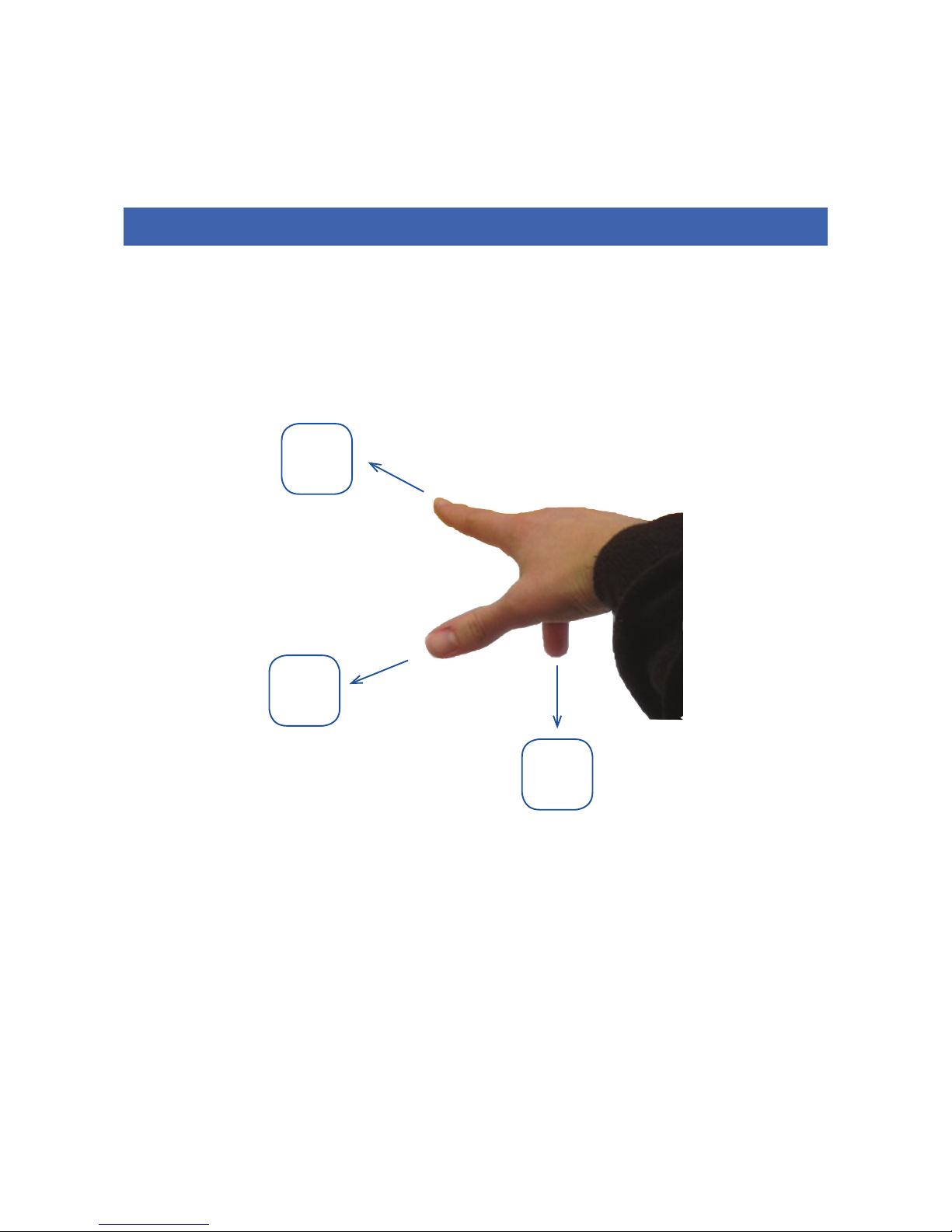
3.1. Vector Measurements and Conventions
Each magnetometer produces three independent analogue output voltages in response to the
magnitude and direction of the orthogonal components of a magnetic field. A “right-hand” co-
ordinate system is adopted (see figure 1). In this system the X, Y and Z axis correspond to the
thumb, first and second finger respectively of the right hand. By convention, the magnetometer
should be installed so that the X axis is arranged to point North, the Y axis to point East and the Z
axis to point down.
Figure 1. The ‘right hand’ rule.
North
+X
Thumb
Down
+Z
2nd Finger
East
+Y
1st Finger

BARTINGTON INSTRUMENTS
Page 5 of 11
OM2298/3
The centres of the three vector sensors are superimposed; each orientation is denoted on the
magnetometer’s label. The point of each vector arrow indicates the positive direction of each
axis.
4. Installing the Mag648 or Mag649
4.1. Siting the Magnetometer (Environment Recommendations)
Note: Site the magnetometer several metres from any magnetic base rock to avoid
compromising measurements.
Note: Site the magnetometer several tens of metres from very large ferromagnetic objects
that could become magnetised and create fields exceeding the measuring range of the
sensor.
Note: Avoid siting the sensor near any ferromagnetic objects that may be subjected to the
effects of magnetic hysteresis, which would affect the sensor in an unpredictable manner.
Note: For these reasons, a magnetic evaluation of any proposed installation site should be
conducted to establish that it is free from magnetic contaminants. It is recommended that
such an evaluation be carried out using total field or resonance magnetometers.
4.2. Cable Recommendations
The standard magnetometer provides differential output lines for analogue signal transmission.
The advantages of this differential arrangement are very high common-mode noise rejection
and the suitability of readily available cable types. Each of the two anti-phase output lines has
low output impedance at the signal source, damping the lines and preventing ringing. Cable
inductance and capacitance considerations require the cable to be terminated with a differential
amplifier having a circa 50kΩ input impedance. This arrangement will provide some damping to
high frequencies but will attenuate the signals above the frequency range of the sensor.
Due to these effects:
• The cable pair loop resistance should not exceed 0.1 ohms per metre.
• The pair loop inductance should not exceed 0.5 micro-Henry per metre.
• The capacitance between should not exceed 52pF per metre.
• The capacitance between conductors and shield should not exceed 120pF per metre.
To optimise operational life of underwater cables and avoid physical damage to the joint during
handling:

BARTINGTON INSTRUMENTS
Page 6 of 11
OM2298/3
1. Use a water-blocked cable.
2. Reduce the risk of stress on the soldering by ensuring there is adequate slack in the wire
between the cable and the wire terminations.
3. Brace the slack with epoxy resin before moulding the cable to the connector.
4. Fit additional protection in the form of a plastic hose, or sleeve, around the cable(s) at the
emergence point.
Note: Cables are particularly prone to wear and damage at the point where they emerge at
the surface of the ground, or sea.
4.3. Pre-Installation Tests
Prior to the installation of the system, the magnetometer, cable and power supply must be fully
tested to ensure correct function as follows:
Caution: Take care to avoid bending, or otherwise damaging the contacts whilst conducting
the tests.
1. Test the cables for continuity (using an electrical continuity tester or ohmmeter).
a. Test the cables end to end at the connectors to ensure the correct pins have been
allocated to the conductors and there are no open, or high resistance circuits.
Note: Cable resistance will vary: refer to the product brochure for the expected values.
b. Test the cables at the connectors to ensure there are no short circuits between the
conductors.
2. Check the power supply output voltage using a voltmeter. Refer to the product brochure
for the required values.
Caution: Ensure the polarity is correct. Incorrect polarity is likely to irreparably damage
the sensor.
Note: Bartington recommends the use of a current-limited power supply.
3. Connect the magnetometer to the cable connector.
4. Connect the power supply to the other cable connector.
5. Switch on the power supply and wait until the magnetometer has stabilised. Refer to the
product brochure for warm-up times.
6. Confirm no magnetic objects are moving in the vicinity.

BARTINGTON INSTRUMENTS
Page 7 of 11
OM2298/3
7. For each of the three (X, Y and Z) axes in turn:
a. Connect a voltmeter to the axis sensor outputs.
b. Whilst monitoring the voltmeter readings, align the magnetometer with the
terrestrial field until the maximum voltage value is determined.
c. Confirm the measured readings approach the local geomagnetic field value.
Note: Geomagnetic field values can be provided by your local magnetic observatory. A
margin of error due to local disturbance should be taken into account.
4.4. Mounting Recommendations
Each magnetometer has a set of mounting holes to allow attachment to a stable base or fixture.
Refer to the mechanical drawings on the product page.
Caution: (For the Mag648S and Mag649S only) Take care to align the cable to the connector
correctly, to avoid damage to the connector or magnetometer. When aligned correctly,
hand tighten the connector. Refer to the product brochure for detailed information.
Note: Other versions of the Mag648 and Mag649 have plug-in type connectors.
The sensor can also mounted on the Bartington Instruments Mag-TA Universal Tripod Adaptor.
See brochure DS3140, available from Bartington Instruments, for instructions on how to do this.
4.5. Post Installation Testing
1. Site the magnetometer, and install the power supply and cabling.
2. Switch on the power supply and wait until the magnetometer has stabilised. Refer to the
product brochure for warm-up times.
3. Confirm no magnetic objects are moving in the vicinity.
4. Monitor the sensor outputs.
5. Confirm that the vector sum of the measured magnetic field vectors is similar to the
expected local earth field.
Note: When in a magnetically stable environment the outputs from the sensor should
remain stable to within the quoted noise limits. Refer to the product brochure for the
expected values.

BARTINGTON INSTRUMENTS
Page 8 of 11
OM2298/3
5. Using the Mag648 and Mag649
5.1. Magnetic Hysteresis
Both the Mag648 and Mag649 are designed to have an extremely low magnetic hysteresis.
However, Bartington Instruments recommends your magnetometer is not subjected to magnetic
fields greater than their stated measuring range for extended periods as this could alter the DC
offset. If this occurs, the offset will exhibit drift as it returns to its original offset specification.
Caution: Subjecting the magnetometer to fields in excess of 2 x the nominal range may
cause inaccuracy in future measurements. Degaussing the magnetometer can reverse
such an effect.
5.2. Environmental Precautions
Refer to the product brochure for maximum environmental electrical and mechanical ratings.
Caution: Exceeding the maximum environmental ratings may cause irreparable damage to
your sensor.
6. Troubleshooting
The sensor is unlikely to suffer any defects in normal use: no internal components are
serviceable. The most likely causes of failure, and their solutions, are detailed in the following
table.
In the event of any apparent malfunction beyond those described in the table below, please email
[email protected]om, or telephone the Bartington Instruments service team on +44 (0)1993
706565.
Causes of failure Solution
Power supply Check the power supply as detailed in Pre-
Installation Tests.
Cables Check the cables as detailed in Pre-
Installation Tests. In some cases damaged
connectors can be replaced. Contact the
Bartington Instruments helpdesk for further
advice.

BARTINGTON INSTRUMENTS
Page 9 of 11
OM2298/3
Power input If no fault can be found in the power
supply or cables, ensure the cable length
is not too long, causing excessive voltage
drop between the power supply and
magnetometer. Refer to the specifications
defined in the product brochure.
Magnetometer (packaged) Physical damage or damage to the
electronics of these types of Mag648 or
Mag649 magnetometers is irreparable.
Replace with a new unit. For information
about disposal of the damaged unit, refer to
End of Life Disposal.
Magnetometer (unpackaged) Physical damage or damage to the
electronics of these types of Mag648 and
Mag649 can sometimes be repaired. Contact
the Bartington Instruments helpdesk for
further advice.
If repair is not advised, replace with a new
unit. For information about disposal of the
damaged unit, refer to End of Life Disposal.
7. Care and Maintenance
Unpackaged versions of the Mag648 and Mag649 magnetometers, and damaged end connectors,
may be repairable: no other repair or servicing is possible. For further details refer to
Troubleshooting.
7.1. Cleaning Mag648 and Mag649 Magnetometers
Use water and mild soap to remove grime only on packaged versions of the magnetometers.
Caution: Never use chemicals, such as solvents, when cleaning a Mag648 or Mag649.
Caution: Take particular care when cleaning around electrical connections. Bent or
damaged pins may cause the magnetometer to malfunction.
7.2. Calibration
Return the Mag648 or Mag649 to Bartington Instruments for calibration at the recommended
intervals. Refer to the Calibration Certificate for further details.
BARTINGTON INSTRUMENTS
Page 10 of 11
OM2298/3
8. End of Life Disposal
For details of when to dispose of your magnetometer refer to the section on Troubleshooting.
8.1. Waste Electrical and Electronic Equipment (WEEE) Regulations
This product (electrical and electronic equipment) should not be placed in municipal waste.
Check local regulations for disposal of electronic products.

OM2298/3
The copyright of this document is the property of Bartington Instruments Ltd.
Bartington® is a registered trade mark of Bartington Instruments Limited in the following countries:
United Kingdom, Australia, Brazil, Canada, China, European Union, India, Japan, Norway and the
United States of America.
Bartington Instruments Limited
5 Thorney Leys Business Park,
Witney, Oxford, OX28 4GE, England.
www.bartington.com
T: +44 (0)1993 706565
F: +44 (0)1993 774813
E: sales@bartington.com
Other manuals for Mag648
1
This manual suits for next models
1
Table of contents
Other Bartington Accessories manuals


