base engineering MEC EXCELA-WYND ME9000LH-17 User manual

ME9000LH-17/25 EXCELA-WYND™HOSE REEL (Patent Pending)
INSTALLATION AND OPERATING INSTRUCTIONS
Form #1176, Excela-Wynd™ Hose Reel IOM Page | 1 Rev B12/1/21
BEFORE INSTALLING THE EXCELA-WYND HOSE REEL PLEASE READ THESE IMPORTANT INSTRUCTIONS
1. Place the laminated, tri-folded Excela-Wynd operating instructions (Form 1176-OP) from the ACCESSORIES BOX in the delivery truck
where it will be available to the driver, such as in the equipment binder or glove box.
2. The ME9000LH-17/25 Excela-Wynd hose reel must always be powered by a BASE Engineering VSC9000 variable speed controller.
3. A flexible connection must always be installed between fixed piping and the reel inlet.
4. To prevent damage to reel and reduce risk of injury, do not stack hose reels during transportation or storage.
5. The reel must be lifted as shown in the “Lifting and Setting” section of these instructions.
6. An anti-seize compound must be applied to the external threads of all fasteners when installing or servicing the hose reel. MEC
recommends using a Nickle-based (copper-free) anti-seize compound.
7. Use only Ø1” ID hose on the ME9000LH-17/25 Excela-Wynd hose reel.
8. Installation or service inconsistent with these instructions may damage the reel, increase the risk of injury or void the warranty.
BEFORE SERVICING THE EXCELA-WYND™HOSE REEL PLEASE READ THESE IMPORTANT SAFETY WARNINGS
WARNING! Risk of injury from
pinch points
– Keep hands and
fingers
away from hose guide.
WARNING! Risk of injury from
pinch
points – Do Not operate hose
reel without guards in place.
WARNING! Risk of injury from
pinch
/ sever points – Keep
fingers
away from inlet flange.
WARNING!
This product contains a
chemical known to the state of
California to
cause cancer and birth
defects or reproductive harm.
CONTENTS
INSTALLING REEL ………………………………………..… Page
Unboxing ……………………………………………………………
Locating Reel on Deck …………………..………………......
Lifting and Setting ……………………………………………...
Mounting to Deck …………………………………………..….
Connecting Inlet …………………………………………………
VSC9000 SPEED CONTROLLER ……………………………….
Enclosure ……………………………………………………………
Power …………………………………………………………………
Motor …………………………………………………………………
Sensor ……………………………………………………………..…
Test Mode ………………………………………………………….
CONFIGURING VSC9000 CONTROLLER .....................
Setting Hose Length ..............................................
Setting Hose Speed ...............................................
INSTALLING HOSE ...................................................
Removing / Replacing Optional Cover ..................
Connecting Hose to Riser ......................................
Installing Hose in Guide ........................................
Connecting Riser to Inlet Flange ...........................
Adjusting Carriage ................................................
Loading Hose ........................................................
2
2
2
3
3
3
4
4
4
4
4
4
5
5
5
5
5
6
6
7
7
8
SPECIFICATIONS ……….………………………………. Page
MATERIALS OF CONSTRUCTION ...........................
WARRANTY …………………………………………….………….
APPENDIX ………………………………………………............
Unboxing Instructions ……………………………………..
Controller Configuration Diagram ……………….…..
Operating Instructions ……………………………….…...
9
9
10
12
12
13
14

ME9000LH-17/25 EXCELA-WYND™HOSE REEL (Patent Pending)
INSTALLATION AND OPERATING INSTRUCTIONS
Form #1176, Excela-Wynd™ Hose Reel IOM Page | 2 Rev B12/1/21
INSTALLING REEL
Unboxing - See 1176-UB unboxing instructions located on the shipping box or see “Unboxing” section in the Appendix.
Locating Reel on Deck - MEC recommends using the ME9000LH-17/25-DJ Drill and Piping Jig to properly position the reel on the
deck and allow piping to be fabricated prior to mounting the reel.
49 CFR Section 178.345-8 Accident Damage Protection requires that any part of the cargo tank motor vehicle which
contains lading during transit must be at least 6 inches horizontally forward of the vertical plane of the outboard surface of
the protection device (bumper).
To assure compliance and proper operation, the ME9000LH-17/25 Excela-Wynd hose reel must be positioned on the deck
and installed according to these instructions. Installation inconsistent with these instructions may cause damage to the
hose or hose reel and may void warranty.

ME9000LH-17/25 EXCELA-WYND™HOSE REEL (Patent Pending)
INSTALLATION AND OPERATING INSTRUCTIONS
Form #1176, Excela-Wynd™ Hose Reel IOM Page | 3 Rev B12/1/21
Lifting and Setting Reel - Caution - The Excela-Wynd hose reel weighs approximately 300 pounds. Use a suitable mechanical fork truck,
hoist or crane to lift, move and set reel. Use a spreader bar and straps with a minimum working load of 500 lbs connected to the lift
points on the axle and inlet shown below to lift the reel and set it on the deck.
Note: The reel will rotate in the direction shown when lifted. Setting the reel on the deck will bring it back to level or it can be held
level manually as it is set.Do not lift by attaching to optional reel cover.
Mounting to Deck -WARNING - DO NOT use an impact driver to tighten mounting bolts. Use (4) SS carriage bolts, (4) SS backing
plates, (4) SS flat washers and (4) SS locknuts from the HARDWARE KIT and (2) Dielectric Mounts from the ACCESSORIES BOX.Install
reel as shown below with dielectric mounts between reel frame and deck and with backing plates below the deck.Install SS carriage
bolts through reel frame rail, dielectric mount, deck and backing plate. Apply anti-seize to threads of carriage bolts, install SS flat
washers and tighten SS locknuts securely.
Note: The off-center holes in the backing plate allow it to be installed when there is an obstruction that interferes with using the
center hole.
Connecting Inlet - A flexible connection as shown below must always be installed between fixed piping and the reel inlet.
An ME840SS or ME841SS series Type “A” 4-bolt flange kit (not included) must be used to connect to the reel inlet flange.
NOTE: Flanges available in Stainless Steel i.e. ME840SS-16F

ME9000LH-17/25 EXCELA-WYND™HOSE REEL (Patent Pending)
INSTALLATION AND OPERATING INSTRUCTIONS
Form #1176, Excela-Wynd™ Hose Reel IOM Page | 4 Rev B12/1/21
VSC9000 SPEED CONTROLLER
Enclosure - Install the BASE Engineering controller enclosure according to the instructions provided with it in a location accessible for
service.
Power - Connect battery (+) and ground (-) according to the instructions and diagrams provided by BASE Engineering.
Motor - Connect motor leads to controller according to the instructions and diagrams provided by BASE Engineering.
Note - The motor lead corresponding to (+) for REEL IN is marked with red and the correct direction of rotation is shown below. If the
motor leads are inadvertently switched and the motor rotates in the wrong direction, sliding DIP switch 8 to “ON” will reverse the
polarity and direction of rotation eliminating the need to physically reverse the connections. See the Controller Configuration
Diagram in the Appendix or the decal inside the controller enclosure for details.
Sensor - Use the MEP801PC/30 extension cable from the ACCESSORIES BOX to connect the sensor to the VSC9000 controller terminal
block according to the instructions and diagrams provided by BASE Engineering, the Controller Configuration Diagram in the Appendix
or the decal inside the controller enclosure.
Note - Sliding DIP switch 6 to “ON” will override the sensor and closed loop speed control. This is useful when running the reel before
sensor connections are made or for diagnostics. With Sensor Override on, Reel-In operation will rotate the reel at the speed at which
the controller potentiometer is set. DIP switch “6” must be moved to “OFF” to return to normal operation. See the Controller
Configuration Diagram in the Appendix or the decal inside the controller enclosure for details.
Test Mode -Sliding DIP switch 7 to “ON” enables the sensor test mode. In test mode, the green LED on the controller turns on when
the sensor detects rotation. It is useful for confirming that the sensor and wiring are functioning as intended. DIP switch “7” must be
moved to “OFF” to return to normal operation. See the Controller Configuration Diagram in the Appendix or the decal inside the
controller enclosure for details.

ME9000LH-17/25 EXCELA-WYND™HOSE REEL (Patent Pending)
INSTALLATION AND OPERATING INSTRUCTIONS
Form #1176, Excela-Wynd™ Hose Reel IOM Page | 5 Rev B12/1/21
CONFIGURING THE VSC9000 CONTROLLER
Hose Length - Note -Use only Ø1” ID hose on the Excela-Wynd model VSC9000 Excela-Wynd hose reel. Since the hose length and size
determine the number of wraps of hose on each layer, the controller must be set to match the installed hose length to assure proper
automatic speed changes and maintain the selected hose speed. The controller is factory set for a 150’ long Ø1” ID hose, so no
change is required when installing a 150’ long Ø1” ID hose. To set the hose length, slide the DIP switch corresponding to the length
below to ON. See the Controller Configuration Diagram in the Appendix or the decal inside the controller enclosure for details.
Hose Speed - Hose reel-in speed can be set to one of eight linear hose speeds ranging from 1.5 to 3.5 MPH. Company policy, seasonal
conditions or driver preference may dictate the required speed. The controller is factory set to a 2.9 MPH hose speed. To set the
hose speed, turn the potentiometer on the controller so the arrow points to the desired setting, below.See the Controller
Configuration Diagram in the Appendix or the decal inside the controller enclosure for details.
INSTALLING HOSE
Removing Cover, if installed - Pull both detent pins or remove locking screws, push the cover as shown to compress the spring loaded
plungers, move fixed posts away from mounting holes and lift cover off reel.
Replacing Cover - Insert plunger tips in holes in frame and level wind bracket, push cover to compress plungers, insert rear fixed post in
hole in frame and front fixed post in level wind bracket and replace both detent pins or locking screws.
Note -The cover (sold separately) ships from factory with both detent pins and locking screws installed.

ME9000LH-17/25 EXCELA-WYND™HOSE REEL (Patent Pending)
INSTALLATION AND OPERATING INSTRUCTIONS
Form #1176, Excela-Wynd™ Hose Reel IOM Page | 6 Rev B12/1/21
Connecting Hose to Offset Riser - Remove the Offset Riser from the Accessories Box and make the NPT connection using
high quality PTFE sealant / tape and tighten securely.
Note -To improve level wind performance, align riser with curvature of hose, as shown.
Installing Hose in Gimbal Hose Guide - Using 3/4” wrenches,remove the nut, bolt and washers holding the gimbal roller,
remove the roller assembly and set aside. Remove the right rear vertical roller post assembly and set aside, being careful
to retain the internal tooth lock washer.
With riser connected to hose, route hose between vertical rollers and inside gimbal fork. Reinstall gimbal roller assembly
and hardware and tighten securely. Reinstall vertical roller post assembly, including lock washer, and tighten securely.

ME9000LH-17/25 EXCELA-WYND™HOSE REEL (Patent Pending)
INSTALLATION AND OPERATING INSTRUCTIONS
Form #1176, Excela-Wynd™ Hose Reel IOM Page | 7 Rev B12/1/21
Connecting Offset Riser to Inlet Flange -Note -The riser flange bolts are captured with a locknut and shouldn’t be
removed to service the offset riser.
1. Remove the flange seal from the ACCESSORIES BOX and install it on the outlet flange.
2. Pass the offset riser and hose under the reel drum, position the keyhole slots over the mounting bolts and move it
down until the bolt heads clear the flange.
3. Move it fully forward until outlet and offset riser flanges are aligned
4. Push offset riser down to engage alignment boss making sure both flange faces are in contact.
5. DO NOT use impact drivers on riser bolts! Using a 1/4” hex drive and extension, tighten the flange bolts securely.
1-A 2-A 3-A 4-A 5-A
1-B 2-B 3-B 4-B 5-B
Adjusting Carriage - Using a 9/16” wrench, remove and retain the clutch rod cap. Pull and hold the clutch pin out, move the carriage to
the position shown and release clutch pin. If carriage doesn’t move freely, manually rotate reel until carriage moves freely.

ME9000LH-17/25 EXCELA-WYND™HOSE REEL (Patent Pending)
INSTALLATION AND OPERATING INSTRUCTIONS
Form #1176, Excela-Wynd™ Hose Reel IOM Page | 8 Rev B12/1/21
Adjusting Carriage -Continued
Verify that the Gimbal hose guide is in the correct position and moves to the right when the drum is rotated in the direction shown
below. Readjust the carriage, if necessary. Replace the clutch rod cap and tighten securely.
Loading Hose - Connect a hose end valve to open end of hose. Pressurize hose and check for leaks at swivel inlet flange, riser flange,
riser / hose connection and hose end valve / hose connection. For improved level wind performance, remove twist due to coiling and
storage from hose before loading.
Use REEL IN to load the first layer of hose on reel with hose feeding straight into hose guide. Stop reel at end of layer to confirm even
placement on reel drum. If the first layer isn’t as shown below, pull hose off or loosen hose manually and adjust position of hose and
hose guide until the hose is tight to the drum and evenly spaced. Use REEL IN to load remaining hose onto reel. Replace cover, if
provided. Latch gimbal guide in the stowed position.Note - See “Rewinding Hose” section of Operating Instructions in Appendix.

ME9000LH-17/25 EXCELA-WYND™HOSE REEL (Patent Pending)
INSTALLATION AND OPERATING INSTRUCTIONS
Form #1176, Excela-Wynd™ Hose Reel IOM Page | 9 Rev B12/1/21
SPECIFICATIONS
Swivel
Agency Approval: UL Listed
Pressure Rating: 400 PSI
Inlet Connection: MEC 4-Bolt Flange
Reel
Length: 16.5”
Diameter: 25.25”
Hose Capacity: 150 ft., Ø1” ID hose
Hose Connection: 1” Female NPT
Pressure Rating: 400 PSI
Motor
Construction: Totally Enclosed Explosion Proof
Agency Approval: UL Listed
Rating: Hazardous Location
Class I, Div I, Group D
Hp: 2/3
Voltage: 12 DC
Current: 75 Amps
Speed: 500 RPM
Drive Ratio: 12.25:1
Junction Box
Agency Approval: QPS Certified
Rating: Hazardous Location
Class I, Groups C &D
Class II, Groups E, F & G
Class III
Type 4 Enclosure
Volume: 35 Cubic Inches
No. of Hubs: 5
Hub Size: ¾” NPT
Dimensions
Width: 30.7”
Depth: 35.9”
Height: 27.9”
Weight: 270 lbs.
Shipping Weight: 310 lbs.
MATERIALS OF CONSTRUCTIONS
Wetted Surfaces
Swivel: CF8M stainless steel (316 SS)
Inlet Casting: CF8M stainless steel (316 SS)
Riser: CF8 stainless steel (304 SS)
Frame
Motor Plate: 3/16” stainless steel
Mounting Rails: 3/16” wall stainless steel
Tubing: 1-1/2” Square 11 Ga stainless steel
Stud Retainer: Tempered stainless steel
Mounting Hardware: Stainless steel
Backing Plates: Stainless steel
Gear Guard: Welded, polished stainless steel
Level Wind Cover: Welded, polished stainless steel
Spool
Reel Ends: Hardened, marine grade aluminum
Drum: Welded stainless steel
Axle: Stainless steel, 1-1/2” pipe
Reel Bearings: CF8 SS pillow block / split bronze
bushings with grease fitting
Drive-Train
Motor Gear: Hardened stainless steel
Gear Segments: Hardened, polished stainless steel
Level Wind Gear: Stainless steel
Motor Shaft: Stainless steel
Level Wind
Carriage: CF8 stainless steel (304 SS)
Mounting Brackets: CF8 stainless steel (304 SS)
Gimbal Bearings: (6) Sealed 25mm stainless steel
Roller Bearings: (26) Sealed 17mm stainless steel
Rod Roller Bearings: (12) Sealed 8mm stainless steel
Guide Rods: Hardened stainless steel
Rod Rollers: Hardened stainless steel
Drive Chain: Stainless steel
Drive Sprockets: Stainless steel
Shafts: Hardened stainless steel
Worm Screw: Hardened alloy steel
Worm Wheel: Bronze
Clutch Pins: Stainless steel
Connecting Pin: Stress proof 1144 alloy steel
Slider Bearings: Lubricated UHMW PE
Bearing Retainers: CF8 stainless steel (304 SS)
Hose Rollers: Hardened, anodized aluminum
Frame: Hardened, anodized aluminum
Fasteners: Stainless steel
Cover (Optional)
Mounting Rods: Stainless steel
Plate: 1/8” hardened, polished or powder
coated aluminum plate

ME9000LH-17/25 EXCELA-WYND™HOSE REEL (Patent Pending)
INSTALLATION AND OPERATING INSTRUCTIONS
Form #1176, Excela-Wynd™ Hose Reel IOM Page | 10 Rev B12/1/21
WARRANTY INFORMATION ___________________
WARNING
Marshall Excelsior’s products are mechanical devices made of
materials such as rubber and metal, and are subject to wear, the
effects of contaminants, corrosion, and aging, and these devices will
eventually become inoperative. Regular inspection and
maintenance is essential. Marshall Excelsior’s products have a long
record of quality and service, and therefore LP-Gas dealers may
forget hazards that can arise from using aging devices that have
outlived their safe service life. The safe service life of these
products will be affected by the environment and the conditions of
their use. The LP-Gas dealer knows better than anyone what this
environment and the conditions of use are.
There are developing trends in state legislation and proposed
national legislation making the owner of products responsible for
replacing products before they outlive their safe service life. LP
Gas dealers should be aware of such legislation as it affects them.
All Marshall Excelsior products must be installed, inspected and
maintained by a trained and experienced professional adhering to
all installation instructions, product and safety warnings, local,
state, and federal regulations, codes and standards and any other
standards set by, but not limited to, NFPA, DOT or ANSI.
LP-Gas is a highly explosive and flammable gas that should never
be vented near a possible ignition source.
LIMITED WARRANTY
THIS WARRANTY for Marshall Excelsior manufactured products
is provided by Marshall Excelsior, Inc., 1506 George Brown Drive,
Marshall, MI 49068. Marshall Excelsior, unless otherwise
specified in writing, warrants to the original buyer that for a period
of three (3) years from the date of manufacture its products and
repair kits will be free from defects in material and workmanship
under normal service and use. This warranty covers manufacturing
defects only, and does not cover defects and product non-
compliance due to, misuse, alteration, neglect, accident, fire, or
other external causes, alterations, or repairs. This limited warranty
also does not cover normal wear and tear. During this warranty
period, if a defect arises in the product, and you follow the
instructions for returning the product, Marshall Excelsior will, at its
option, to the extent permitted by law, either (i) repair the product
using either new or refurbished parts, (ii) replace the product with a
new or refurbished product that is equivalent to the product that is
to be replaced, or (iii) refund to you all or part of the purchase price
of the product. This limited warranty applies to the extent permitted
by law, to any repair, replacement part or replacement device for
the remainder of the original warranty period or for ninety (90) days
whichever period is longer. All replaced parts and products for
which a refund is given shall become the property of Marshall
Excelsior. This is the only warranty or representation made by
Marshall Excelsior, and the sole basis for liability respecting
quality, performance, defects, repair, delivery, and replacement of
products and repair kits. The foregoing shall constitute Marshall
Excelsior’s sole liability.
Marshall Excelsior does not warrant any product or part that has
been altered, accidentally damaged, disassembled, modified,
misused, neglected, not properly maintained or installed. Marshall
Excelsior does not warrant cosmetic issues including but not limited
to dents, scratches, product discoloration, color fading or any other
imperfection that does not affect the functionality of the product.
Marshall Excelsior does not warranty any product or part not
installed according to Marshall Excelsior’s installation instructions
or installed in violation of any regulation or warning by state, local,
or federal regulators, or in violation of any standard or code set by,
but not limited to, NFPA, DOT or ANSI requirements. The
foregoing shall constitute Marshall Excelsior’s sole liability to
distributors, vendees and end users. NOTE: Warranty does not
include hose, as it is not manufactured by MEC.
LIMITATIONS
TO THE EXTENT PERMITTED BY LAW, THE WARRANTY
AND REMEDIES SET FORTH ABOVE ARE EXCLUSIVE AND
IN LIEU OF ALL OTHER WARRANTIES AND REMEDIES,
AND MARSHALL EXCELSIOR SPECIFICALLY DISCLAIMS
ALL STATUTORY OR IMPLIED WARRANTIES,
INCLUDING, BUT NOT LIMITED TO, WARRANTIES OF
MERCHANTABILITY, FITNESS FOR A PARTICULAR
PURPOSE AND AGAINST HIDDEN OR LATENT DEFECTS.
IF MARSHALL EXCELSIOR CANNOT LAWFULLY
DISCLAIM STATUTORY OR IMPLIED WARRANTIES, THEN
TO THE EXTENT PERMITTED BY LAW, ALL SUCH
WARRANTIES SHALL BE LIMITED IN DURATION TO THE
DURATION OF THIS EXPRESS LIMITED WARRANTY AND
TO REPAIR OR REPLACEMENT AND SERVICE.
MARSHALL EXCELSIOR IS NOT RESPONSIBLE FOR
DIRECT, SPECIAL, INCIDENTAL OR CONSEQUENTIAL
DAMAGES RESULTING FROM ANY BREACH OF
WARRANTY OR UNDER ANY OTHER LEGAL THEORY.
MARSHALL EXCELSIOR’S LIABILITY (EXCEPT AS TO
TITLE) ARISING OUT OF THE SALE, USE OR OPERATION
OF PRODUCTS OR REPAIR KITS, WHETHER ON CLAIMS
FOR BREACH OF WARRANTY, CONTRACT, NEGLIGENCE
OR OTHERWISE (INCLUDING CLAIMS OF
CONSEQUENTIAL OR INCIDENTAL DAMAGES) SHALL
NOT IN ANY EVENT EXCEED THE COST OF FURNISHING
OR REPLACEMENT OF THE DEFECTIVE PRODUCT OR
REPAIR KIT.
WARRANTY CLAIMS AND NOTICE
Warranty claims shall be made in writing to Marshall Excelsior’s
Home Office at 1506 George Brown Drive, Marshall, Michigan
49068 by the distributor, vendee or end user within twenty (20) days
of discovery of the defect and the product must be postmarked and
shipped F.O.B. origin to Marshall Excelsior’s Home Office within
thirty (30) days of the discovery of the defect. Marshall Excelsior

ME9000LH-17/25 EXCELA-WYND™HOSE REEL (Patent Pending)
INSTALLATION AND OPERATING INSTRUCTIONS
Form #1176, Excela-Wynd™ Hose Reel IOM Page | 11 Rev B12/1/21
will not accept any products or repair kits that does not have a
Return Material Authorization (RMA) number from the Home
Office in Marshall, Michigan. After Marshall Excelsior has
inspected the product and deemed the product to be defective, at its
discretion, Marshall Excelsior will repair, replace or refund the
purchase price of the defective product or repair kit. If the buyer
does not comply with the above stated requirements the buyer will
waive unconditionally and absolutely any and all claims arising out
of the alleged defect.
COMPLIANCE
Marshall Excelsior manufactures all of our products to the highest
industry standards. All of our products meet or exceed the
requirements of the Compressed Gas Association (CGA), the
National Fire Protection Association (NFPA), American National
Standards Institute (ANSI), American Society of Mechanical
Engineers (ASME) or Underwriters Laboratories, Inc. (UL) where
indicated.
PRODUCT CHANGES
Marshall Excelsior reserves the right to change product specifi-
cations at any time. We are constantly evaluating our products and
incorporating engineering advances to ensure our products perform
and comply with changes in market conditions, government
mandates, and code changes. Marshall Excelsior shall not be
required to modify any equipment already sold or in service.
DETERMINING PRODUCT AGE
Marshall Excelsior products are mechanical devices that are subject
to wear, contaminants, corrosion, and aging of components made of
materials such as rubber and metal. Over time these devices will
eventually become inoperative. The safe service life of these
products will reflect the environment and conditions of use that they
are subjected to. Regular inspection and maintenance is essential.
Marshall Excelsior products have a long record of quality and
service, so LP-Gas dealers may forget hazards that can arise from
using aging devices that have outlived their safe service life. The
length of a device’s life is determined by the environment in which
it is used, and the LP-Gas dealer knows better than anyone about
this environment.
There are developing trends in state legislation and proposed
national legislation making the owner of products responsible for
re-placing products before they outlive their safe service life. LP-
Gas dealers should be aware of such legislation as it affects them.
To determine the product’s age, check the product for a date code
consisting of a series of letters and numbers.

ME9000LH-17/25 EXCELA-WYND™HOSE REEL (Patent Pending)
INSTALLATION AND OPERATING INSTRUCTIONS
Form #1176, Excela-Wynd™ Hose Reel IOM Page | 12 Rev B12/1/21
APPENDIX - UNBOXING INSTRUCTIONS
1. REMOVE SCREWS FROM BOX
2. LIFT BOX OFF PALLET
3. USE A 3/4” WRENCH TO REMOVE
SHIPPING HARDWARE
4. REMOVE AND RETAIN ACCESSORIES BOX
5. KEEP ACCESSORIES BOX WITH REEL ACCESSORIES BOX CONTENTS
ACCESSORIES BOX
OPERATORS MANUAL INSTALLATION MANUAL SENSOR CABLE
MOUNTING HARDWARE DIELECTRIC MOUNTS RISER AND FLANGE SEAL
MANUAL CRANK MANUAL CRANK STORAGE POUCH
6. RECYCLE OR DISCARD: SHIPPING BOX, PALLET AND STEEL SHIPPING NUTS, BOLTS AND WASHERS

ME9000LH-17/25 EXCELA-WYND™HOSE REEL (Patent Pending)
INSTALLATION AND OPERATING INSTRUCTIONS
Form #1176, Excela-Wynd™ Hose Reel IOM Page | 13 Rev B12/1/21
VSC9000 Controller Configuration Diagram

ME9000LH-17/25 EXCELA-WYND™HOSE REEL (Patent Pending)
INSTALLATION AND OPERATING INSTRUCTIONS
Form #1176, Excela-Wynd™ Hose Reel IOM Page | 14 Rev B12/1/21
OPERATING INSTRUCTIONS
BEFORE USING THE EXCELA-WYND™HOSE REEL PLEASE READ THESE IMPORTANT SAFETY WARNINGS
WARNING! Risk of injury from
pinch points
– Keep hands and
fingers
away from hose guide.
WARNING! Risk of injury from
pinch points
– Do Not operate hose
reel without guards in place.
WARNING! Risk of injury from
pinch
/ sever points – Keep
fingers
away from inlet flange.
WARNING!
This product contains a
chemical known to the state of
California to cause cancer and birth
defects or reproductive harm.
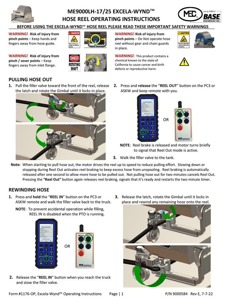
PULLING HOSE OUT with HANDS-FREE REEL OUT™
1. Pull the filler valve toward the front of the reel, release
the latch and rotate the Gimbal until it locks in place.
2. Press and release the “REEL OUT” button on the PC3 or
ASKW and keep remote with you.
NOTE: Reel brake is released and motor turns briefly
to signal that Reel Out mode is active.
3.
Walk the filler valve to the tank.
Note: As hose is pulled out, the motor drives the reel up to speed for one revolution. Slowing down, stopping or not
pulling the hose for two minutes cancels Reel Out mode and turns reel braking on. Pressing the “Reel Out” button
again releases reel braking, turns the motor briefly to signal that Reel Out is active and restarts the two minute timer.
REWINDING HOSE
1. Press and hold the “REEL IN” button on the PC3 or
ASKW remote and walk the filler valve back to the truck.
2. Release the “REEL IN” button when you reach the truck
and stow the filler valve.
3. Release the latch, rotate the Gimbal until it locks in
place and rewind any remaining hose onto the reel.
OR
OR

ME9000LH-17/25 EXCELA-WYND™HOSE REEL (Patent Pending)
INSTALLATION AND OPERATING INSTRUCTIONS
Form #1176, Excela-Wynd™ Hose Reel IOM Page | 15 Rev B12/1/21
TIPS for Operating the EXCELA-WYND™Hose Reel
•Your service provider can adjust rewind speed between 1.5 and 3.5 MPH to match driver or seasonal needs.
•Avoid twisting the hose excessively to prevent binding on the reel and assure reliable automatic loading.
•If you have a loss of truck battery power to the reel controller while the hose is pulled out, such as when using the
emergency shut down, when the power is restored the hose reel speed controller may temporarily rewind at a different
speed. Once the hose is fully rewound on the reel, turning the truck ignition off and back on will reset rewind speed.
To raise the cover -
Pull the front detent
pin, push the front of
the cover to the left to
release it, and rotate
it upward. Latch and
pin cover when done.
To remove the cover -
Pull both detent pins,
push the cover to the
left to release it, and
lift it upward. Latch
and pin cover when
done.
To use the manual crank - (Remove crank from
storage pouch and remove red safety cap)
1) Insert the safety collar into the axle.
2) Push in and turn to engage drive pin.
When the hose is loaded, remove crank, replace
safety cap and place in storage pouch.
Note: Turning the truck ignition off releases the
reel brake making it easier to turn.
TROUBLESHOOTING
PROBLEM
POSSIBLE CAUSES AND SOLUTIONS
•The reel brake doesn’t release when pressing REEL OUT
•
The reel won’t turn at all when pressing REEL IN
•
The reel brake engages during REEL OUT or the reel stops
rewinding during REEL IN once you’re a distance from the truck
•The batteries in the remote may be too low to transmit or may
transmit only a short distance - Recharge or replace batteries.
•
The truck ignition may be off, removing power from the
controller - Make sure the ignition is on and the brake is set.
•
The ciruit breaker on the BASE Engineering controller enclosure
may have tripped - Check circuit breaker and reset, if tripped.
•The reel stops turning while pressing
REEL IN
(Rewind)
•An extremely high motor load may have triggered the over-
current protection - It will automatically reset after (5) seconds.
•
The hose may be stuck on an obstruction - Check for and clear
any obstructions.
•
The hose may have bound in the reel due to excessive twisting -
If the hose is bound or not evenly layered on the reel, pull out
any hose that is bound, remove excessive twist and rewind hose.
This manual suits for next models
1
Table of contents
Other base engineering Tools manuals
