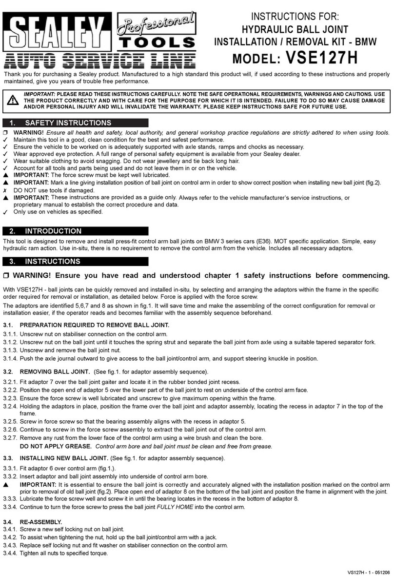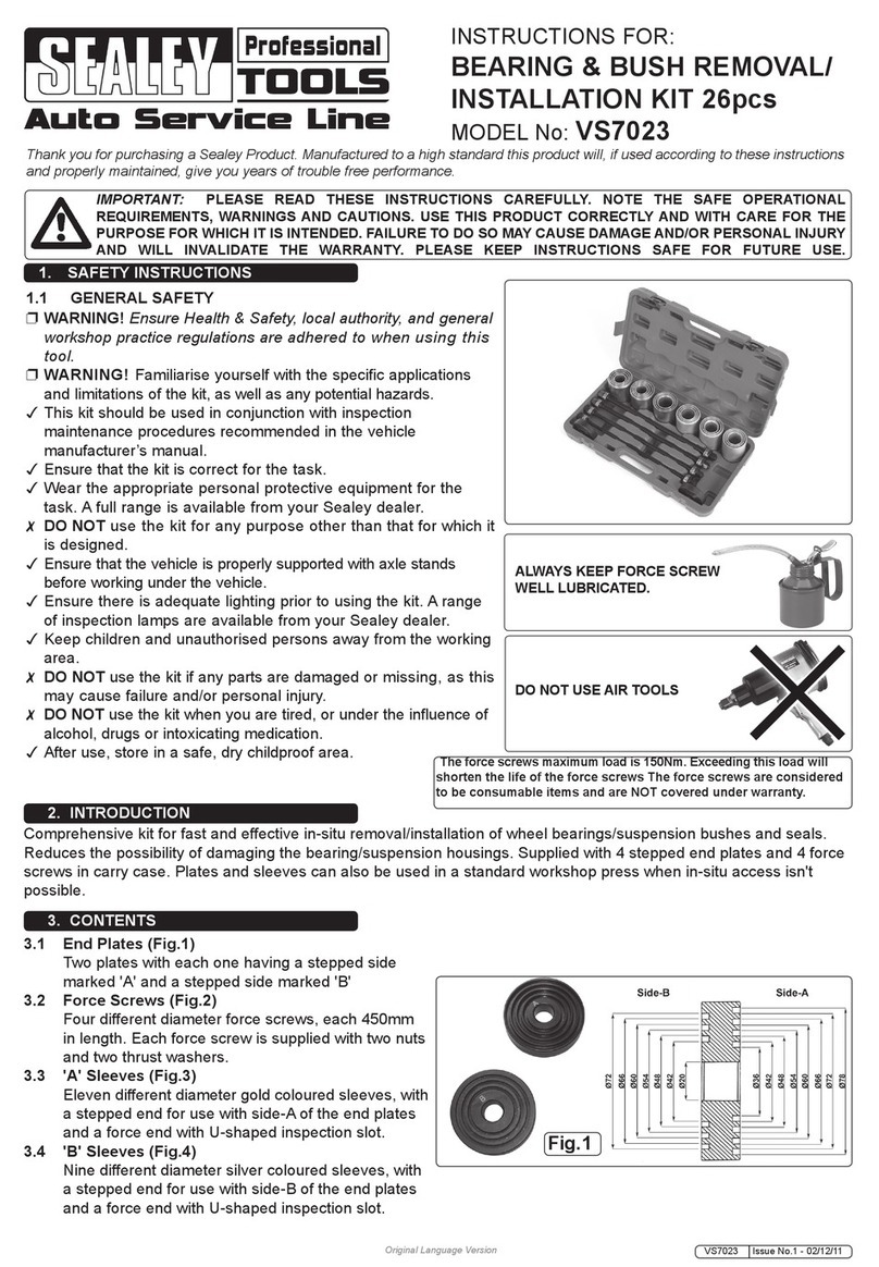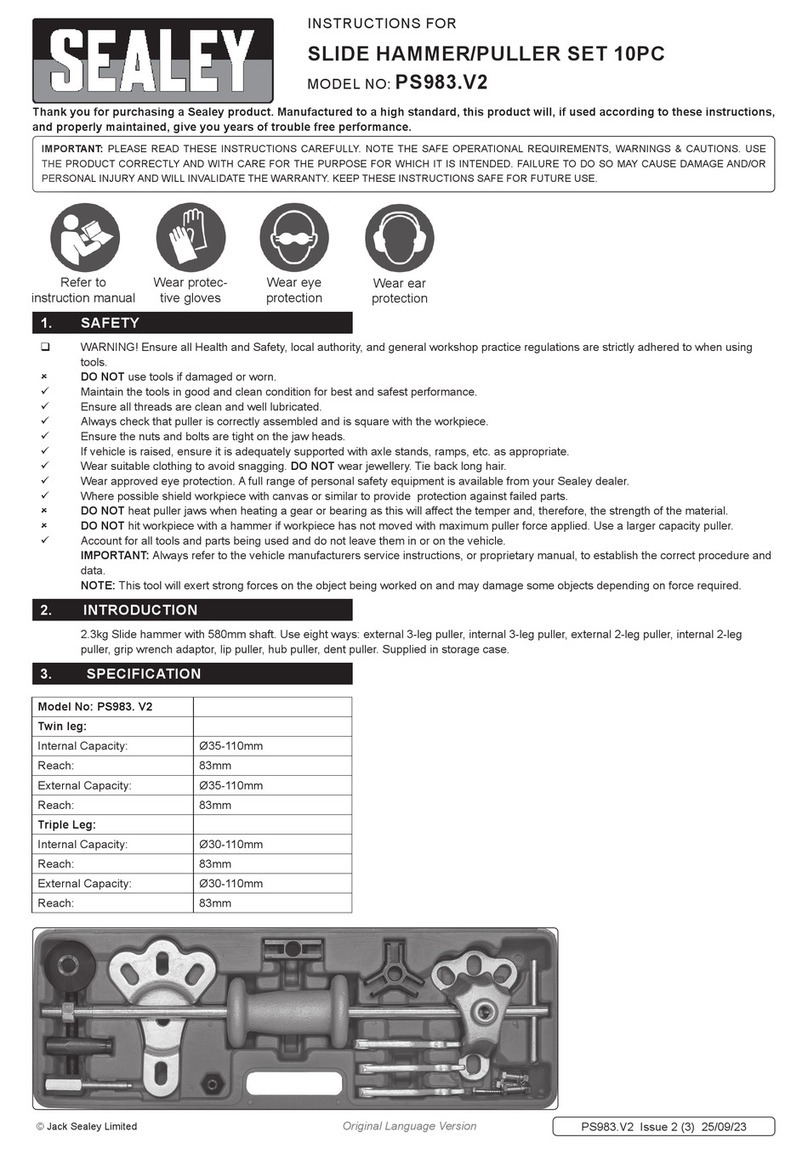
4.1. Place Frame (g.3.A1) into Frame (g.3.A2) insert Bolt (g.2.6) and place at washer (g.2.12) onto Bolt. Fasten frame using lock
nut (g.2.11).
4.2. Remove and retain lock nut (g.2.9) and at washer (g.2.10) from axle (g.4.B). Stand frame assembly (g.4.A) upright.
Slide each axle (g.4.B) through both ends of frame (g.4.A).
4.3. Slide wheels (g.5.C) onto ends of each axles (g.5.B), with the wheel valve stems facing outward. Fasten each wheel to
axle using at washers (g.2.10) and lock nuts (g.2.9). DO NOT over tighten.
4.4. Insert the end of crank handle (g.6.E) through crank hub of frame (g.6.A).
4.5. Attach the rst hose reel (g.7.D) to the roller (g.7.I), on the end with the crank
handle stem, using 6 bolts (g.2.5).
4.6. Place hose reel (g.8.D) into frame assembly (g.8.A). Insert end of crank stem from
hose reel (g.8.D) onto crank handle (g.8.E). Align crank handle (g.8.E) mounting holes
with crank stem mounting holes.
4.7. (g.9.) Insert bolt (g.2.3) through inside hole of crank stem and crank handle
hole, Place at washer (g.2.10) onto bolt (g.2.3) fasten with lock nut (g.2.11).
Tighten securely.
4.8. Attach hose coupling end of hose reel (g.10.D) to frame (g.10.A), using
U-bracket. Fasten U-bracket to frame with carriage bolts (g.2.3) and lock
nuts (g.2.11). Tighten securely.
4.9. Place handle (g.11. F) onto vertical posts of frame (g.11. A). Align mounting
holes. Slide bolt (g.2.2) through mounting holes and place at washer (g.2.12)
onto bolt (g.2.2). Fasten handle (g.11. F) using lock nut (g.2.11).
4.10. Attach basket (g.12.H) to handle (g.12.F). Place at washer (g.2.8)
onto bolt (g.2.4) and slide both bolts through mounting holes of handle (g.12.F).
Place basket (g.12.H) mounting tabs onto bolts (g.2.4) then place at washer (g.2.8) onto both bolts. Fasten basket using hex
nuts (g.2.7).
g.4
g.3 g.5
g.6
g.7
g.8
g.10
g.11
g.9
HRCHD Issue 1 28/08/19
Original Language Version
© Jack Sealey Limited

