Basta Boatlifts Solo 26 User manual

11/21
L392-0113, REV C
866-GO-BASTA
www.gobasta.com
Copyright 2021 Basta Inc.
©
Basta Boatlifts Bellevue WA 98005 USA
Solø
Wide Series Canopies
OWNER'S MANUAL
™

Thank you for purchasing a Basta Boatlifts Solø™ Canopy. We feel you have made a wise
choice and hope that you always remain completely satisfied with its beauty and durability.
Please take a moment and read through this entire manual before beginning assembly.
There are many parts that look similar but are different lengths, including hardware. Lay out the
parts prior to assembly with identical items grouped together.
Make sure that all pieces are assembled in the proper sequence or complications may result.
Be certain you know exactly what's going to happen during each step. There are large parts
and therefore we emphasize CAUTION should be exercised to ensure your safety at all times.
The canopy must be assembled on a day when the weather is calm and dry. We recommend
that you hire a professional or have help when assembling your canopy.
THANK YOU
INTRODUCTION
2
NOTES:
DEALER:
PURCHASE DATE:
PHONE:
1 - 866 - GO BASTA (1 - 866 - 462 - 2782) www.gobasta.com
FABRIC TYPE:
FABRIC COLOR:
MODEL:
Sunbrella™
Vinyl
Other:
INSTALLED BY: PHONE:DATE:
You will find the following tools helpful in the assembly of your Basta Boatlifts Solø™ canopy:
7/16” combination end wrench
1/2” combination end wrench
9/16” combination end wrench
3/4” combination end wrench
3/16” allen wrench
TOOLS REQUIRED FOR ASSEMBLY
GENERAL NOTES
1. Refer to pages 5 through 9 to identify the canopy parts. The various similar looking rafters
and rails can quickly be identified with a tape measure.
2. For best results the canopy should be assembled on a reasonably level surface.
3. Before starting assembly, lay out components in their approximate positions.
4. The lacing rails and rafters are always installed with the grooved face up.
5. Over-tightening the fasteners may bend or distort the aluminum parts.
6. After completing the assembly of the canopy frame and before installing the canvas, go back
and recheck each of the fasteners for tightness. A few days later, check the fasteners again.
7. After any period of high wind, check the fasteners for tightness, especially the bolts that
tension the leg clips. Check the canvas for any rips or loose lacing.
3
SPECIFICATIONS
Illustration is typical.
Dimensions are approximate.
tape measure
carpenter's level
2 pieces of 2 X 4 X 12' lumber
strong cord
Model 26w 30w 33w 39w
Nominal Length 26' 30' 33' 39'
Nominal Width 12' 12' 12' 12'
Leg Height (Dimension A) Leg Height for all canopies is from 86 1/2” – 149”
150
inches
150
inches
47 inches
312 inches

4
WIDE 12 FOOT WIDTH Solø™ CANOPY TYPES
Basta Boatlifts Solø™ canopies are modular. The wide Solø 26™ is shipped as five kits -
three kits containing the long extrusions, one with the smaller pieces and hardware and
one containing the canvas/vinyl. The wide Solø 30™, Solø 33™ and Solø 39™ each
add a kit for the center section with both extrusions and hardware.
13 foot section 13 foot section 13 foot section
The two extrusion kits for the wide 26 foot Solø™ canopy are identical.
Solø 26™
Solø 39™
Solø 30™
Solø 33™
The extrusion kits for the ends of the wide 39 foot Solø™ canopy are identical. The center
kit has a different ridge rail, but the other parts are the same as in the end kits.
11 foot section 11 foot section 11 foot section
11 foot section 8 foot
section 11 foot section
13 foot section 13 foot section
The extrusion kits for the ends of the wide 33 foot Solø™ canopy are identical. The center
kit has a different ridge rail, but the other parts are the same as in the end kits.
The extrusion kits for ends of the wide 30 foot Solø™ canopy are identical, but the center
kit is different.
5
5/16 - 18 x 1 3/4 hex head cap screw
5/16 - 18 x 3 hex head cap screw
5/16 - 18 x 4 hex head cap screw
1/4 - 20 x 1 hex head cap screw
5/16 - 18 x 4 1/2 hex head cap screw
5/16 - 18 x 2 flat socket head cap screw
5/16 - 18 x 2 carriage bolt
1/2 - 13 x 1 1/4 hex head set screw
3/8 - 16 x 1 carriage bolt
3/8 - 16 x 3 3/4 hex head cap screw
5/16 x 1 OD flat washer
3/8 - 16 flange nut
5/16 - 18 flange nut
3/8 - 16 lock nut
1/4 - 20 lock nut
3/8 flat washer
5/8 - 11 x 1 1/2 hex head set screw
Lower inner leg for foot pad
Outer leg
Inner leg
Corner rafter
Short diagonal rafter
Side rafter
Long diagonal rafter
End rail
Short side rail
Short ridge rail
Long side rail
Long ridge rail
Short center ridge rail
Long center ridge rail
End lacing rail
Short side lacing rail
Extra short side rail
Extra short center ridge rail
Short center diagonal rafter
Extra short side lacing rail
Leg clip
Center rafter clip
Corner rafter clip
Ridge rafter clip
Medium rafter clip
Rafter spacer
Corner splice plate
Straight splice plate
Bungee clip
Rafter strap
End rafter
Long side lacing rail
Hill holder foot
Insert cap, 2 x 2 - 1/2
Ridge corner pads
Lacing (70' roll)
Lacing (20' roll)
Canvas or vinyl cover
S103-0408
S103-0413
S103-0417
S103-0305
S103-0419
S118-0409
S123-0409
S166-6711
S123-0505
S103-0516
S313-2001
S342-7008
S342-7007
S362-0008
S362-0006
S313-0008
S166-6812
K200-0012
W141-0003
K250-0005
K254-0005
K254-0008
K254-0007
K254-0006
K256-0007
K256-0002
K256-0010
K256-0004
K256-0008
K256-0006
K256-0009
K257-0004
K257-0002
K256-0011
K256-0012
K254-0002
K257-0005
K258-0008
K258-0002
K258-0003
K258-0004
K258-0017
K258-0016
K258-0005
K258-0006
K258-0007
K259-0001
K254-0023
K257-0003
W116-0004
F730-0019
C350-0001
S952-0002
S952-0003
see page 2
10
18
24
8
6
20
3
8
4
8
18
4
47
8
8
16
0
0
4
4
4
0
12
4
2
0
0
4
2
0
0
2
0
0
0
0
0
4
2
4
6
6
18
4
2
16
6
2
4
0
4
2
2
0
1
14
26
40
12
10
28
5
12
6
12
30
6
113
12
12
24
2
2
6
6
6
0
20
6
2
6
2
0
0
1
1
2
0
0
0
0
0
6
4
4
10
8
30
4
4
20
10
2
6
2
6
2
2
4
1
DESCRIPTION
ITEM # QTY QTY QTY PART #
Solø 26 Solø 30 Solø 39
WIDE 12 FOOT WIDTH Solø CANOPIES
14
26
40
12
10
28
5
12
6
12
30
6
113
12
12
24
2
2
6
6
6
6
20
0
2
6
2
0
0
1
0
2
6
2
1
0
0
6
4
4
10
8
30
4
4
20
10
2
0
2
6
2
2
2
1
14
26
40
12
10
28
5
12
6
12
30
6
113
12
12
24
2
2
6
6
4
4
20
0
2
6
2
0
0
1
0
2
4
2
1
4
2
6
4
4
10
8
30
4
4
20
10
2
0
2
6
2
2
2
1
QTY
Solø 33
1
2
3
4
5
6
7
8
9
10
11
12
13
14
15
16
17
18
19
20
21
22
23
24
25
26
27
28
29
30
31
32
33
34
35
36
37
38
39
40
41
42
43
44
45
46
47
48
49
50
51
52
53
54
55

4
WIDE 12 FOOT WIDTH Solø™ CANOPY TYPES
Basta Boatlifts Solø™ canopies are modular. The wide Solø 26™ is shipped as five kits -
three kits containing the long extrusions, one with the smaller pieces and hardware and
one containing the canvas/vinyl. The wide Solø 30™, Solø 33™ and Solø 39™ each
add a kit for the center section with both extrusions and hardware.
13 foot section 13 foot section 13 foot section
The two extrusion kits for the wide 26 foot Solø™ canopy are identical.
Solø 26™
Solø 39™
Solø 30™
Solø 33™
The extrusion kits for the ends of the wide 39 foot Solø™ canopy are identical. The center
kit has a different ridge rail, but the other parts are the same as in the end kits.
11 foot section 11 foot section 11 foot section
11 foot section 8 foot
section 11 foot section
13 foot section 13 foot section
The extrusion kits for the ends of the wide 33 foot Solø™ canopy are identical. The center
kit has a different ridge rail, but the other parts are the same as in the end kits.
The extrusion kits for ends of the wide 30 foot Solø™ canopy are identical, but the center
kit is different.
5
5/16 - 18 x 1 3/4 hex head cap screw
5/16 - 18 x 3 hex head cap screw
5/16 - 18 x 4 hex head cap screw
1/4 - 20 x 1 hex head cap screw
5/16 - 18 x 4 1/2 hex head cap screw
5/16 - 18 x 2 flat socket head cap screw
5/16 - 18 x 2 carriage bolt
1/2 - 13 x 1 1/4 hex head set screw
3/8 - 16 x 1 carriage bolt
3/8 - 16 x 3 3/4 hex head cap screw
5/16 x 1 OD flat washer
3/8 - 16 flange nut
5/16 - 18 flange nut
3/8 - 16 lock nut
1/4 - 20 lock nut
3/8 flat washer
5/8 - 11 x 1 1/2 hex head set screw
Lower inner leg for foot pad
Outer leg
Inner leg
Corner rafter
Short diagonal rafter
Side rafter
Long diagonal rafter
End rail
Short side rail
Short ridge rail
Long side rail
Long ridge rail
Short center ridge rail
Long center ridge rail
End lacing rail
Short side lacing rail
Extra short side rail
Extra short center ridge rail
Short center diagonal rafter
Extra short side lacing rail
Leg clip
Center rafter clip
Corner rafter clip
Ridge rafter clip
Medium rafter clip
Rafter spacer
Corner splice plate
Straight splice plate
Bungee clip
Rafter strap
End rafter
Long side lacing rail
Hill holder foot
Insert cap, 2 x 2 - 1/2
Ridge corner pads
Lacing (70' roll)
Lacing (20' roll)
Canvas or vinyl cover
S103-0408
S103-0413
S103-0417
S103-0305
S103-0419
S118-0409
S123-0409
S166-6711
S123-0505
S103-0516
S313-2001
S342-7008
S342-7007
S362-0008
S362-0006
S313-0008
S166-6812
K200-0012
W141-0003
K250-0005
K254-0005
K254-0008
K254-0007
K254-0006
K256-0007
K256-0002
K256-0010
K256-0004
K256-0008
K256-0006
K256-0009
K257-0004
K257-0002
K256-0011
K256-0012
K254-0002
K257-0005
K258-0008
K258-0002
K258-0003
K258-0004
K258-0017
K258-0016
K258-0005
K258-0006
K258-0007
K259-0001
K254-0023
K257-0003
W116-0004
F730-0019
C350-0001
S952-0002
S952-0003
see page 2
10
18
24
8
6
20
3
8
4
8
18
4
47
8
8
16
0
0
4
4
4
0
12
4
2
0
0
4
2
0
0
2
0
0
0
0
0
4
2
4
6
6
18
4
2
16
6
2
4
0
4
2
2
0
1
14
26
40
12
10
28
5
12
6
12
30
6
113
12
12
24
2
2
6
6
6
0
20
6
2
6
2
0
0
1
1
2
0
0
0
0
0
6
4
4
10
8
30
4
4
20
10
2
6
2
6
2
2
4
1
DESCRIPTION
ITEM # QTY QTY QTY PART #
Solø 26 Solø 30 Solø 39
WIDE 12 FOOT WIDTH Solø CANOPIES
14
26
40
12
10
28
5
12
6
12
30
6
113
12
12
24
2
2
6
6
6
6
20
0
2
6
2
0
0
1
0
2
6
2
1
0
0
6
4
4
10
8
30
4
4
20
10
2
0
2
6
2
2
2
1
14
26
40
12
10
28
5
12
6
12
30
6
113
12
12
24
2
2
6
6
4
4
20
0
2
6
2
0
0
1
0
2
4
2
1
4
2
6
4
4
10
8
30
4
4
20
10
2
0
2
6
2
2
2
1
QTY
Solø 33
1
2
3
4
5
6
7
8
9
10
11
12
13
14
15
16
17
18
19
20
21
22
23
24
25
26
27
28
29
30
31
32
33
34
35
36
37
38
39
40
41
42
43
44
45
46
47
48
49
50
51
52
53
54
55

6
WIDE 12 FOOT WIDTH CANOPY EXTRUSION IDENTIFICATION
Solø 26™
Long Side
Rails (4x)
End Rails (2x)
Side Rafters (12x)
Corner Rafters (4x)
Long Diagonal Rafters (4x)
Long Side Lacing Rails (4x)
End Lacing Rails (2x)
Long Ridge Rail (2x)
147.75"
154.5"
81.125"
375 cm
392 cm
206 cm
82.25"
108.75"
110.125"
153.25"
141.0"
209 cm
276 cm
280 cm
389 cm
358 cm
Solø 30™
Short Ridge Rail (2x)
Short Side Rails (4x)
Extra Short
Side Rails (2x)
End Rails (2x)
Side Rafters (20x)
Corner Rafters (4x)
Short Diagonal Rafters (4x)
Short Center Diagonal Rafters (4x)
Short Side Lacing Rails (4x)
Extra Short Side Lacing Rails (2x)
End Lacing Rails (2x)
Extra Short Center Ridge Rail (1x)
82.25"
108.75"
97.25"
129.25"
141.0"
209 cm
276 cm
247 cm
328 cm
358 cm
147.75"
130.5"
57.125"
375 cm
331 cm
145 cm
94.75"
94.75"
241 cm
241 cm
93.125"
93.5"
237 cm
237 cm
7
WIDE 12 FOOT WIDTH CANOPY EXTRUSION IDENTIFICATION
Solø 33™
Short Ridge Rail (2x)
Short Side Rails (6x)
End Rails (2x)
Side Rafters (20x)
Corner Rafters (6x)
Short Diagonal Rafters (6x)
Short Side Lacing Rails (6x)
End Lacing Rails (2x)
Short Center Ridge Rail (1x)
82.25"
108.75"
97.25"
129.25"
141.0"
209 cm
276 cm
247 cm
328 cm
358 cm
147.75"
130.5"
57.125"
375 cm
331 cm
145 cm
130.5" 331 cm
Solø 39™
Long Side
Rails (6x)
154.5"
154.5"
392 cm
392 cm
End Rails (2x)
End Lacing Rails (2x)
Long Ridge Rail (2x)
147.75"
81.125"
375 cm
206 cm
141.0" 358 cm
Long Center
Ridge Rail (1x)
Side Rafters (20x)
Corner Rafters (6x)
Long Diagonal Rafters (6x)
Long Side Lacing Rails (6x)
82.25"
108.75"
110.125"
153.25"
209 cm
276 cm
280 cm
389 cm
End Rafters (2x)
84.313" 214 cm
End Rafters (2x)
84.313" 214 cm
End Rafters (2x)
84.313" 214 cm
End Rafters (2x)
84.313" 214 cm
23
21
48
24
49
32
23
21
22
36
33
37
32
48
23
21
22
48
33
32
23
21
48
24
49
32
35
27
34
26
25
29
28
25
31
29
28
25
30
27
26
25

9
CONNECTOR EXTRUSIONS
Bungee Clip
Straight Splice Plate
Center Rafter Clip
Leg Clip
Corner Splice Plate
Corner Rafter Clip
Ridge Rafter Clip
Rafter Strap
8
WIDE 12 FOOT WIDTH Solø™ CANOPY HARDWARE
5/16 - 18 x 1 3/4 hex head cap screw
5/16 - 18 x 3 hex head cap screw
5/16 - 18 x 4 hex head cap screw
5/16 - 18 x 4 1/2 hex head cap screw
1/4 - 20 x 1 hex head cap screw
5/16 - 18 x 2 flat socket head cap screw
5/16 - 18 x 2 carriage bolt
1/2 - 13 x 1 1/4 hex head set screw
3/8 - 16 x 1 carriage bolt
3/8 - 16 x 3 3/4 hex head cap screw
5/16 x 1 OD flat washer
3/8 - 16 flange nut
5/16 - 18 flange nut
3/8 - 16 lock nut
1/4 - 20 lock nut
3/8 flat washer
1/2 hex head set screw5/8 - 11 x 1
1
2
3
4
5
6
7
8
9
10
11
12
13
14
15
16
17
S103-0408
S103-0413
S103-0417
S103-0419
S103-0305
S118-0409
S123-0409
S166-6711
S123-0505
S103-0516
S313-2001
S342-7008
S342-7007
S362-0008
S362-0006
S313-0008
S166-6812
8
16
4
2
8
20
1
8
4
8
18
4
47
8
8
16
0
12
24
8
4
12
24
2
12
6
12
30
6
74
12
12
24
2
DESCRIPTION
ITEM # QTY QTY PART #
Solø 26 Solø 30+
ridge rail to upper rafter clips
single rafters to rafter clips
double rafters to rafter clips
rafter strap to rafters
leg clips
splice plates
rafter strap tensioner
outer leg to lift leg
inner leg to outer leg
leg clip to inner leg
side rafters
as needed
as needed
leg clip to inner leg
leg clip
leg clip to inner leg
forward leg foot
WHERE USED
67
5
8
9
12 13
4
2
1
3
1
2
3
4
5
6
10
14
15
16
11
17
Medium Rafter Clip
tappednot
tapped
Rafter Spacer
39 47 42 40
444543
46 41 38
?SEE PAGE 5

9
CONNECTOR EXTRUSIONS
Bungee Clip
Straight Splice Plate
Center Rafter Clip
Leg Clip
Corner Splice Plate
Corner Rafter Clip
Ridge Rafter Clip
Rafter Strap
8
WIDE 12 FOOT WIDTH Solø™ CANOPY HARDWARE
5/16 - 18 x 1 3/4 hex head cap screw
5/16 - 18 x 3 hex head cap screw
5/16 - 18 x 4 hex head cap screw
5/16 - 18 x 4 1/2 hex head cap screw
1/4 - 20 x 1 hex head cap screw
5/16 - 18 x 2 flat socket head cap screw
5/16 - 18 x 2 carriage bolt
1/2 - 13 x 1 1/4 hex head set screw
3/8 - 16 x 1 carriage bolt
3/8 - 16 x 3 3/4 hex head cap screw
5/16 x 1 OD flat washer
3/8 - 16 flange nut
5/16 - 18 flange nut
3/8 - 16 lock nut
1/4 - 20 lock nut
3/8 flat washer
1/2 hex head set screw5/8 - 11 x 1
1
2
3
4
5
6
7
8
9
10
11
12
13
14
15
16
17
S103-0408
S103-0413
S103-0417
S103-0419
S103-0305
S118-0409
S123-0409
S166-6711
S123-0505
S103-0516
S313-2001
S342-7008
S342-7007
S362-0008
S362-0006
S313-0008
S166-6812
8
16
4
2
8
20
1
8
4
8
18
4
47
8
8
16
0
12
24
8
4
12
24
2
12
6
12
30
6
74
12
12
24
2
DESCRIPTION
ITEM # QTY QTY PART #
Solø 26 Solø 30+
ridge rail to upper rafter clips
single rafters to rafter clips
double rafters to rafter clips
rafter strap to rafters
leg clips
splice plates
rafter strap tensioner
outer leg to lift leg
inner leg to outer leg
leg clip to inner leg
side rafters
as needed
as needed
leg clip to inner leg
leg clip
leg clip to inner leg
forward leg foot
WHERE USED
67
5
8
9
12 13
4
2
1
3
1
2
3
4
5
6
10
14
15
16
11
17
Medium Rafter Clip
tappednot
tapped
Rafter Spacer
39 47 42 40
444543
46 41 38
?SEE PAGE 5

10
1. Install the 3/8 x 1” carriage bolts and nuts on
the outer legs and leave slightly loose.
2. Install the inner legs with the end with two holes
facing up. The carriage bolt heads slide in the slots.
3. Install 1/2 x 1 1/4" hex head set screws into the
nuts welded on the outer legs. Tighten until they
are flush with the inner surface of the leg.
4. Orient the canopy legs with the slot in the inner
legs facing forward or aft.
5. Slide the canopy legs over the lift legs. The
bottoms of the canopy legs should rest directly on the
lift’s leg sockets. Tighten the 1/2 x 1 1/4 set screws.
LEG ASSEMBLY
INNER
LEG
OUTER
LEG
3/8 x 1"
carriage
C arriage bolts face forward or aft on
lift frame.
11
ATTACHMENT TO LIFT
6. Raise the canopy legs until their tops are level (horizontal) by loosening the carriage bolts
slightly one at a time and sliding the inner legs. A string, water or laser level will be very helpful
here. Recheck the legs for plumb and adjust as necessary.
7. Lash a pair of 2x4s tightly to the canopy legs with strong cord as shown below. They will make
the canopy installation much safer and easier.
8. Adjust the lift legs as necessary to assure that the canopy legs are plumb (vertical).
9. If the canopy includes six legs, the final pair is installed after the canopy frame is mounted.
1/2 x 1 1/4"
hex head set screws
1/2 x 1 1/4"
hex head set screws
TEMPORARY
WOOD SUPPORT
Two Holes
canopy leg
leg socket

13
pages 21 & 22
pages 16, 17, 21 & 22 page 10
12
pages 15 & 18
pages 22 - 24page 25

13
pages 21 & 22
pages 16, 17, 21 & 22 page 10
12
pages 15 & 18
pages 22 - 24page 25

14
SPECIAL NOTES FOR Solø™ 30, 33 & 39 CANOPY FRAMES
1. These Solø™ canopies add a center extension section to a Solø™ 26 canopy.
2. The center section pieces are added in as the side rail and ridge rail assemblies are built. The
same splice plates and rafter clips are used to connect the additional pieces.
3. The pair of ridge rafter clips near the center of the canopy that do not connect any ridge rails
together are allowed to 'float' in the ridge rail dovetail slots without being bolted to the rails. Note
that the floating rafter clips will not be positioned at the exact center of the canopy.
15
END RAIL ASSEMBLY
The "end" rail assemblies are identical. The rails
themselves are symmetrical, so there is no need
to orient them in any particular direction before
starting assembly.
1. Slide four Bungee Clips and a Medium Rafter Clip
into each rail dovetail and space them evenly as
shown below.
2. Slip an 'end' lacing rail with grooves facing up
into the clips installed in Step 1 and center it.
Repeat for the other end rail.
3. Slide the four 'corner' Splice Plates into the
dovetails as shown at left and secure them with
one flat head bolt and flange nut each. Note that
they must be oriented as shown at left.
LONG
GROOVE UP
LACING RAIL
END RAIL
BUNGEE CLIP
CORNER SPLICE
PLATE
END RAIL
END RAIL
5/16 x 2"
flat head
these rafter
clips 'float'
STAKE FEET
TO GROUND
AFT
END
FORWARD
END
LACING
RAILS
42 MEDIUM RAFTER CLIP x 2
44 CORNER SPLICE PLATE x 4
46 BUNGEE CLIP x 8
FORWARD LEGS FOR Solø™ 30, 33 & 39
1/2 x 1 1/4"
set screws
5/8 x 1 1/2"
set screw
OUTER
LEG
ROUND
INNER LEG
HILL HOLDER FOOT
4. The pair of canopy legs that are not
attached to the lift have flat feet that sit on the
ground. These legs are attached to the canopy
frame after it is installed on the lift as shown
on page 25. Attach the canopy leg clips and
legs to the canopy side rails in the desired
location. Extend them down to the lakebed.
Use a level on the legs to determine plumb
and position the foot pad. Raise or remove the
canopy leg, stake the foot pad in position, then
over-sleeve the foot pad leg with the canopy
leg. Secure all fasteners.

16
SIDE RAIL ASSEMBLY - Solø 26 SIDE RAIL ASSEMBLY - Solø 30, 33, 39
1. Slide two Bungee Clips and a Medium Rafter Clip into the inner dovetail slot in each of the side
rails. A Medium Rafter Clip is the same as a Corner Rafter Clip, but without threads in its side holes.
2. Slide the lacing rails into the clips. Slip the Corner Rafter Clips into the inner dovetail slots as
shown below.
3. Slide the Center Rafter Clips into the inner dovetail slots and the straight splice plates into the
outer dovetail slots of a left and a right side rail as shown. Secure with two screws and nuts each.
4. Mate each pair of side rails as shown. Secure with two more screws and nuts each.
1. Longer canopies have three piece side rails instead of two piece. They are similarly assembled.
2. The side lacing rails may have a hole that is offset from the center. The red bars in the
illustrations show which direction the lacing rails are installed.
GROOVE UP
SIDE
RAIL
SIDE
RAIL
CORNER
RAFTER
CLIP
BUNGEE
CLIP
CORNER
RAFTER
CLIP
SIDE
LACING
RAIL
CENTER
RAFTER
CLIP
STRAIGHT
SPLICE
PLATE
17
42
40
40
42
46
46
46
46
39
CENTER RAFTER CLIP
45
GROOVE UP
SIDE
RAIL
SIDE
RAIL
CORNER
RAFTER
CLIP
SIDE
LACING
RAIL
CORNER
RAFTER
CLIP
CENTER
RAFTER
CLIP
5/16 x 2"
flat head
42
40
40
42
46
46
46
46
45
Solø 26 Solø 30, 33, 39
5/16 x 2"
flat head
MEDIUM
RAFTER
CLIP
40
46
42
39
39
45
46
39
42
46
39
45
? ?
SEE PAGE 5 SEE PAGE 5
FORWARD
FORWARD
FORWARD
FORWARD
FORWARD
short distancelong distance
30’
33’
39’
26’
see STEP 2 next page
LACING RAILS
33 3337
33 3333
49 4949
49 49
DATA ON PAGES 6 & 7

18
RIDGE RAIL ASSEMBLY
1. Slide two Rafter Clips into the dovetail slots of one of the ridge rails as shown in the drawing
above. Fasten them to the ridge rail with two nuts and bolts.
2. Line up the other ridge rail and slide it on to the Rafter Clips just installed. Fasten the assembly
together with two more nuts and bolts. There is no preferred direction for the bolts.
3. Install the Rafter Clips on the ends of the ridge rails as shown above. Note that the bolts are
installed in the two center holes of the clips.
RIDGE
RAFTER
CLIP
RIDGE
RAIL
RIDGE RAFTER
CLIPS (BOTH SIDES)
RIDGE
RAIL
RIDGE
RAIL
5/16 x 1 ¾"
hex head
SEE PAGE 17 FOR ADDITIONAL
INFORMATION ON
Solø™ 30, 33 and 39
CONSTRUCTION.
NOTE CHAMFER ON ALL
RIDGE RAFTER CLIPS
19
CORNER ASSEMBLY
1. Position one of the completed end rail
assemblies so that the free ends of its Splice
Plates can be inserted into the outer dovetail
slots of the assembled side rails.
2. Install a bolt through the end rail and Splice
Plate into the threaded portion of the Corner
Rafter Clip (shown at left - Bolt A). Be careful to
avoid cross threading - starting with a small gap
between the end and side rails will allow you to
see and more easily align the bolt to the Corner
Rafter Clip.
3. Insert a bolt in the unfilled bottom hole of the
Splice Plate through the side rail and Rafter
Clip (shown at left - Bolt B). Secure it with a nut
as shown at lower left. Note that the upper hole
is not used.
4. Repeat for the other three corners.
5. Position a corner rafter as shown at left. Its
grooved face should be facing up. Adjust the
side lacing rail position as necessary to allow
the rafter fixing bolt to be inserted. The bolt
should go through the hole in the Rafter Clip
and the hole at the end of the lacing rail. Install
the nut on the bolt finger tight.
6. The rafter may be swung down against the
side rail.
7. Repeat for the other three corner rafters.
END RAIL SIDE RAIL
CORNER RAFTER
CORNER
SPLICE
PLATE
CORNER
RAFTER
CLIP
BUNGEE
CLIP
END
LACING
RAIL
BOLT
ABOLT
B
5/16 x 2"
flat head 5/16 x 2"
flat head
5/16 x 3"
hex head
no bolt
RIDGE
RAFTER
CLIP
5/16 x 1 ¾"
hex head
LEAVE NUTS LOOSE
ON END CLIPS ONLY
RIDGE
RAFTER
CLIP
no bolts - clips “float”
NO BOLTS -THESE
CLIPS “FLOAT”
RIDGE
RAIL
RIDGE
RAIL
RIDGE
RAIL
Solø 26
Solø 30, 33, 39
STEP
6

20 21
SIDE RAFTER ASSEMBLY
SIDE RAFTER ASSEMBLY
1. Start adding in the vertical side rafters in pairs using mostly
5/16 x 4” bolts - the bolts that also secure the Rafter Straps
are longer: 5/16 x 4 1/2”. All of the rafters are installed with
their grooved faces facing up.
2.The rafters in each pair are held apart by spacer tubes and
washers placed over the inner three bolts. The washers are
important because they prevent the spacers from damaging
the rafters when tightened. The rafter pairs form trusses that
increase the strength of the canopy.
3. Each pair of rafters has a Rafter Strap attached. The Rafter
Straps are used to resist the tendency of the side rails to bow
outward when installed on the lift. Install them as shown at left.
Tighten the RafterSstrap carriage bolts finger tight.
RIDGE
RAFTER
CLIPS
RAFTER
STRAP
RAFTER
STRAP
5/16 x 2"
carriage
5/16 x 4"
hex head
5/16 x 4½"
hex head
5/16 x 4½"
hex head
39’33’30’26’
SIDE RAILS
5/16 x 4"
hex head
MEDIUM RAFTER CLIP
SIDE
RAFTERS
5/16 x 4"
hex head
RIDGE RAIL ASSEMBLY
4. Have an assistant hold the completed ridge assembly in its installed position. Swing the corner
rafters up and bolt them to the ridge rafter clips as shown below right.
SIDE RAFTERS
5/16 x 4½" (longer)
hex head
5/16 x 4"
hex head
5/16 x 4"
hex head
SIDE
RAFTERS
SIDE
RAFTERS
CENTER RAFTER CLIP
SIDE
RAILS
RIDGE
RAILS
BOLTS THRU HOLE
IN LACING RAIL
ALL DOUBLE SIDE RAIL SETS HAVE
THREE SPACERS AND WASHERS
11
43
5/16 x 3"
hex head
5/16 x 3"
hex head
5/16 x 4"
hex head
5/16 x 4½"
hex head
5/16 x 4½"
hex head
5/16 x 4"
hex head
5/16 x 2"
carriage
RAFTER
STRAP
23 ALL SIDE RAFTERS
(PAGE 5)
LACING
RAIL
LACING
RAIL
21 ALL CORNER RAFTERS
(PAGE 5)
FORWARD
This manual suits for next models
3
Table of contents
Popular Tent manuals by other brands

Coleman
Coleman 2000033134 Assembly & instruction manual
Ozark Trail
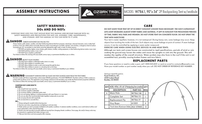
Ozark Trail W784.1 Assembly instructions and owner's manual

SlingFin
SlingFin CrossBow 2 instructions
Coleman
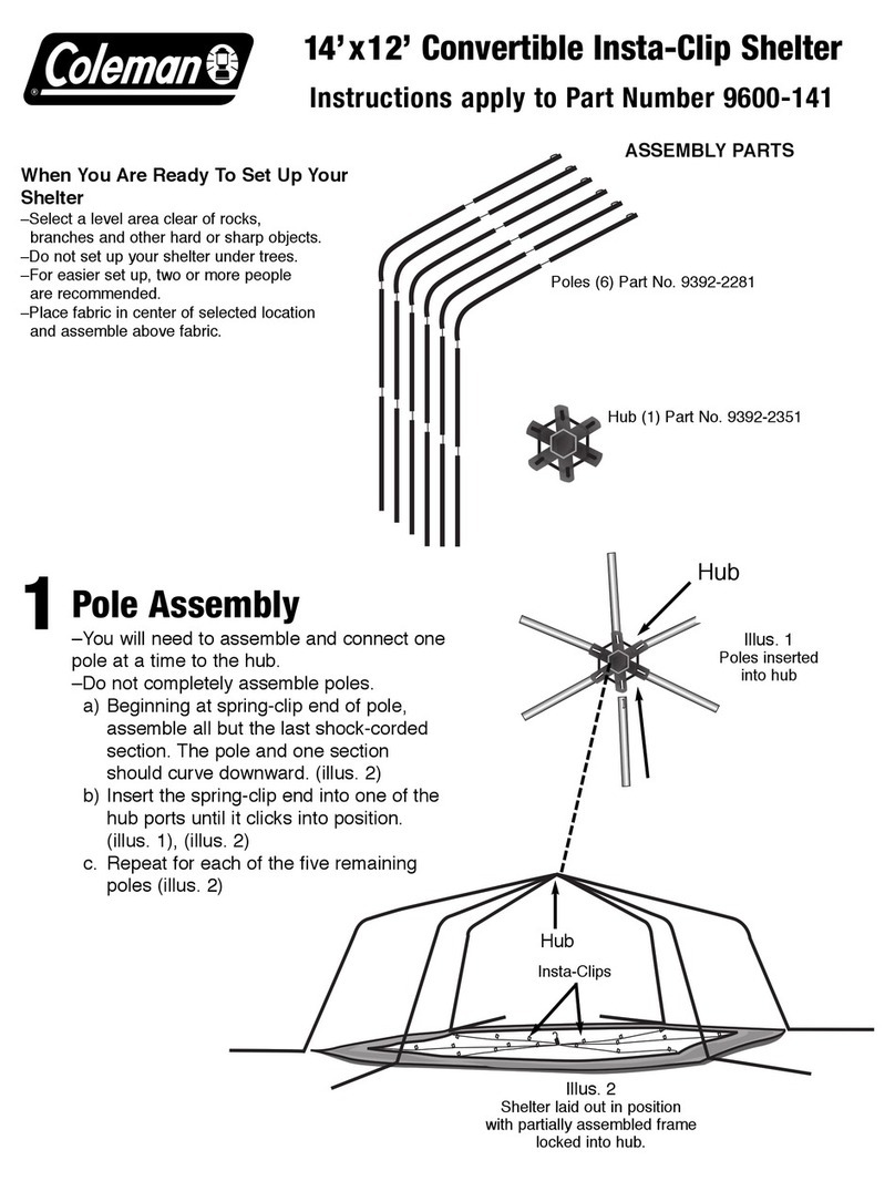
Coleman 9600-141 instructions
Palram
Palram Arizona 5000 Wave - WINGS manual
COVERPRO
COVERPRO 56184 Owner's manual & safety instructions
