Bastian Solutions Shoe Sorter Manual

Installation and Maintenance Manual
Model: Shoe Sorter
Effective October 2019
Rev. A1
Installation and Maintenance Manual: Shoe Sorter
_____________________________________________________________________________________________
Installation and Mai ntenance Man ual: Shoe S orter
Published October 2019
Rev.A1
2
Contributions
Revisions
ROLE
NAME
TITLE
Author
Ben Baker
Senior Design Engineer
Checker
Sam Osterhout
Project Engineer
Approver
Chris Perry
Engineering Manager
DATE
REVISION
REVISION DESCRIPTION
AUTHOR
10/21/2019
A1
Initial document creation
Ben Baker
Installation and Maintenance Manual: Shoe Sorter
_____________________________________________________________________________________________
Installation and Mai ntenance Man ual: Shoe S orter
Published October 2019
Rev.A1
3
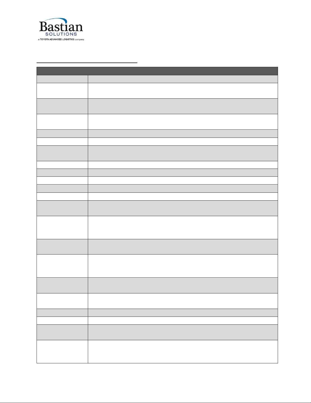
Term and Acronym Definitions
TERM/ACRONYM
DEFINITION
AC
Alternating current
Accumulation
The collection or staging of multiple cartons, cases, or totes of product on conveyor.
Back pressure
Pressure against carton(s) in the direction of carton flow resulting from weight of densely
accumulated cartons.
BF
Between frame; this refers to the distance between conveyor bed side frames.
BHCS
Button head cap screw
BOM
Bill of Materials
BRBDC
Belted Roller Bed Direct Current; DC roller conveyor format driven by brushless DC servo
motors.
Carton or Case
Term for conveyable items generally contained in cardboard boxes.
CB
Carriage bolt
CCW
Counter-clockwise
CW
Clockwise
DC
Direct current
DC Card
A control card used to power and control the logic used when operating a MDR in DC
conveyor applications.
Diffuse
A photoeye format that houses both the emitter and receiver and senses an object when
the light beam is reflected back to the sensor. This type of photoeye is a standalone unit
and does not use reflectors.
Discharge
The point where cartons, cases, or totes exit a conveyor or similar unit used in a material
handling system.
Divert
(noun) A conveyor unit used to change the direction of a carton, case, or tote in a
controlled manner. (verb) To change the direction of a carton, case, or tote in a
controlled manner.
Drive Pulley
A motor-driven pulley used to transmit rotational energy to linear motion in AC belts.
E-stop
A highly visible button or pull cable designed to shut down equipment in the case of an
emergency.
ETO
Engineered to Order; Orders requiring custom Engineering
FAT
Factory Acceptance Testing
Flange
A feature in sheet metal consisting of a face and bend connected to an existing face
along a straight edge.
Gapping
The separation of cartons, cases, or totes which are initially in contact with one another.
Generally done by progressively increasing the speed of consecutive zones, forcing
cartons, cases, or totes to "pull a gap."
Installation and Maintenance Manual: Shoe Sorter
_____________________________________________________________________________________________
Installation and Mai ntenance Man ual: Shoe S orter
Published October 2019
Rev.A1
4
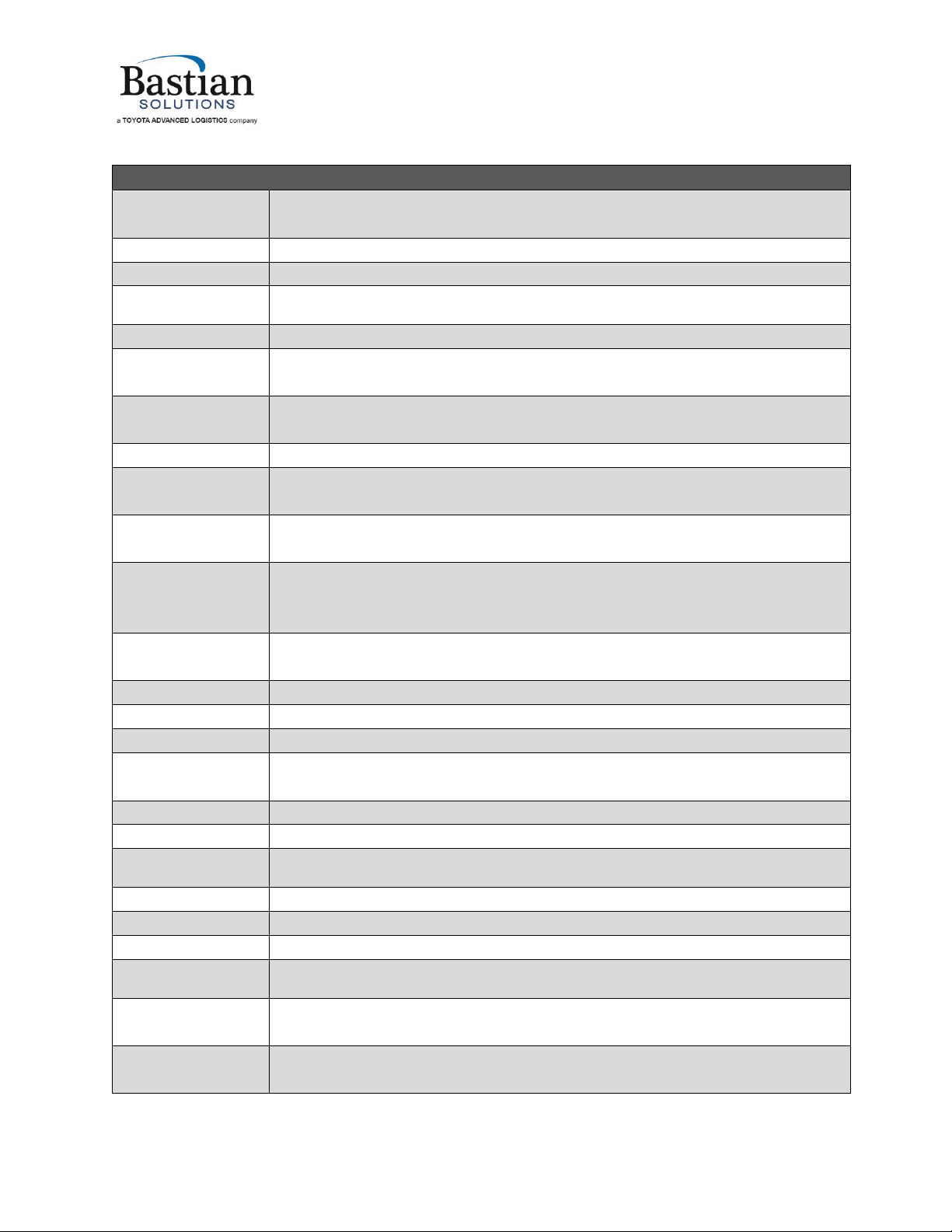
TERM/ACRONYM
DEFINITION
Guide Rail
Mechanism used to maintain the desired position of conveyable cartons, cases, or totes
on their respective conveying surface.
HHCS
Hex head cap screw
HMI
Human-Machine Interface; an operating console or control panel of a conveyor system.
HTL
High Threshold Logic. In the context of an encoder, a differential push-pull output
intended to operate on 24VDC.
ID
Inner diameter of a circular, cylindrical or arced body.
Idler Roller
Cylindrically-shaped material handling component that is unpowered and used to
support a belt.
Infeed
The point where cartons, cases, or totes enter a conveyor or similar unit used in a
material handling system.
LOTO
Lockout Tagout
Mark Number
A numeric or alphanumeric term used to uniquely identify a conveyor bed or collection
of beds (of similar model type) within a material handling system.
Match
A mark made on mating conveyor assemblies to assist in identifying orientation and
placement within a system.
MDR
Motorized drive roller; DC powered conveyor roller with an internally mounted motor
which may be controlled via internal or external commutation.
MSD
Master specification document; a document used to describe a product's intended
capabilities, appearance, and interaction with users.
NO
Normally Open
OAW
Overall width of any given conveyor bed.
OD
Outer diameter of a circular, cylindrical, or arced body.
O-Ring
A plastic ring with a circular cross section used for power transmission in DC conveyor
applications.
OSHA
Occupational Safety and Health Administration
OTD
On-Time Delivery
Photoeye
Device used to detect the presence of an object-such as a carton, case, or tote-by use of
an emitter and receiver (not necessarily in the same unit as one another).
PM
Project Management (or Project Manager)
PO
Purchase Order
PPE
Personal protective equipment
Proximity Sensor
(“Prox”)
A sensor able to detect the presence of nearby objects without any physical contact.
Typically an inductive sensor that detects nearby electrically conductive (metal) objects.
Pulley
Mechanical device used to change the direction of the belt in a conveyor system, to drive
and/or tension the belt.
Reflector
A reflective component needed for retroreflective photoeyes to receive transmitted light
or radiation when no object is in front of the photoeye.
Installation and Maintenance Manual: Shoe Sorter
_____________________________________________________________________________________________
Installation and Mai ntenance Man ual: Shoe S orter
Published October 2019
Rev.A1
5
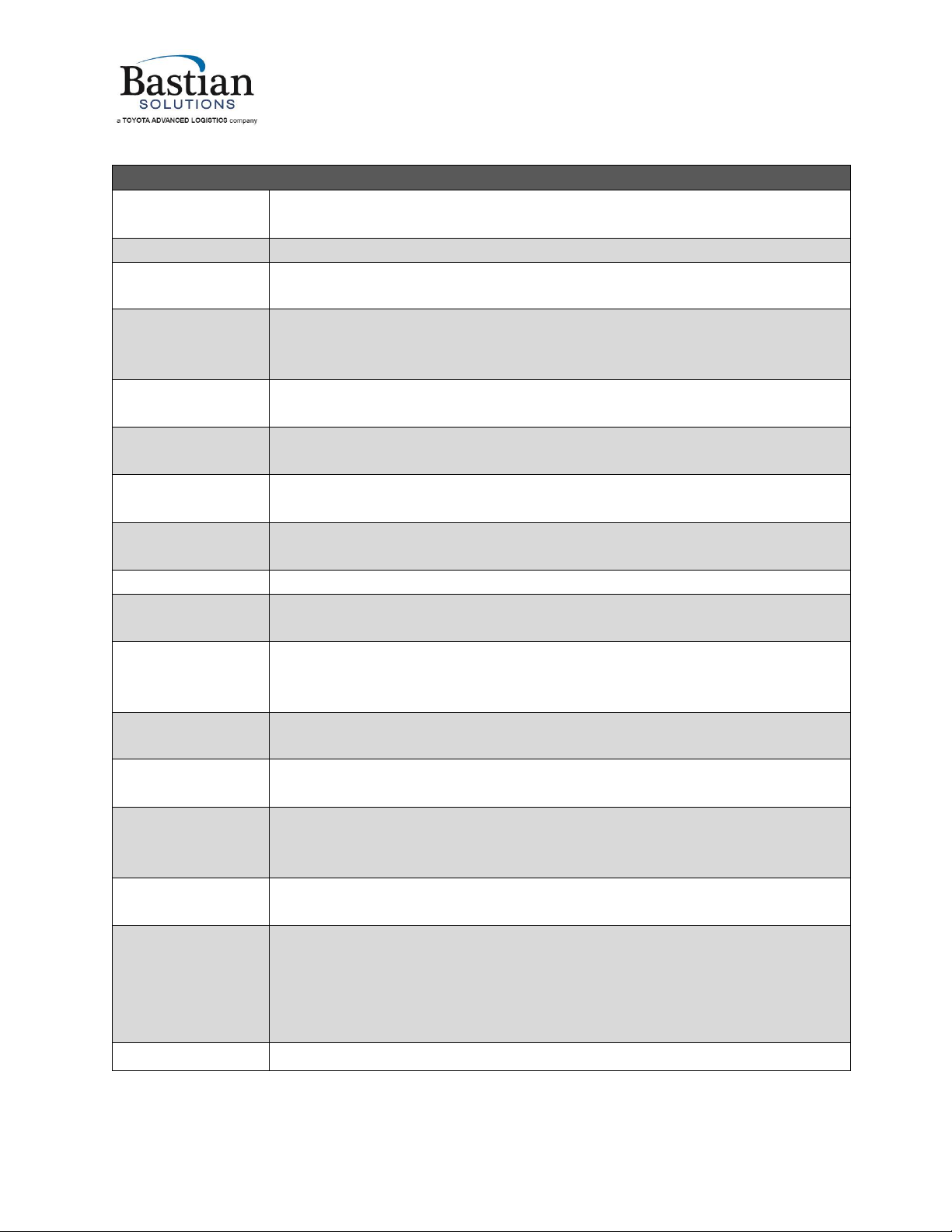
TERM/ACRONYM
DEFINITION
Retroreflective
Of or relating to a surface or device that reflects light or other radiation back to its
source.
Return Idlers
Belt-routing rollers on the underside of any given AC conveyor.
RLSDC
Roller Live Spur Direct Current; DC roller conveyor powered by live MDRs and configured
as a spur.
Roller
Powered or unpowered cylindrically-shaped material handling component used for
mechanical power transmission, a conveying surface, and/or support for a belted
conveying surface.
Shingling
Event in which surfaces of adjacent cartons, cases, or totes are forced to lift off the
conveyor due to elevated uneven carton, case, or tote back pressure.
Shoe
A sliding element that engages with cartons, cases, or totes to divert from a shoe sorter
onto a spur.
Side Cover
A PVC cover used to conceal and protect electrical components and wiring from foreign
debris and moving obstacles.
Side Frame
Structural member used to support rotating components needed for conveyor beds.
Singulation
The active separation of cartons, cases, or totes.
Skatewheel
Small unpowered wheels used to replicate nearly frictionless guidance or support of
conveyable cartons, cases, or totes.
Skew
A format of DC conveyor where one end of all rollers are shifted one roller position to
provide an angled conveying surface for left or right justification of cartons, cases, or
totes.
SKU
Stock Keeping Unit; Product and service identification code for a product (i.e. bar code).
Slug
Collection of two or more cartons, cases, or totes that are in contact with one another.
Snub Roller
A roller or pulley mounted to increase the arc of contact between a belt and drive pulley.
Additionally, this can be used to change the direction of the return belt travel.
Sorter
Any piece of conveyance equipment used to divert a series of cartons, cases, or totes
simultaneously.
Splice Assembly
A five-component assembly-consisting of a plate (or formed plate), two bolts, and two
nuts-that is used to secure a piece of guide rail to an adjacent piece of guide rail, or a
side frame to an adjacent side frame. This is used to provide additional structural rigidity
and ensure relative position of components is maintained.
SPST
Single Pole Single Throw; a type of electrical switch.

Installation and Maintenance Manual: Shoe Sorter
_____________________________________________________________________________________________
Installation and Mai ntenance Man ual: Shoe S orter
Published October 2019
Rev.A1
6
TERM/ACRONYM
DEFINITION
Spur
A format of DC conveyor used to create linear transitions into intersecting lines of
conveyor positioned at a non-perpendicular angle. Typically includes 30deg and 22deg
configurations.
Tail Pulley
A non-driven pulley located at the tail end of the conveyor.
Takeup Pulley
Pulley with an adjustable position used to eliminate unnecessary slack in a belt.
Takeup Screws
Adjustment screw used to adjust the position of a takeup pulley.
TOCS
Top of Conveying Surface; this refers to the elevation of the conveying surface with
respect to the floor on which the conveyor is sitting. Interchangeable with TOR but
applicable to non-roller conveyors as well.
TOR
Top of roller; this refers to the elevation of the conveying surface with respect to the
floor on which the conveyor is sitting.
Track
To adjust the position of conveyor components in such a way that engourages proper
belt alignment on a system.
Tracking Bands
Thin plastic bands installed on head or secondary drive roller to help keep DC format
conveyor belts tracked.
UHMW
Ultra-high molecular weight polyethylene
VFD
Variable Frequency Drive. An electronic variable-speed control for an AC induction
motor.
Waterfall
Method of overlapping guide rail such that cartons, cases, or totes cannot catch on
downstream guide rail.
Wiz Nut
A serrated flange nut used to cut into the surface of the component it is tightened
against.

Installation and Maintenance Manual: Shoe Sorter
_____________________________________________________________________________________________
Installation and Mai ntenance Man ual: Shoe S orter
Published October 2019
Rev.A1
7
Table of Contents
1Introduction ................................................................................................................. 11
2OSHA And Safety.......................................................................................................... 11
3Model: Shoe Sorter....................................................................................................... 11
4Receiving...................................................................................................................... 12
4.1 Mark Numbers..................................................................................................................12
4.2 Skid Contents....................................................................................................................13
4.3 Skid Documentation..........................................................................................................13
5Installation................................................................................................................... 14
5.1 Mechanical Installation .....................................................................................................14
5.1.1 Bed Section Placement ..........................................................................................................................14
5.1.2 Floor Support Installation ......................................................................................................................14
5.1.3 Section Fastening and Rail Alignment....................................................................................................15
5.1.4 Spur Installation.....................................................................................................................................17
5.1.5 Chain Installation ...................................................................................................................................19
5.1.6 Slat Installation ......................................................................................................................................21
5.1.7 Initial Startup Procedure........................................................................................................................23
5.1.8 Setting Infeed Conveyor ........................................................................................................................23
5.1.9 Setting Discharge Conveyor...................................................................................................................27
5.1.10 Installing Guards and Guiderail..............................................................................................................28
5.1.11 Installing Side Covers .............................................................................................................................29
5.1.12 Setting Oiler Flow...................................................................................................................................30
5.2 Electrical Installation.........................................................................................................32
5.2.1 Drive Motor Settings..............................................................................................................................32
5.2.2 Components requiring 3 phase AC power connections.........................................................................33
5.2.3 Components requiring 24VDC power connections................................................................................33
5.2.4 Components requiring 48VDC power connections................................................................................34
5.2.5 List of Sensors (discrete)........................................................................................................................34
5.2.6 Communication between system PLC and divert control box...............................................................36
6Operation..................................................................................................................... 38
6.1 Startup Procedure.............................................................................................................38
6.2 Troubleshooting Faults......................................................................................................39
7Maintenance ................................................................................................................ 40
7.1 Slat and shoe repair, replacement, and service ..................................................................40
7.2 Divert switch repair, replacement, and service...................................................................41
7.3 Chain Adjustment..............................................................................................................41
7.4 Recommended Preventative Maintenance Schedule..........................................................42
Appendix 1 Section Weights........................................................................................... 44
Appendix 2 Oiler System Recommended Flow Rates and Lubrication Intervals ............... 46
Appendix 3 General Arrangement Drawings................................................................... 47
Appendix 4 Electrical Schematics for Divert Control Box................................................. 70

Installation and Maintenance Manual: Shoe Sorter
_____________________________________________________________________________________________
Installation and Mai ntenance Man ual: Shoe S orter
Published October 2019
Rev.A1
8
List of Figures
Figure 1-Shoe Sorter Section Types and General Arrangement.................................................................11
Figure 2-Mark Number Stickers..................................................................................................................12
Figure 3-Skid Sticker....................................................................................................................................13
Figure 4-Floor Support Installation Detail ..................................................................................................15
Figure 5-Bed Section Fastening Detail ........................................................................................................16
Figure 6-Typical Spur Positioning................................................................................................................18
Figure 7-Spur Mounting Detail....................................................................................................................18
Figure 8-Chain Connection Detail ...............................................................................................................19
Figure 9-Slat Installation Detail...................................................................................................................21
Figure 10-Spring Clip Seating Detail............................................................................................................22
Figure 11-Knife Edge Installation Positioning .............................................................................................24
Figure 12-Knife Edge Nosebar Positioning Detail .......................................................................................25
Figure 13-Side View of Knife Edge Conveyor..............................................................................................26
Figure 14-Belt Tracking by Adjusting Snub Rollers .....................................................................................27
Figure 15-Discharge Transition Assembly Positioning Detail......................................................................28
Figure 16-Chain Guard, Guiderail, and Side Cover Installation...................................................................29
Figure 17-Oiler Pump and Flow Adjustment Panel.....................................................................................32
Figure 18-General Arrangement, Shoe Sorter Slat and Chain Exploded View, Sheet 1 of 1 ......................47
Figure 19-General Arrangement, Shoe Sorter Divert Section, Sheet 1 of 2 ...............................................48
Figure 20-General Arrangement, Shoe Sorter Divert Section, Sheet 2 of 2 ...............................................49
Figure 21-General Arrangement, Shoe Sorter Divert Switch, Sheet 1 of 3.................................................51
Figure 22-General Arrangement, Shoe Sorter Divert Switch, Sheet 2 of 3.................................................52
Figure 23-General Arrangement, Shoe Sorter Divert Switch, Sheet 3 of 3.................................................53
Figure 24-General Arrangement, Shoe Sorter Divert Receiver and Shoe Return, Sheet 1 of 1 .................54
Figure 25-General Arrangement, Shoe Sorter Tail, Sheet 1 of 2 ................................................................55
Figure 26-General Arrangement, Shoe Sorter Tail, Sheet 2 of 2 ................................................................56
Figure 27-General Arrangement, Shoe Sorter Drive, Sheet 1 of 2 .............................................................57
Figure 28-General Arrangement, Shoe Sorter Drive, Sheet 2 of 2 .............................................................58
Figure 29-General Arrangement, Shoe Sorter Discharge Transition, Sheet 1 of 1.....................................60
Figure 30-General Arrangement, Shoe Sorter Oiler, Sheet 1 of 1 ..............................................................62
Figure 31-General Arrangement, Shoe Sorter Chain Guide Fastening Detail, Sheet 1 of 1........................63
Figure 32-General Arrangement, Shoe Sorter Debris Sensor Detail, Sheet 1 of 1 .....................................64
Figure 33-General Arrangement, Shoe Sorter Knife Edge, Sheet 1 of 2.....................................................66
Figure 34-General Arrangement, Shoe Sorter Knife Edge, Sheet 2 of 2.....................................................67
Figure 35-General Arrangement, Shoe Sorter Induction Gapper, Sheet 1 of 1..........................................69
Figure 36-Electrical Schematic for Divert Control Box, Sheet 1 of 7...........................................................70
Figure 37-Electrical Schematic for Divert Control Box, Sheet 2 of 7...........................................................71
Figure 38-Electrical Schematic for Divert Control Box, Sheet 3 of 7...........................................................72
Figure 39-Electrical Schematic for Divert Control Box, Sheet 4 of 7...........................................................73
Figure 40-Electrical Schematic for Divert Control Box, Sheet 5 of 7...........................................................74
Installation and Maintenance Manual: Shoe Sorter
_____________________________________________________________________________________________
Installation and Mai ntenance Man ual: Shoe S orter
Published October 2019
Rev.A1
9
Figure 41-Electrical Schematic for Divert Control Box, Sheet 6 of 7...........................................................75
Figure 42-Electrical Schematic for Divert Control Box, Sheet 7 of 7...........................................................76
List of Tables
Table 1-List of Sensors ................................................................................................................................34
Table 2-Divert Box I/O Mapping .................................................................................................................37
Table 3-Recommended Preventative Maintenance Schedule ...................................................................42
Table 4-List of Section Weights...................................................................................................................44
Table 5-List of Drive Motor Weights...........................................................................................................45
Table 6-Oiler Pump Runtime (in seconds) Per Lubrication Interval............................................................46
Table 7-Recommended Lubricant Flow Rates and Lubrication Intervals ...................................................46
Table 8-BOM for GA-SHOE-36-120-0001....................................................................................................50
Table 9-BOM for GA-SHOE-MW-88-0001...................................................................................................59
Table 10-BOM for GA-SHOE-MW-88-0002.................................................................................................61
Table 11-BOM for GA-SHOE-MW-120-0002...............................................................................................65
Table 12-BOM for GA-SHOE-MW-48-0001.................................................................................................68
Reference Documents
MANUFACTURER
DOCUMENT TITLE
DOCUMENT
NUMBER
URL
Teknic, Inc.
ClearPath MC/SD User
Manual Rev.3.05
N/A
https://www.teknic.com/files/downloa
ds/clearpath_user_manual.pdf
Teknic, Inc.
AC ClearPath-MC/SD User
Manual Rev.3.06
N/A
https://www.teknic.com/files/downloa
ds/ac_clearpath-mc-sd_manual.pdf
The Diamond
Chain Company
Diamond Chain
Maintenance Guide
11255_201903
https://www.diamondchain.com/wp-
content/uploads/2017/03/
catalogs/maintenance-guide/
maintenance-guide.pdf
The Diamond
Chain Company
Diamond Series Product
Catalog
DC1000-201905
https://www.diamondchain.com/wp-
content/uploads/2018/01/2019_
Diamond_Chain_Catalog_links.PDF
The Diamond
Chain Company
Roller Chain Wear Gauge
Instructions
DCWG-2013
N/A
ABB Motors and
Mechanical, Inc.
(formerly Baldor
Electric
Company)
Instruction Manual for
DODGE® Setscrew,
Eccentric Collar, D-Lok, H-E
Series, E-Z Kleen, Ultra
Kleen and Food Safe
Mounted Ball Bearings
MN3016
https://www.baldor.com/mvc/
DownloadCenter/Files/MN3016
ifm Efector, Inc.
Operating instructions
Retro-reflective sensor
(OGP7xx)
80284283 / 00
https://www.ifm.com/mounting/
80284283UK.pdf
Installation and Maintenance Manual: Shoe Sorter
_____________________________________________________________________________________________
Installation and Mai ntenance Man ual: Shoe S orter
Published October 2019
Rev.A1
10
MANUFACTURER
DOCUMENT TITLE
DOCUMENT
NUMBER
URL
Insight
Automation
EZ24 Family Reference
Manual
PR-1100
https://www.pulseroller.com/files/NA/
Control%20Literature%20&%20
Drawings/EZ-24/Users%20Manual%20
and%20Specifications/Users_Guide.pdf
SEW Eurodrive
Operating Instructions (AC
Motors DR..71-315, DRN63-
315, DR2..63-80)
24745332/EN
https://download.sew-eurodrive.com/
download/pdf/24745332.pdf
SEW Eurodrive
Assembly and Operating
Instructions (Gear unit
series R..7, F..7, K..7, K..9,
S..7, SPIROPLAN® W)
21932786/EN
https://download.sew-eurodrive.com/
download/pdf/21932786.pdf
Bijur Delimon
International
SureFire II Lubricator
Automatic, Oil & Fluid
Grease, Single Phase
36410
http://www.bijurdelimon.com/
fileadmin/products/docs/bdius/
Datasheets/36410_LUB_SureFire-II-PDI-
SLR_DS-R2.pdf
Bijur Delimon
International
Operators Manual
Controller,SureFire II (Single
Phase PDI - SLR(24VDC,
115VAC & 230VAC))
36412
http://www.bijurdelimon.com/
fileadmin/bdide/downloads/36412_
SureFire-II_Controller_OM_2017_
1_GB.pdf
Bijur Delimon
International
SureFire II Lubricator Quick
Start Manual
71070
http://www.bijurdelimon.com/
fileadmin/products/docs/bdius/
Operator-Manuals/71070_SureFire-II-
Quick_Start_QS-R3.pdf

Installation and Maintenance Manual: Shoe Sorter
_____________________________________________________________________________________________
Installation and Mai ntenance Man ual: Shoe S orter
Published October 2019
Rev.A1
11
1Introduction
Thank you for choosing ZiPline Conveyor. The following manual serves as a guide for installation, part
replacement, and general maintenance for your material handling equipment. It is important to read the
manual and follow any instructions as it provides important safety information for personnel and will
maximize the longevity of the conveyor.
The information contained in this manual applies only to the products described. Uses, activities, or
processes related to installing or maintaining the equipment that are not explicitly described in this
manual are considered out of scope. Please contact Bastian Solutions ZiPline Conveyors for any
questions or support that is not clearly addressed in this document. ZiPline Conveyor is not responsible
for misuse of the equipment described in this manual or misuse of information in this manual. If you
have any questions, contact ZiPline Conveyor Customer Service or Support at
ZiPlineSupport@BastianSolutions.com.
2OSHA And Safety
ZiPline Conveyor is not responsible for ensuring that conveyors used in a system abide by OSHA
standards. Safety is of primary importance to our company, but as a product distributor we ask that
system integrators and end users conform with all applicable OSHA standards. We encourage that all
warnings in this manual are followed to avoid unnecessary risk.
3Model: Shoe Sorter
The ZiPline Shoe Sorter is a slat conveyor with movable shoes that slide laterally on the slats when
diverted by rails below the conveying surface. The shoe sorter is used for high-speed, high-volume
primary sortation, and is optimized for conveyance of cartons and totes.
Figure 1-Shoe Sorter Section Types and General Arrangement
Figure 1 shows a side view of an example shoe sorter. Product flows over an induction conveyor,
containing at least a knife edge transition belt, but commonly also containing one or more gapper
conveyors to set correct product spacing. The product then flows across the sorter, which contains one
or more divert sections. Each divert section will mate to a spur and a takeaway conveyor line. Products
that do not get diverted will continue down the length of the sorter onto discharge conveyor.

Installation and Maintenance Manual: Shoe Sorter
_____________________________________________________________________________________________
Installation and Mai ntenance Man ual: Shoe S orter
Published October 2019
Rev.A1
12
4Receiving
Upon delivery of any ZiPline Conveyor, please review and check the following:
•The quantity of items received against the Bill of Lading.
•Complete a visual inspection of equipment to determine any damage that may have occurred
during shipping. If damage is present, document with pictures.
•Review Mark Number information and layout locations. More information can be found in
subsection 4.1.
If there are any missing or damaged components contact your ZiPline Conveyor representative with as
much detail as possible. If you are unsure of your ZiPline Conveyor representative, please contact
Customer Service at ZiPlineSupport@BastianSolutions.com.
4.1 Mark Numbers
A mark number is a specific number given to a piece of equipment. A mark number is usually made up of
a single product line (RZPDC, RLVDC, BZPDC, etc.) but can contain many bed section lengths. They can
range from two inches to hundreds of feet in length. The mark number is used to help identify where
the piece of equipment will go within the system layout.
Every bed section of conveyor will have (2) stickers. One sticker on the infeed end of the bed, and one
sticker on the discharge end of the bed. Each sticker will contain the following information:
•ZiPline Project Number and Name
•Model Type
•Mark Number
•Match
•Piece
•Flow
Figure 2 shows the stickers that would appear on an RZPDC that has two bed sections.
•The Match field on the stickers is used to indicate if two bed sections are to be spliced to one
another.
•As shown in Figure 2 the stickers where the two beds splice together both contain Match: 1.
•The Piece field defines the bed section number within the mark.
•The flow refers to the direction of product flow along the conveyor system.
Figure 2-Mark Number Stickers

Installation and Maintenance Manual: Shoe Sorter
_____________________________________________________________________________________________
Installation and Mai ntenance Man ual: Shoe S orter
Published October 2019
Rev.A1
13
4.2 Skid Contents
Skids will contain varying combinations of conveyor sections, support structures, accessories, and
pertinent hardware. For protection of product integrity during shipping, accessories and supports may
be delivered on separate, but labeled skids.
4.3 Skid Documentation
All shipments will contain a Bill of Lading for the delivery company, a skid label, and a skid
manifest. Skid labels have the contents of each shipped item located on the skid. Figure 3 shows
a sample of a skid label. These stickers are placed on the surface of each skid.
Figure 3-Skid Sticker

Installation and Maintenance Manual: Shoe Sorter
_____________________________________________________________________________________________
Installation and Mai ntenance Man ual: Shoe S orter
Published October 2019
Rev.A1
14
5Installation
Ensure that your conveyor equipment has been securely fastened to the floor or other mounting surface
before full operation occurs.
Consideration should be given to floor point loading prior to installation to ensure
proper support of equipment. See Appendix 1 for section weights.
5.1 Mechanical Installation
5.1.1 Bed Section Placement
1. Lay out chalk lines on floor for placement –See the system layout/installation drawings.
2. Lift the drive section off the skid using the provided lifting eyes on the frame
3. Set the drive section in position. Refer to the system layout/installation drawing and Figure 1.
DO NOT pick up or move drive section using the lifting eyes on the motor or
gearbox. Damage to the gearbox or drive shaft may result.
On larger units, the motor may be shipped separate from the drive unit. See SEW
Eurodrive Gear Unit Assembly and Operating Instructions section 4 for installation
instructions.
Secure the drive unit to the floor before installing the motor. Heavy gearmotors
may cause the drive unit to become unbalanced or tip during installation.
4. Adjust the foot bolts on the drive so all four feet are in contact with the floor and the drive section is
level and aligned to the chalk lines.
5. Check that the height of the drive section matches the specified height on the system layout
drawing (the top of the frame is 3/8” below the final slat surface)
6. If the drive section is out of square, use the provided tension rod for squaring adjustment
7. Set each section and bolt them together, working backwards from the drive to the tail. See Figure 5
for details on fastening the sections together. Hand tighten only at this stage.
8. Check square on each section and check the straightness of the sorter before securing to the floor.
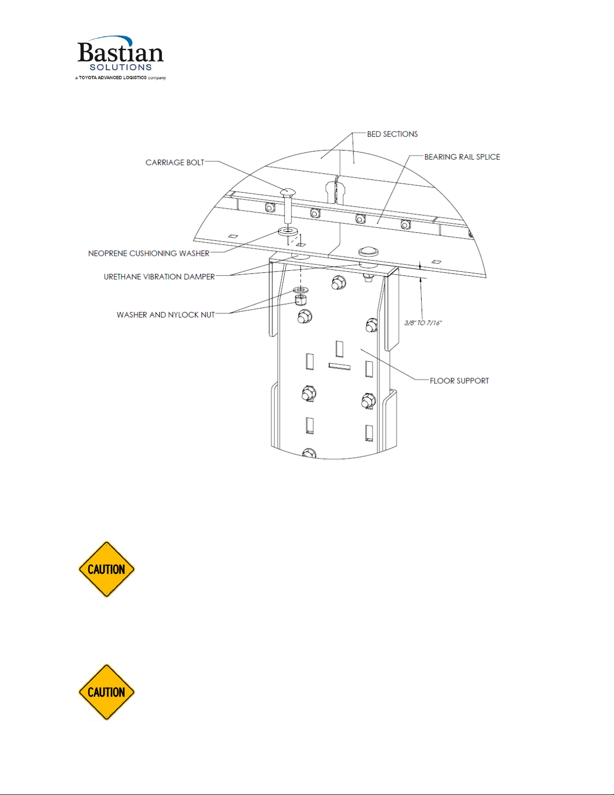
5.1.2 Floor Support Installation
1. See Figure 4
2. Place a thin black neoprene washer between the bolt head and the flange of the sideframe.
3. Place a green urethane vibration damper between the sideframe and the floor support.
Installation and Maintenance Manual: Shoe Sorter
_____________________________________________________________________________________________
Installation and Mai ntenance Man ual: Shoe S orter
Published October 2019
Rev.A1
15
Figure 4-Floor Support Installation Detail
4. Adjust the urethane vibration damper to 3/8” to 7/16” tall (1/8” to 1/16” compression).
5. Adjust the top of conveying surface height by adjusting the floor support.
Do not use vibration dampers for height adjustment. Excessive compression can
damage the vibration dampers and will increase vibrations transmitted into the
floor supports.
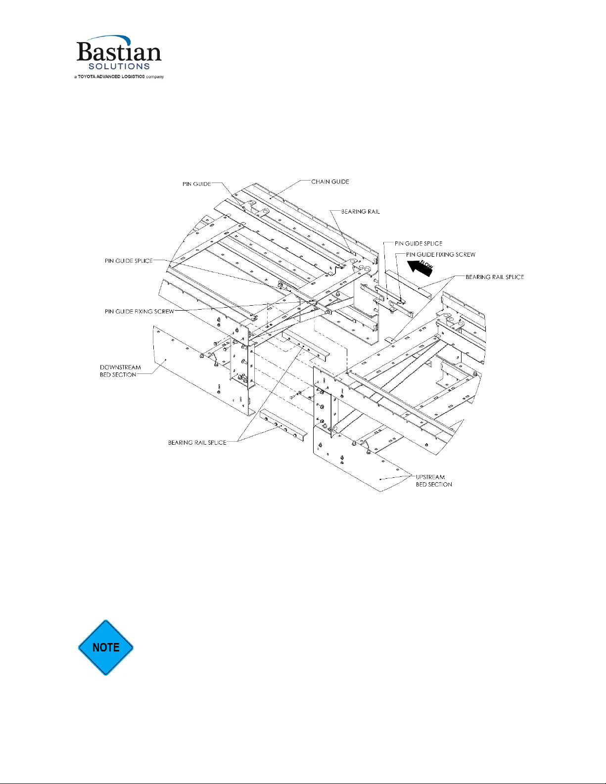
5.1.3 Section Fastening and Rail Alignment
1. See Figure 5 for details on fastening sections together.
2. Use of a laser level is recommended to set the sorter straight and level.
The sorter must be level front-to-back, side-to side, and all sections must be aligned
straight to within the tolerances specified in step 3. Misalignment can cause noisy
operation and/or damage to the chain, bearings, and slats.
Installation and Maintenance Manual: Shoe Sorter
_____________________________________________________________________________________________
Installation and Mai ntenance Man ual: Shoe S orter
Published October 2019
Rev.A1
16
3. Lateral straightness tolerances must be within +/- 1/2 inch per 100 feet. Check each bed section
joint to ensure there are no bumps or discontinuities (use a laser to sight from the drive to the tail).
4. Ensure the drive and tail shafts are level by placing a precision level directly on the respective shafts.
See Diamond Chain Maintenance Guide section 1 for chain alignment tolerances.
Figure 5-Bed Section Fastening Detail
5. Place a straightedge across the gap in the bearing rail between each bed section, and install the
bearing rail splice so that it mates with the installed bearing rail on both the upstream and
downstream ends.
a. If there are any bumps created by misalignment where the bearing rail ends meet, it will cause
excessive noise during operation and, if the misalignment is severe, can damage the chain
mount bearings over time.
The bearing rail splice can also be used for pulling sections together (aligning) left-to-
right. Ensure the section splice bolts are loose enough to allow movement before
pulling the sections together.
Installation and Maintenance Manual: Shoe Sorter
_____________________________________________________________________________________________
Installation and Mai ntenance Man ual: Shoe S orter
Published October 2019
Rev.A1
17
6. Place a straightedge across the gap in the pin guide between bed sections, and install the pin guide
splice so that it mates with the installed pin guide on both the upstream and downstream ends. The
pin guide and pin guide splices should be approximately centered in their mounting slots.
a. If there are any bumps created by misalignment where the pin guide ends meet, it will cause
excessive noise during operation and, if the misalignment is severe, can damage the pin guide
covers and the slat mounts over time.
The pin guide fixing screw is always on the upstream end with respect to chain flow.
It is important to maintain this orientation, or the plastic cover could come off and
cause damage.
7. Once the sections are straight and level, fully tighten all section splice bolts and secure to the floor
or decking.
a. Tighten 1/4”-20 fasteners to 8.4 ft-lb.
b. Tighten 3/8”-16 fasteners to 31 ft-lb.
c. Fastening hardware to secure the floor supports to the floor or decking is not provided by
ZiPline. Consult the hardware manufacturer for appropriate torque values.
Ensure the securing method is appropriate for the application. Installations in seismic
zones will generally require an independent seismic review. ZiPline does not provide
general-purpose recommendations for concrete anchors or other fastening methods,
since fastening requirements depend on the site-specific details of the mounting
surface.
8. Verify straightness and level again once all sections are fully secured and all bolts are tightened.
Adjust the section positioning as needed if any sections have moved out of alignment.
5.1.4 Spur Installation
1. The spur mounting brackets share mounting bolts with the chain guards. Spur locations use a chain
guard piece painted standard silver color instead of safety yellow.
2. Attach the spurs to the sorter by bolting the spur to the slots in the mounting brackets using 3/8”
carriage bolts.
3. Spur locations are adjustable left-to-right using the provided slots.
4. Locate spurs per the system installation drawing. See Figure 6 for typical spur positioning. Spur
alignment is given relative to the divert rail and the positions of installed shoes.
5. Set spurs approximately 3/8” lower than the sorter TOCS using the spur jack bolts.
6. Tighten spur mounting bolts once spur is in its final position. See Figure 7.
a. Tighten 3/8”-16 fasteners to 31 ft-lb.
The provided adjustment travel is intended for optimizing the spur location relative to
the divert rail. Moving the spur a large distance may cause problems diverting large
packages, depending on the system layout.

Installation and Maintenance Manual: Shoe Sorter
_____________________________________________________________________________________________
Installation and Mai ntenance Man ual: Shoe S orter
Published October 2019
Rev.A1
18
Figure 6-Typical Spur Positioning
Figure 7-Spur Mounting Detail
2” APPROXIMATELY
1 3/8” APPROXIMATELY
Installation and Maintenance Manual: Shoe Sorter
_____________________________________________________________________________________________
Installation and Mai ntenance Man ual: Shoe S orter
Published October 2019
Rev.A1
19
5.1.5 Chain Installation
Run power to the main drive motor and verify the motor rotation direction before
installing the chain. Running the sorter backwards can cause damage to slats, chain, and
sorter internal components.
The “missing bearing”fork sensor on the first divert section is easy to damage when
installing the chain. This sensor is shipped separately for this reason; recommend
installing the sensor only after completing the chain installation.
1. The chain comes pre-assembled with chain mounts.
2. The chain is shipped and tagged in matched pairs (right and left)
a. Right and left sides of the sorter are determined by facing in the direction of product flow.
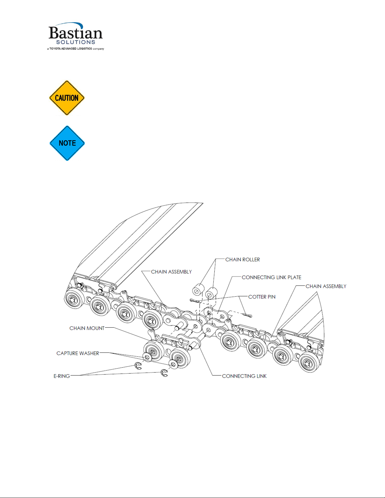
Figure 8-Chain Connection Detail
3. Always keep the matched pairs across from each other. Keep the tags on the chain until it is installed
in the sorter.
4. Lay out a matched pair of chain and hold it together with one slat approximately every two feet,
starting at the drive sprocket and working backwards.
Installation and Maintenance Manual: Shoe Sorter
_____________________________________________________________________________________________
Installation and Mai ntenance Man ual: Shoe S orter
Published October 2019
Rev.A1
20
a. See Section 5.1.6 for instructions on slat installation.
5. Join the chain sections with a connecting link, then install the chain mounts over the connecting link
section. See Figure 8.
6. Once the chain is installed on top of the sorter, use the drive sprocket to help pull the chain around.
7. Two options to turn the drive sprocket manually are:
a. The flat on the drive shaft (use a 1-1/8” open end wrench with a cheater bar or other long
handle extension)
b. Remove the fan cover and rotate the fan of the drive motor by hand (this method is slower, but
it requires lower torque due to the mechanical advantage of the gearbox)
The drive must be locked out during chain install—do not use the drive motor to
advance the chain during installation. Death or serious injury could result.
8. Attach ropes to the free end of the chain to help pull the chain through the catenary (force should
be transmitted through the drive sprocket; the ropes are to correctly guide the free end).
DO NOT pull on the slats or chain mounts. Damage to the slats or chain mounts could
result. Fasten any pulling devices (winches, come-alongs, etc.) directly to the chain,
with the use of a suitable spreader bar to ensure the force is exerted directly along
the length of the chain.
There will be, by design, one matched pair of chains that is a shorter length than the
others. This pair has been factory-cut to the appropriate length for the sorter
installation. As with all matched chain pairs, this pair must be kept directly across
from each other.
9. Install the short length chain pair last.
10. Depending on the sorter length and the chain weight, making the last chain splice may require the
use of come-alongs, ratchet straps, or other mechanical pulling devices to generate enough slack to
insert the last connector link.
11. Apply no more than 800 lbs of pulling force to each chain end (1600 lbs total).
12. If needed, adjust the position of the tail shaft (only if the chain cannot be assembled otherwise) to
gain extra slack. Ensure the tail shaft remains square to the sorter frame. See Figure 25 and Figure
26 in Appendix 3.
13. Once the chain installation is complete, install the “missing bearing”sensor on the first divert of the
sorter.
a. See Figure 21, Figure 22, and Figure 23 in Appendix 3 for drawings showing the mounting
details, location, and alignment of the pin sensor and “missing bearing” sensor.
b. The “missing bearing”sensor must be positioned 4-1/2” behind the pin sensor.
c. See Section 6.2 for detailed troubleshooting information on the “missing bearing”sensor.
Other manuals for Shoe Sorter
1
Table of contents
Other Bastian Solutions Industrial Equipment manuals


