Bastian Solutions BRBDC Manual

Installation and Maintenance Manual
Model: BRBDC
Effective October 2019
Rev.A1

Maintenance and Installation Manual: BRBDC
Published October 2019
Rev.A1
2
Contributions
ROLE
NAME
TITLE
Author
Brady Miller
Design Engineer
Checker
Raj Choudhuri
Design and Cost Engineer
Approver
Chris Perry
Engineering Manager
Revisions
DATE
REVISION
DESCRIPTION
AUTHOR
10/24/2019
A1
Initial Document Creation
Brady Miller

Maintenance and Installation Manual: BRBDC
Published October 2019
Rev.A1
3
Term and Acronym Definition List
TERM/ACRONYM
DEFINITION
BRBDC
Belted Roller Bed Direct Current; DC roller conveyor format driven by brushless DC
servo motor.
Carton or Case
Term for conveyable items generally contained in cardboard boxes.
CB
Carriage bolt.
DC
Direct current.
Discharge
The point where cartons, cases, or totes exit a conveyor or similar unit used in a
material handling system.
Guide Rail
Mechanism used to maintain the desired position of conveyable cartons, cases, or
totes on their respective conveying surface.
Idler Roller
Cylindrically-shaped material handling component that is unpowered and used to
support a belt.
Infeed
The point where cartons, cases, or totes enter a conveyor or similar unit used in a
material handling system.
Live
A zone of conveyor runs "live" when it runs whenever energized. It is for this
reason that live zones of conveyor do not have or need any photoeyes or
reflectors.
LOTO
Lockout Tagout.
Mark Number
A numeric or alphanumeric term used to uniquely identify a conveyor bed or
collection of beds (of similar model type) within a material handling system.
Match
A mark made on mating conveyor assemblies to assist in identifying orientation
and placement within a system.
OAW
Overall width of any given conveyor bed.
OSHA
Occupational Safety and Health Administration
Poly-V
A band or roller hub format with longitudinal ribs used for power transmission in
DC conveyor applications.
Roller
Powered or unpowered cylindrically-shaped material handling component used for
mechanical power transmission, a conveying surface, and/or support for a belted
conveying surface.
Side Cover
A PVC cover used to conceal and protect electrical components and wiring from
foreign debris and moving obstacles.
Side Frame
Structural member used to support rotating components needed for conveyor
beds.
TOR
Top of roller; this refers to the elevation of the conveying surface with respect to
the floor on which the conveyor is sitting.
Track
To adjust the position of conveyor components in such a way that encourages
proper belt alignment on a system.
Tracking Bands
Thin plastic bands installed on head or secondary drive roller to help keep DC
format conveyor belts tracked.
Wiz Nut
A serrated flange nut used to cut into the surface of the component it is tightened
against.

Maintenance and Installation Manual: BRBDC
Published October 2019
Rev.A1
4
Table of Contents
1Introduction ................................................................................................................... 6
2OSHA and Safety ............................................................................................................ 6
3Model: BRBDC................................................................................................................ 7
4Receiving........................................................................................................................ 8
4.1 Mark Numbers....................................................................................................................8
4.2 Skid Contents......................................................................................................................8
4.3 Skid Documentation............................................................................................................9
5Installation................................................................................................................... 10
6Maintenance and Operation......................................................................................... 11
6.1 Safety During Operation....................................................................................................11
6.2 Maintenance Schedule ......................................................................................................11
6.2.1 Mechanical Service ................................................................................................................................12
6.2.2 Electrical Service ....................................................................................................................................12
6.2.3 Replacing Idler Rollers ...........................................................................................................................12
6.2.4 Replacing Head Roller............................................................................................................................15
6.2.5 Replacing Motor ....................................................................................................................................16
6.2.6 Replacing Drive Band .............................................................................................................................18
6.2.7 Tracking Belt ..........................................................................................................................................19
6.2.8 Tracking Drive Band ...............................................................................................................................20
7Troubleshooting and Repair.......................................................................................... 20
8Standard Spare Parts .................................................................................................... 21
List of Figures
Figure 1: Exploded View of BRBDC ...............................................................................................................7
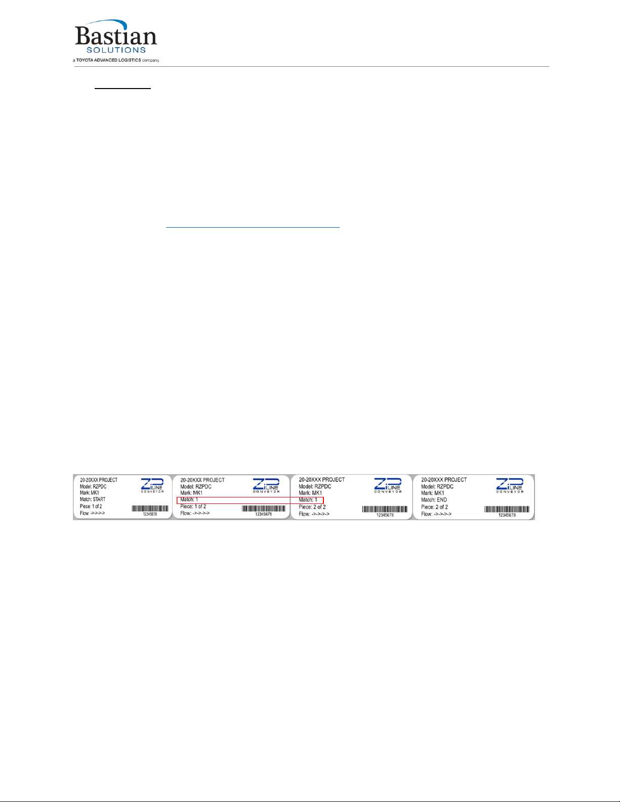
Figure 2: Mark Number Stickers ...................................................................................................................8
Figure 3: Skid Sticker.....................................................................................................................................9
Figure 4: Fastening BRBDC to Floor Support ..............................................................................................10
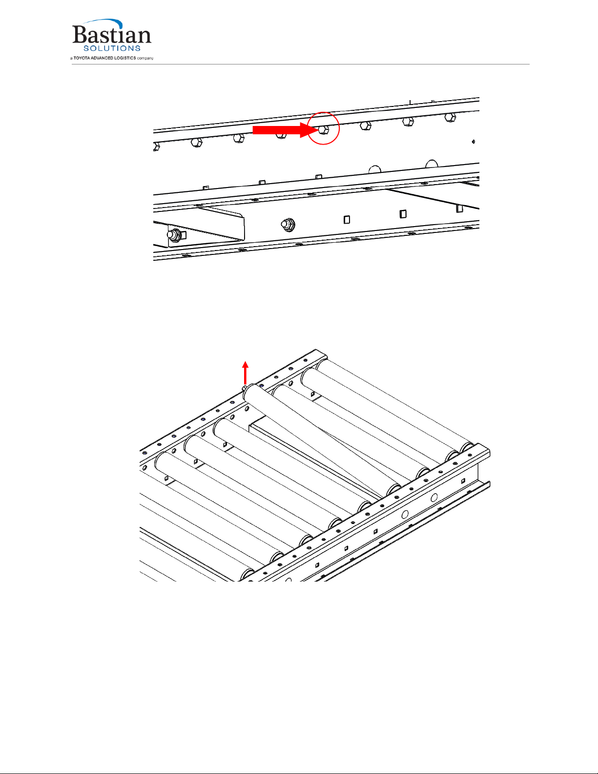
Figure 5: Roller Removal.............................................................................................................................13
Figure 6: Removing Roller from Side Frame, Belt Hidden for Visibility ......................................................13
Figure 7: Top View of BRBDC, Belt Hidden for Visibility .............................................................................14
Figure 8: Underside View of BRBDC............................................................................................................15
Figure 9: Exploded View of Motor Mounting Assembly.............................................................................16
Figure 10: Exploded View of Motor and Pulley Assembly ..........................................................................17
Figure 11: Band Guard Assembly................................................................................................................18
Figure 12: Top View of BRBDC ....................................................................................................................19
Figure 13: BRBDC Spare Parts Exploded View ............................................................................................21

Maintenance and Installation Manual: BRBDC
Published October 2019
Rev.A1
5
List of Tables
Table 1: Troubleshooting BRBDC ................................................................................................................20
Table 2: BRBDC Standard Spare Parts Table...............................................................................................21
Reference Documents
Manufacturer
Manual
Bastian Solutions
ZiPline Conveyor: Side Cover and Guiderail Installation Manual
Bastian Solutions
ZiPline Conveyor: Support Installation Manual
Bastian Solutions
ZiPline Conveyor: Teknic Motor Service Bulletin
Teknic, Inc.
MCVC-3441D Manual

Maintenance and Installation Manual: BRBDC
Published October 2019
Rev.A1
6
1Introduction
Thank you for choosing ZiPline Conveyor. The following manual serves as a guide for installation, part
replacement, and general maintenance for your material handling equipment. It is important to read the
manual and follow any instructions as it provides important safety information for personnel and will
maximize the longevity of the conveyor.
The information contained in this manual applies only to the products described. Uses, activities, or
processes related to installing or maintaining the equipment that are not explicitly described in this
manual are considered out of scope. Please contact Bastian Solutions ZiPline Conveyor for any questions
or support that is not clearly addressed in this document. ZiPline Conveyor is not responsible for misuse
of the equipment described in this manual or misuse of information in this manual. If you have any
questions, contact ZiPline Conveyor Customer Service or Support at
ZiPlineSupport@BastianSolutions.com.
2OSHA and Safety
ZiPline Conveyor is not responsible for ensuring that conveyors used in a system abide by OSHA
standards. Safety is of primary importance to our company, but as a product distributor we ask that
system integrators and end users conform with all applicable OSHA standards. We encourage that all
warnings in this manual are followed to avoid unnecessary risk.

Maintenance and Installation Manual: BRBDC
Published October 2019
Rev.A1
7
3Model: BRBDC
The Belted Roller Bed DC Conveyor (BRBDC) utilizes a belt that is driven by a DC motor to convey
product. The BRBDC conveyor is designed with a single head roller that pulls the belt in the direction of
flow while non-powered idler rollers support the belt throughout the length of the bed section. The
head roller is “live” meaning that it runs continuously whenever the Teknic motor is energized. The
model shown in Figure 1 serves as a reference to become familiar with the components and terminology
used in this manual. These terms will be used throughout the manual and are common among many of
the other ZiPline Conveyor product lines.
Figure 1: Exploded View of BRBDC
The model in Figure 1 is a BRBDC bed section. The BRBDC section has 4” roller centers and has (1) zone.
The zone is made up of carrying rollers, (1) Teknic motor and (1) head roller. The head roller is
connected to the Teknic motor by a Poly-V band while the carrying rollers are only in contact with the
belt. The conveyor runs continuously whenever energized.
TEKNIC MOTOR
HEAD ROLLER
SIDE FRAME
FLOW
BELT
DRIVE BAND

Maintenance and Installation Manual: BRBDC
Published October 2019
Rev.A1
8
4Receiving
Upon delivery of any ZiPline Conveyor, please review and check the following:
•The quantity of items received against the Bill of Lading.
•Complete a visual inspection of equipment to determine any damage that may have occurred
during shipping. If damage is present, document with pictures.
•Review Mark Number information and layout locations. More information can be found in
subsection 4.1.
If there are any missing or damaged components contact your ZiPline Conveyor representative with as
much detail as possible. If you are unsure of your ZiPline Conveyor representative, please contact
Customer Service at ZiPlineSupport@BastianSolutions.com.
4.1 Mark Numbers
A mark number is a specific number given to a piece of equipment. A mark number is usually made up of
a single product line (RZPDC, RLVDC, BZPDC, etc.) but can contain many bed section lengths. They can
range from two inches to hundreds of feet. The mark number is used to help identify where the piece of
equipment will go within the system layout.
Every bed section of conveyor will have (2) stickers. One sticker on the infeed end of the bed, and one
sticker on the discharge end of the bed. Each sticker will contain the following information:
•ZiPline Project Number and Name
•Model Type
•Mark Number
•Match
•Piece
•Flow
Figure 2 shows stickers that would appear on an RZPDC that has two bed sections.
Figure 2: Mark Number Stickers
The Match field on the stickers is used to indicate if two bed sections are to be spliced to one another.
As shown in Figure 2 he stickers where the two beds splice together both contain “Match: 1”.
The piece field defines the bed section number within the mark. The flow refers to the direction of
product flow along the conveyor system.
4.2 Skid Contents
Skids will contain varying combinations of conveyor sections, support structures, accessories, and
pertinent hardware. For protection of product integrity during shipping, accessories and supports may
be delivered on separate but labeled skids.

Maintenance and Installation Manual: BRBDC
Published October 2019
Rev.A1
9
4.3 Skid Documentation
All shipments will contain a Bill of Lading for the delivery company, a skid label, and a skid manifest. Skid
labels have the contents of each shipped item located on the skid. Figure 3 shows a sample of a skid
label. These stickers are placed on the surface of each skid.
Figure 3: Skid Sticker

Maintenance and Installation Manual: BRBDC
Published October 2019
Rev.A1
10
5Installation
The installation supervisor should have elevation and layout prints with detailed information regarding
the placement of conveyor sections and support structures. This information is not the responsibility of
ZiPline Conveyor to provide unless otherwise specified.
1. Clear the workspace around the portion of the layout selected for installation.
2. Measure out from a constrained origin to start placement of supports. It is recommended that snap
chalk lines are used, or other methods of keeping a consistent line.
3. Use elevation layouts to determine the conveyor’s top of conveying surface.
4. Place the support type that the layout designates. Each support type has a corresponding mark
sticker.
5. Check the flow direction on the mark stickers to ensure that conveyors are mounted properly.
6. Place the conveyor onto the support structure and fasten it securely using the 3/8”-16 carriage bolts
and wiz nuts provided as shown in Figure 4 (floor support shown as an example support structure).
The recommended torque specification is 31ft-lbs.
Figure 4: Fastening BRBDC to Floor Support
FLOOR SUPPORT IS
ALSO BOLTED
UNDERNEATH SIDE
FRAME OF
ADJACENT
CONVEYOR

Maintenance and Installation Manual: BRBDC
Published October 2019
Rev.A1
11
7. Attach any guiderail or miscellaneous accessories. For information on guiderail installation, please
reference the “Bastian Solutions –ZiPline Conveyor: Side Cover and Guiderail Installation Manual”
8. Check that the height of the infeed and discharge ends are correct per the system layout.
9. Secure the supports to the floor (or other permanent fixture).
Lockout/Tagout procedures should be implemented before
performing any maintenance.
6Maintenance and Operation
The longevity and proper functionality of ZiPline Conveyor is based upon standard operating practices
and general maintenance of equipment. Setting up a regular maintenance schedule will help to ensure
that products comply with the equipment’s warranty. Lockout/Tagout procedures should be
implemented before performing any maintenance.
6.1 Safety During Operation
The list below explains a series of recommended precautions that should be taken when personnel are
near the equipment. This list is not intended to be the only precautions taken, but it serves as a guide of
important steps to follow.
•Only fully trained employees should operate or perform maintenance on conveyor. Proper
training should include the detailed description of fail-safes, stopping devices, or other
emergency regulations put in place.
•WARNING stickers should be replaced if worn or damaged.
•All personnel in the area should be alerted prior to starting any conveyor at all times. This
process may vary depending on the conditions and layout of the site, but it should use audible
and visual cues and all personnel should be made aware of the protocol.
•Operators should inspect the conveyor for damage, foreign objects, and verify all personnel is
clear of the equipment prior to engaging drive.
•Ensure that all areas are clear of objects prior to loading and unloading.
•No personnel should ever ride, climb, step, sit on, or otherwise put body weight on the
conveyor. Doing so puts both personnel and equipment at risk.
•Maintenance should be performed at regular intervals to assure the safety of operators and the
longest life of components. Should a component break during operation or prior to operation,
then lockout/tagout instructions should be performed immediately to prevent exposure to
hazards.
6.2 Maintenance Schedule
To prolong the life of the material handling equipment and reduce the risk of potential safety hazards, it
is vital that a preventative maintenance program be set in place and followed. The following instructions
will help identify key areas requiring maintenance.

Maintenance and Installation Manual: BRBDC
Published October 2019
Rev.A1
12
6.2.1 Mechanical Service
•An auditory inspection of the equipment should be performed to identify any unusual noise that
may indicate that there is a problem with the equipment.
•Check all nuts and bolts to ensure fastener connections remain tight.
•The drive band should be inspected for excessive wear, stretching or slip and replaced as
necessary.
•The recommended interval for maintenance is at least once every 6 months.
6.2.2 Electrical Service
For issues with the drive motor, please refer to the “Bastian Solutions – ZiPline: Teknic Motor Service
Bulletin” or the Teknic MCVC-3441D manual
•All ZiPline Conveyor DC products operate at either 24V or 48V, nominally.
•If experiencing any other electrical problems with ZiPline DC conveyor, contact ZiPline Support
at ZiPlineSupp[email protected]m.
6.2.3 Replacing Idler Rollers
1. Follow the lockout/tagout procedure in place to ensure safety.
2. Remove the side cover from the intended work area.
3. Locate roller needing replacement and apply pressure on one end of the hex shaft with a small
diameter punch or similar tool until the shaft clears the frame. Be careful NOT to apply a side
load to the hex shaft. (Refer to Figure 5)
When performing electrical work on ZiPline Conveyor, ensure adherence to
all applicable OSHA standards.
Belt does not need to be removed to replace idler rollers.

Maintenance and Installation Manual: BRBDC
Published October 2019
Rev.A1
13
Figure 5: Roller Removal
4. Provide upward force on the roller body until the hex is sitting above the side frame. Refer to
Figure 6 (belt hidden for visibility). A putty knife or other flat surface tool is recommended to be
placed between the hex shaft and the inside of the frame. This will help protect the paint on the
side frame.
Figure 6: Removing Roller from Side Frame, Belt Hidden for Visibility
5. Remove the hex shaft from the opposite hex hole and slide out from underneath the belt.
6. Slide replacement roller underneath the belt and guide the hex shaft into hole in one of the side
frames.
7. After the hex shaft is in the hex hole, the opposite side shaft can be inserted into the
appropriate hex hole. Use a putty knife or other flat surface tool to guide the hex shaft into the
opposite hex hole.
ROLLER HEX
SHAFT
APPLY LINEAR PRESSURE

Maintenance and Installation Manual: BRBDC
Published October 2019
Rev.A1
15
6.2.4 Replacing Head Roller
1. Follow the lockout/tagout procedure in place to ensure safety.
2. Relax the drive belt tension by loosening (4) bolts and the tensioner bolt as shown in Figure 8.
Figure 8: Underside View of BRBDC
3. Once drive belt tension has been relaxed, the head roller can be removed by following 6.2.3
steps 2-5.
4. Install the replacement head roller by sliding it underneath the belt and inserting the hub of the
head roller through the Poly-V band first.
5. Guide the hex shaft nearest the Poly-V band into the appropriate hole of the side frame.
6. After the hex shaft is in the hex hole, insert the opposite shaft into the appropriate hex hole.
Use a putty knife or other flat surface tool to guide the hex shaft into the opposite hex hole.
7. Tension the drive band by tightening the tensioner bolt as shown in Figure 8 and torqueing the
mounting bolts to 31ft-lbs. Band should be tensioned enough so that it does not slip during
operation.
Remove the shaft opposite the Poly-V band first when removing head roller.
There will be a large amount of tension in the belt when installing
replacement head roller. Use the rollers length as leverage against the belt
tension to install hex shaft into side frame.
LOOSEN
BOLTS TO
ADJUST
MOTOR
POSISTION
TENSIONER
BOLT

Maintenance and Installation Manual: BRBDC
Published October 2019
Rev.A1
16
6.2.5 Replacing Motor
1. Follow the lockout/tagout procedure in place to ensure safety.
2. Relax band tension by first loosening (4) bolts and then the tensioner bolt as shown in Figure 8.
3. Remove drive band guard and motor from motor bracket by removing (6) bolts as shown in
Figure 9.
Figure 9: Exploded View of Motor Mounting Assembly
4. Remove the motor pulley by loosening the set screws as shown in Figure 10.
Remove loose drive band from motor pulley before removing motor from
bracket.
Shaft is keyed. Be careful not to lose key during disassembly.

Maintenance and Installation Manual: BRBDC
Published October 2019
Rev.A1
17
Figure 10: Exploded View of Motor and Pulley Assembly
5. Install pulley to replacement motor as shown in Figure 10. Torque set screws to 80 in-lbs.
6. Install replacement motor and drive band guard to bracket as shown in Figure 9. Torque bolts to
80 in-lbs.
7. Tension drive band by tightening tensioner bolt (refer to Figure 8) until band is taut.
8. Fasten motor bracket to BRBDC bed spacer by torqueing (4) bolts within slots to 31ft-lbs as
shown in Figure 8.
Route Poly-V band around motor pulley before installing band guard.
Ensure that Poly-V band rests within grooves of motor pulley.

Maintenance and Installation Manual: BRBDC
Published October 2019
Rev.A1
18
6.2.6 Replacing Drive Band
1. Follow the lockout/tagout procedure in place to ensure safety.
2. Relax band tension by first loosening (4) bolts and then the tensioner bolt as shown in Figure 8.
3. Remove band guard by removing (2) bolts as shown in Figure 11.
Figure 11: Band Guard Assembly
4. Remove relaxed band from motor pulley.
5. Remove head roller by following 6.2.3 steps 2-5.
6. Slide off drive band from head roller.
7. Slide replacement drive band onto the hub side of head roller
8. Install head roller back into place by following 6.2.4 steps 5-6.
9. Route Poly-V band around motor pulley.
10. Install band guard onto motor bracket as shown in Figure 11. Torque bolts to 80 in-lbs.
11. Tension drive band by adjusting tensioner bolt (refer to Figure 8) until band is taut.
12. Fasten motor bracket to BRBDC bed spacer by torqueing (4) bolts within slots to 31ft-lbs as
shown in Figure 8.
13. Replace side covers.
Remove the shaft opposite the Poly-V band first when removing head roller.
Ensure that Poly-V band rests within grooves on the hub of the head roller.
Ensure that Poly-V band rests within grooves of motor pulley.

Maintenance and Installation Manual: BRBDC
Published October 2019
Rev.A1
19
6.2.7 Tracking Belt
Tracking the belt on a BRBDC only requires adjusting the heights of the floor supports to be level.
Refer to the ““Bastian Solutions – ZiPline Conveyor: Support Installation
Manual” for more information on adjusting floor supports.
The belt on a BRBDC should be biased towards one side of the conveyor as shown in Figure 12.
Figure 12: Top View of BRBDC
FLOW
BELT BIASED
AWAY FROM
POLY-V DRIVE
BAND
POLY-V
DRIVE BAND

Maintenance and Installation Manual: BRBDC
Published October 2019
Rev.A1
20
6.2.8 Tracking Drive Band
Drive band should be tracked to prevent excessive wear and extend the life of the band. Drive band
guard does not have to be removed to track band.
1. Follow the lockout/tagout procedure in place to ensure safety.
2. Apply a liner force to the side of the band while simultaneously turning the head roller.
3. Repeat until the drive band is only in contact with the head roller and motor pulley when
turned.
7Troubleshooting and Repair
Many issues that may arise with ZiPline Conveyor can be corrected with minimal field repairs. ZiPline
encourages using the following troubleshooting techniques before contacting a ZiPline representative as
these are the same techniques used by our field service engineers. To assist in data collection, ZiPline
asks that any issues that arise be recorded in a log, with the mark number, a description of the issue,
and the steps taken to resolve the issue.
For issues with the drive motor, please refer to the “Bastian Solutions – ZiPline: Teknic Motor Service
Bulletin”or the Teknic MCVC-3441D manual
Table 1: Troubleshooting BRBDC
ERROR
CAUSE
ACTION
Belt is not tracking properly
Floor support height is not level
Refer to 6.2.7.
Poly-V drive band rubs on
finger guard
Drive band is misaligned
Track drive band as described in
6.2.8.
Band/Belt dust in drive band
guard.
Belt not tracked properly
Refer to 6.2.7.
Drive band not tracked properly
Track drive band as described in
6.2.8.
Roller has difficulty turning or
not turning at all
Idler roller needs replacement
Replace idler roller as described
in 6.2.3.
Head roller needs replacement
Replace head roller as
described in 6.2.4.
Table of contents
Other Bastian Solutions Industrial Equipment manuals