Subject to modifications
Owner Manual
OperatingInstructions
2.2A-10001-G07
LINCOLNGmbH •Postfach 1263• D-69183Walldorf•Tel+49 (6227)33-0 •Fax +49(6227) 33-259
Page 5 of 36
Safety Instructions
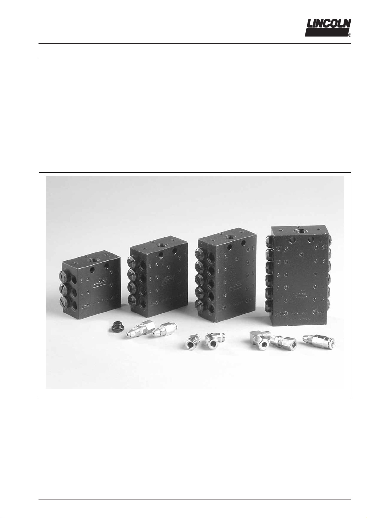
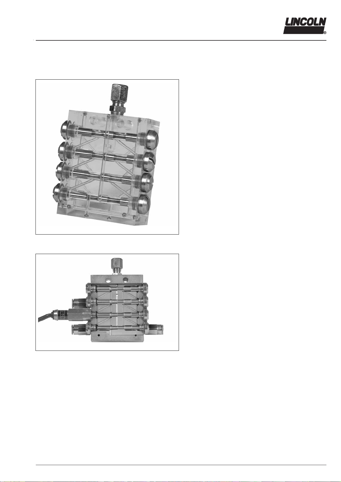
Appropriate Use
Use the SSV and SSV M lubricant metering devices only for
dispensing lubricants in centralized lubrication systems.
Suitable Lubricants
The progressive metering devices model SSV can be used
for dispensing
- mineral oils of at least 40 mm²/s (cST) or
- greases up to the penetration class NLGI 2
6001a02
IMPORTANT
It must nevertheless be ensured that the
oils or greases used do not alter their con-
sistency significantly in the course of time o
under the influence of temperature or
pressure.
General Safety Instructions
The progressive centralized lubrication system connected
to the Quicklub pump model 203 must always be secured
with a pressure relief valve.
Lincoln SSV and SSV M lubricant metering devices are
state of the art.
Incorrect use may result in bearing damage caused by
poor or over-lubrication.
Each outlet which will be used must be equipped with a
check valve.
In the case of the metering devices model SSV 6 - 12
the outlets 1 and/or 2 must never be closed. In the case of
the assembled metering devices model SSV 14 - 22,
the two outlets with the highest numbers must never be
closed.
Unauthorized modifications or changes to an installed
system are not admissible. Any modification must be
subject to prior consultation with the manufacturer of the
lubrication system.
Use only original Lincoln spare parts (see Parts Catalogue)
or the parts approved by Lincoln.
Regulations for Prevention of Accidents
Adhere to the regulations forpreventionof accidents which are
effective in the country where the system is to be used.
1013A94
CAUTION!
Danger of injury in the case of serious
corrosion of metering device surfaces:
n increasing corrosion of the surfaces will
cause the balls pressed in to lose their hold.
Under pressure, they may suddenly burst
out and cause injuries.
For applications in corrosive environments,
use metering devices in stainless steel
version only.
Operation, Repair and Maintenance
Authorized and instructed personnel who are familiar with the
centralized lubrication systems should only perform repair.
Installation
Install the metering devices at a suitable location in ac-
cordance with the lubrication diagram.
It is recommended that the metering devices be installed in
such a way that the outlets are not close to the chassis or
the attaching plate. This will facilitate troubleshooting in the
case the system is blocked.
The main metering devices with indicator pin must be
installed in such a way that the indicator pin is easily visible.
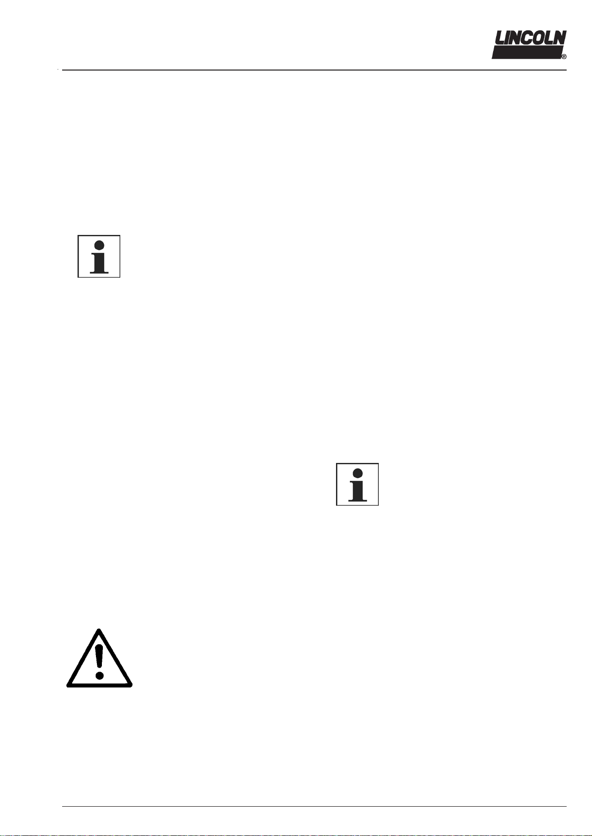
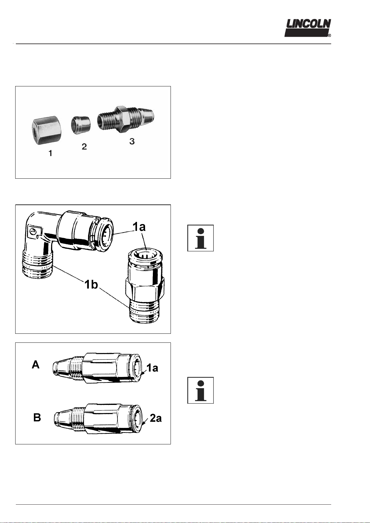
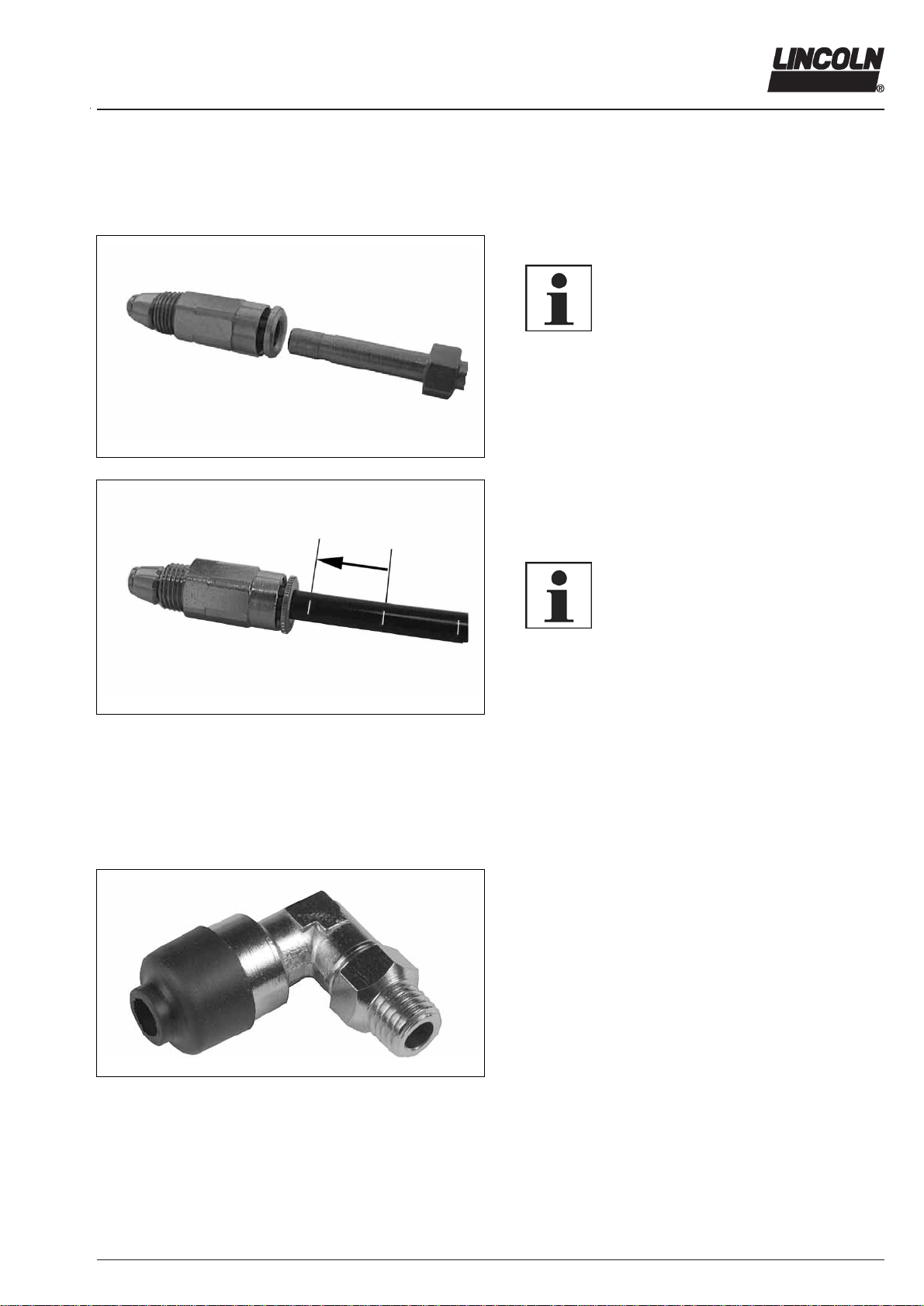
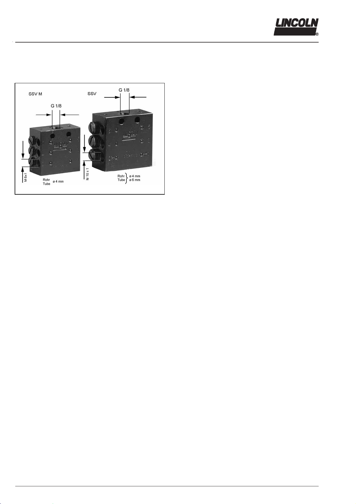
When the push-in type fittings are used, note the follow-
ing:
For the metering device inlet use only push-in type
fittings (R 1/8) with reinforced collar and sealing ring.
For the outlet tube fittings of the SSV divider valve
(M 10x1) depending on the design of the lubricant line, for
example
- high-pressure plastic hose (ø 4.1 x 2.3) use valve bodies
with reinforced collar only, or,
- pressure plastic tube (ø 6 x 1.5) use valve bodies with
knurled collar only
For the outlet fittings of the SSV M divider divider valve
(M 8x1) pressure plastic tube (ø 4 x 1) use valve bodies
with knurled collar only.
6001a02
NOTE
In the case of construction machines or
agricultural machines use high pressure
plastic hoses for the lubricant feet lines. In
such cases the outlet fittings of the sec-
ondary metering devices and the connec-
tion fittings to the lubricant points must
have a reinforced collet.
Use only the main and feed lines specified by Lincoln and
adhere to the specified system pressures.