Batco 2035 User manual

Read this manual before using product. Failure to
follow instructions and safety precautions can
result in serious injury, death, or property
damage. Keep manual for future reference.
Part Number: P1512021 R6
Revised: August 2017
Portable Grain Belt Conveyor
Standard
Assembly Manual
This manual applies to:
2000 Series: 2035, 2045, 2055, 2065, 2075, 2085, 2095, 20105, 20110, 20120
2400 Series: 2465, 2475, 2485, 2495, 24105, 24110, 24120
Original Instructions

New in this Manual
The following changes have been made in the Rev 6 (August 2017) revision of the manual:
Description Section
Added the missing assembly instructions for cable
bridge (55’-95’), truss cables (55’-95’), truss towers
(105’ — 120’), and truss cables (105’ — 120’).
Section 4.12. – Install the Cable Bridge (55' — 95'
Models) on page 45
Section 4.13. – Install the Truss Cables (55' — 95'
Models) on page 49
Section 4.14. – Install the Truss Towers and Truss
Tubes (105' — 120' Models) on page 55
Section 4.15. – Install the Truss Cables (105' — 120'
Models) on page 59
The following changes have been made in the Rev 5 (June 2017) revision of the manual:
Description Section
Added scissor frame assembly procedure for 65' —
95' scissor frame conveyors.
Section 4.27. – Assemble the Scissor-Lift Frame (65'
— 95' Models) on page 92
The following changes have been made in the Rev 4 (May 2017) revision of the manual:
Description Section
Formatting and restructuring updates Throughout
New hardware components. Added previously
missing cross brace.
Section 4.25. – Assemble the A-Frame (35' – 55'
Models) on page 88
New hardware components. New hydraulic cylinder
orientation.
Section 4.28. – Assemble the Scissor-Lift Frame (105'
— 120' Models) on page 96
New fittings and components. Section 4.30. – Plumb the Scissor-Lift Frame Hydraulic
Cylinders (105’ – 120’ Models) on page 108

PORTABLE GRAIN BELT CONVEYOR – STANDARD
P1512021 R6 3
CONTENTS
1. Introduction ............................................................................................................................................ 5
2. Safety....................................................................................................................................................... 7
2.1. Safety Alert Symbol and Signal Words..................................................................................... 7
2.2. General Safety .......................................................................................................................... 7
2.3. Moving Conveyor Belt Safety................................................................................................... 8
2.4. Rotating Parts Safety................................................................................................................ 8
2.5. Drives and Lockout Safety........................................................................................................ 8
2.5.1 Electric Motor Safety.................................................................................................. 9
2.5.2 PTO Driveline Safety................................................................................................... 9
2.5.3 Hydraulic Power Safety ............................................................................................ 10
2.6. Tire Safety............................................................................................................................... 11
2.7. Personal Protective Equipment.............................................................................................. 12
2.8. Safety Equipment ................................................................................................................... 12
2.9. Safety Decals .......................................................................................................................... 13
2.9.1 Decal Installation/Replacement............................................................................... 13
2.9.2 Safety Decal Locations and Details .......................................................................... 13
3. Features................................................................................................................................................. 27
3.1. Model Number ....................................................................................................................... 30
4. Assembly ............................................................................................................................................... 31
4.1. Assembly Safety ..................................................................................................................... 31
4.2. Check Shipment...................................................................................................................... 31
4.3. Required Tools........................................................................................................................ 32
4.4. Before You Begin.................................................................................................................... 32
4.5. Component Locations ............................................................................................................ 33
4.6. S-Drive Assembly .................................................................................................................... 33
4.7. Assemble the Conveyor Tube ................................................................................................ 37
4.8. Install the Tube Lift Components (35' – 55' Models) ............................................................ 38
4.9. Install the Hand Winch (35' – 55' Models) ............................................................................ 40
4.10. Install the Hitch .................................................................................................................... 41
4.11. Attach the S-Drive ................................................................................................................ 43
4.12. Install the Cable Bridge (55' — 95' Models) ........................................................................ 45
4.12.1 Install the Cable Return Bracket (2055 Model Only)............................................. 47
4.13. Install the Truss Cables (55' — 95' Models)......................................................................... 49
4.13.1 Truss Cables For 55' and 65' Models ..................................................................... 49
4.13.2 Truss Cables For 75' — 95' Models........................................................................ 51
4.13.3 Secure the Cables to the Anchor Brackets ............................................................ 53
4.13.4 Tighten the Truss Cables ........................................................................................ 54
4.14. Install the Truss Towers and Truss Tubes (105' — 120' Models) ........................................ 55
4.15. Install the Truss Cables (105' — 120' Models)..................................................................... 59
4.15.1 Secure the Cables to the Turnbuckle Eyebolts ...................................................... 60
4.15.2 Tighten the Truss Cables ........................................................................................ 62
4.16. Assemble the Weather Guard.............................................................................................. 62
4.17. Install the Guiding Roller (2045 Model Only) ...................................................................... 67
4.18. Install the Belt ...................................................................................................................... 68
4.19. Install the Hopper Belt Guard (55' — 120' Models) ............................................................ 73
4.20. Install the Weather Guard Mount Bar ................................................................................. 75

PORTABLE GRAIN BELT CONVEYOR – STANDARD
4 P1512021 R6
4.21. Install the Collapsible Hopper Cloth .................................................................................... 79
4.22. Install the Spout Bottom Cover............................................................................................ 85
4.23. Install the Spout Hood.......................................................................................................... 86
4.24. Install the Wheels................................................................................................................. 87
4.25. Assemble the A-Frame (35' – 55' Models)........................................................................... 88
4.26. Install the Tube Lift Cable (35' – 55' Models) ...................................................................... 89
4.27. Assemble the Scissor-Lift Frame (65' — 95' Models) .......................................................... 92
4.28. Assemble the Scissor-Lift Frame (105' — 120' Models) ...................................................... 96
4.29. Plumb the Scissor-Lift Frame Hydraulic Cylinders (65’ – 95’ Models)............................... 106
4.30. Plumb the Scissor-Lift Frame Hydraulic Cylinders (105’ – 120’ Models)........................... 108
4.31. Drive Assemblies ................................................................................................................ 109
4.31.1 Install the Side PTO .............................................................................................. 109
4.31.2 Install the Front PTO Drive (2000 and 2400 Series) ............................................ 112
4.31.3 Install the Electric Drive (2000 Series) ................................................................. 120
4.31.4 Install the Electric Drive (2400 Series) ................................................................. 122
4.31.5 Install the Hydraulic Wet Kit to Electric Drive (2000 Series) ............................... 126
4.31.6 Install the Hydraulic Wet Kit to Electric Drive (2400 Series) ............................... 129
4.32. Install the Shaft Guard ....................................................................................................... 133
4.33. Install the Inspection Step.................................................................................................. 134
4.34. Install the Manual Container ............................................................................................. 135
4.35. Attach the Jack ................................................................................................................... 136
5. Specifications for S-Drive Standard Conveyor (2000 Series: 35' — 55') .......................................... 137
6. Specifications for S-Drive Standard Conveyor (2000 and 2400 Series: 65' — 120')........................ 138
7. Appendix ............................................................................................................................................. 139
7.1. Bolt Torque........................................................................................................................... 139
8. Batco Limited Warranty ..................................................................................................................... 140

P1512021 R6 5
1. Introduction
This manual describes how to assemble a Batco Portable Grain Belt Conveyor.
Before assembling the conveyor, please read this manual. Familiarize yourself with the process and the
necessary precautions for efficient and safe assembly.
Everyone present at the assembly site is required to be familiar with all safety precautions.
Keep this manual available for frequent reference and review it with new personnel. Call your local
distributor or dealer if you need assistance or additional information.
PORTABLE GRAIN BELT CONVEYOR – STANDARD 1. INTRODUCTION

6 P1512021 R6
1. INTRODUCTION PORTABLE GRAIN BELT CONVEYOR – STANDARD

P1512021 R6 7
2. Safety
2.1. Safety Alert Symbol and Signal Words
This safety alert symbol indicates important safety messages in this manual. When you see
this symbol, be alert to the possibility of injury or death, carefully read the message that
follows, and inform others.
Signal Words: Note the use of the signal words DANGER,WARNING,CAUTION, and NOTICE with the safety
messages. The appropriate signal word for each message has been selected using the definitions below as a
guideline.
Indicates an imminently hazardous situation that, if not avoided, will result in serious injury or
death.
Indicates a hazardous situation that, if not avoided, could result in serious injury or death.
Indicates a hazardous situation that, if not avoided, may result in minor or moderate injury.
Indicates a potentially hazardous situation that, if not avoided, may result in property damage.
2.2. General Safety
The safety information in the safety section of this manual applies to all safety practices. Specific safety
information (such as Operation Safety), can be found in the appropriate section.
YOU are responsible for the SAFE use and maintenance of your conveyor. YOU must ensure that you and
anyone else who is going to work around the conveyor understands all procedures and related SAFETY
information contained in this manual.
Remember, YOU are the key to safety. Good safety practices not only protect you, but also the people around
you. Make these practices a working part of your safety program. All accidents can be avoided.
• It is the conveyor owner, operator, and maintenance personnel's responsibility to
read and understand ALL safety instructions, safety decals, and manuals and follow
them when assembling, operating, or maintaining the equipment.
• Owners must give instructions and review the information initially and annually with all personnel before
allowing them to operate the conveyor. Untrained users/operators expose themselves and bystanders to
possible serious injury or death.
• The conveyor is not intended to be used by children.
• Use the conveyor for its intended purposes only.
• Do not modify the conveyor in any way without written permission from the manufacturer. Unauthorized
modification may impair the function and/or safety, and could affect the life of the conveyor. Any
unauthorized modification of the conveyor will void the warranty.
PORTABLE GRAIN BELT CONVEYOR – STANDARD 2. SAFETY

8 P1512021 R6
2.3. Moving Conveyor Belt Safety
• DO NOT step on or touch moving conveyor belt.
• Shut off and lock out power to adjust, service, or clean.
2.4. Rotating Parts Safety
• Keep body, hair, and clothing away from rotating pulleys,
belts, chains, and sprockets.
• Do not operate with any guard removed or modified. Keep
guards in good working order.
• Shut off and remove key or lock out power source before
inspecting or servicing machine.
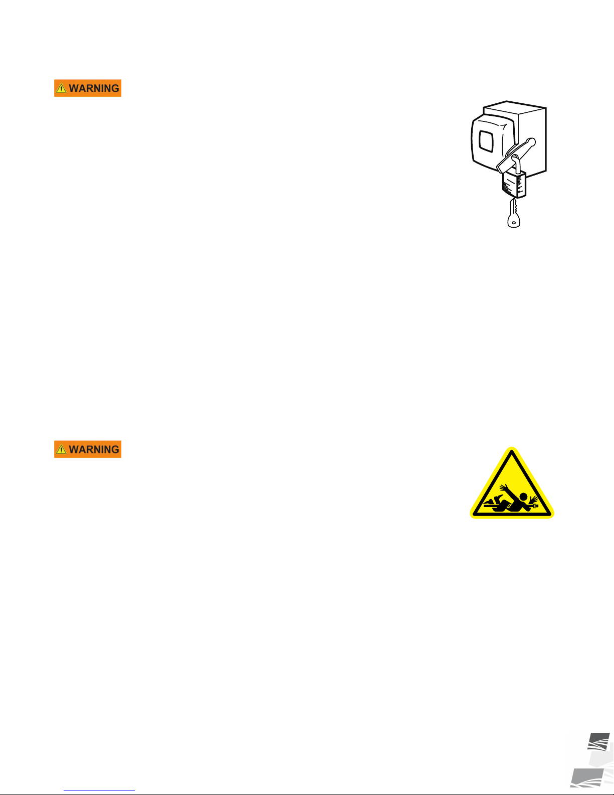
2.5. Drives and Lockout Safety
Inspect the power source(s) before using and know how to shut down in an emergency.
Whenever you service or adjust your equipment, make sure you shut down the power
source and unplug or remove the key (as applicable) to prevent inadvertent start-up and
hazardous energy release. Know the procedure(s) that applies to your equipment from the
following power source(s). Ensure that all personnel are clear before turning on power to
equipment.
2. SAFETY PORTABLE GRAIN BELT CONVEYOR – STANDARD
P1512021 R6 9
2.5.1 Electric Motor Safety
Power Source
• Electric motors and controls shall be installed and serviced by
a qualified electrician and must meet all local codes and
standards.
• A magnetic starter should be used to protect your motor.
• You must have a manual reset button.
• Reset and motor starting controls must be located so that the
operator has full view of the entire operation.
• Locate main power disconnect switch within reach from
ground level to permit ready access in case of an emergency.
• Motor must be properly grounded.
• Guards must be in place and secure.
• Ensure electrical wiring and cords remain in good condition;
replace if necessary.
• Use a totally enclosed electric motor if operating in
extremely dusty conditions.
SERVICE DISCONNECT
ON
OFF
Lockout
• The main power disconnect switch should be in the locked position during shutdown or
whenever maintenance is performed.
• If reset is required, disconnect all power before resetting motor.
2.5.2 PTO Driveline Safety
Drive
• Keep body, hair, and clothing away from rotating PTO
driveline.
• Make certain the driveline shields telescope and rotate freely
on driveline before attaching.
• Make certain the driveline is securely attached at both ends.
• Do not operate conveyor unless all driveline, tractor, and
equipment shields are in place and in good working order.
• Do not exceed operating speed of 540 rpm.
• Keep universal joint angles small and equal. Do not exceed
maximum recommended length for PTO driveline.
• Engage tractor park brake and/or chock wheels.
Lockout
• Position all controls in neutral, shut off tractor’s engine, and remove key from tractor.
• If removing key is impossible, remove PTO driveline from tractor.
PORTABLE GRAIN BELT CONVEYOR – STANDARD 2. SAFETY

10 P1512021 R6
2.5.3 Hydraulic Power Safety
Power Source
• Refer to the rules and regulations applicable to the power
source operating your hydraulic drive.
• Do not connect or disconnect hydraulic lines while system is
under pressure.
• Keep all hydraulic lines away from moving parts.
• Escaping hydraulic fluid under pressure will cause serious
injury if it penetrates the skin surface (serious infection or
toxic reaction can develop). See a doctor immediately if
injured.
• Use metal or wood as a backstop when searching for
hydraulic leaks and wear proper hand and eye protection.
• Check all hydraulic components are tight and in good
condition. Replace any worn, cut, abraded, flattened, or
crimped hoses.
• Clean the connections before connecting to equipment.
• Do not attempt any makeshift repairs to the hydraulic fittings
or hoses with tape, clamps, or adhesive. The hydraulic
system operates under extremely high pressure; such repairs
will fail suddenly and create a hazardous and unsafe
condition.
Lockout
• Always place all hydraulic controls in neutral and relieve
system pressure before disconnecting or working on
hydraulic system.
2. SAFETY PORTABLE GRAIN BELT CONVEYOR – STANDARD

P1512021 R6 11
2.6. Tire Safety
Failure to follow proper procedures when mounting a tire on a
wheel or rim can produce an explosion that may result in
serious injury or death.
• DO NOT attempt to mount a tire unless you have the proper
equipment and experience to do the job.
• Have a qualified tire dealer or repair service perform
required tire maintenance.
• When replacing worn tires, make sure they meet the original
tire specifications. Never undersize the replacement tire.
• DO NOT weld to the tire rim with the tire mounted on the
rim. This action may cause an explosion which could result in
serious injury or death.
• Inflate tires to the manufacturer’s recommended pressure.
• Tires should not be operated at speeds higher than their
rated speed.
• Keep wheel lug nuts tightened to manufacturer’s
recommendations.
• Never reinflate a tire that has been run flat or seriously
under-inflated without removing the tire from the wheel.
Have the tire and wheel closely inspected for damage before
remounting.
PORTABLE GRAIN BELT CONVEYOR – STANDARD 2. SAFETY

12 P1512021 R6
2.7. Personal Protective Equipment
The following Personal Protective Equipment (PPE) should be worn when assembling the equipment.
Safety Glasses
• Wear safety glasses at all times to protect eyes from debris.
Work Gloves
• Wear work gloves to protect your hands from sharp and rough edges.
Steel-Toe Boots
• Wear steel-toe boots to protect feet from falling debris.
Coveralls
• Wear coveralls to protect skin.
Hard Hat
• Wear a hard hat to help protect your head.
2.8. Safety Equipment
The following safety equipment should be kept on site:
Fire Extinguisher
• Provide a fire extinguisher for use in case of an accident. Store in a highly visible and
accessible place.
First-Aid Kit
• Have a properly-stocked first-aid kit available for use should the need arise, and
know how to use it.
2. SAFETY PORTABLE GRAIN BELT CONVEYOR – STANDARD

P1512021 R6 13
2.9. Safety Decals
• Keep safety decals clean and legible at all times.
• Replace safety decals that are missing or have become illegible. See decal location figures that follow.
• Replaced parts must display the same decal(s) as the original part.
• Replacement safety decals are available free of charge from your distributor, dealer, or factory.
2.9.1 Decal Installation/Replacement
1. Decal area must be clean and dry, with a temperature above 50°F (10°C).
2. Decide on the exact position before you remove the backing paper.
3. Align the decal over the specified area and carefully press the small portion with the exposed sticky backing
in place.
4. Slowly peel back the remaining paper and carefully smooth the remaining portion of the decal in place.
5. Small air pockets can be pierced with a pin and smoothed out using the sign backing paper.
2.9.2 Safety Decal Locations and Details
Replicas of the safety decals that are attached to the conveyor and their messages are shown in the figure(s)
that follow. Safe operation and use of the conveyor requires that you familiarize yourself with the various safety
decals and the areas or particular functions that the decals apply to, as well as the safety precautions that must
be taken to avoid serious injury, death, or damage.
PORTABLE GRAIN BELT CONVEYOR – STANDARD 2. SAFETY

14 P1512021 R6
Figure 1. Safety Decal Locations (35' – 55' Conveyors)
P1513045
P1513038
P1513046
P1513039
P1513052
P1513037
P1513042 P1513001
2. SAFETY PORTABLE GRAIN BELT CONVEYOR – STANDARD

P1512021 R6 15
Figure 2. Safety Decal Locations (65' — 120' Conveyors)
P1513045
P1513037
P1513001
P1513044
P1513010
P1513035
P1513052
P1513046 P1513030 P1513042
Figure 3. S-Drive Safety Decal Location
P1513022
PORTABLE GRAIN BELT CONVEYOR – STANDARD 2. SAFETY
16 P1512021 R6
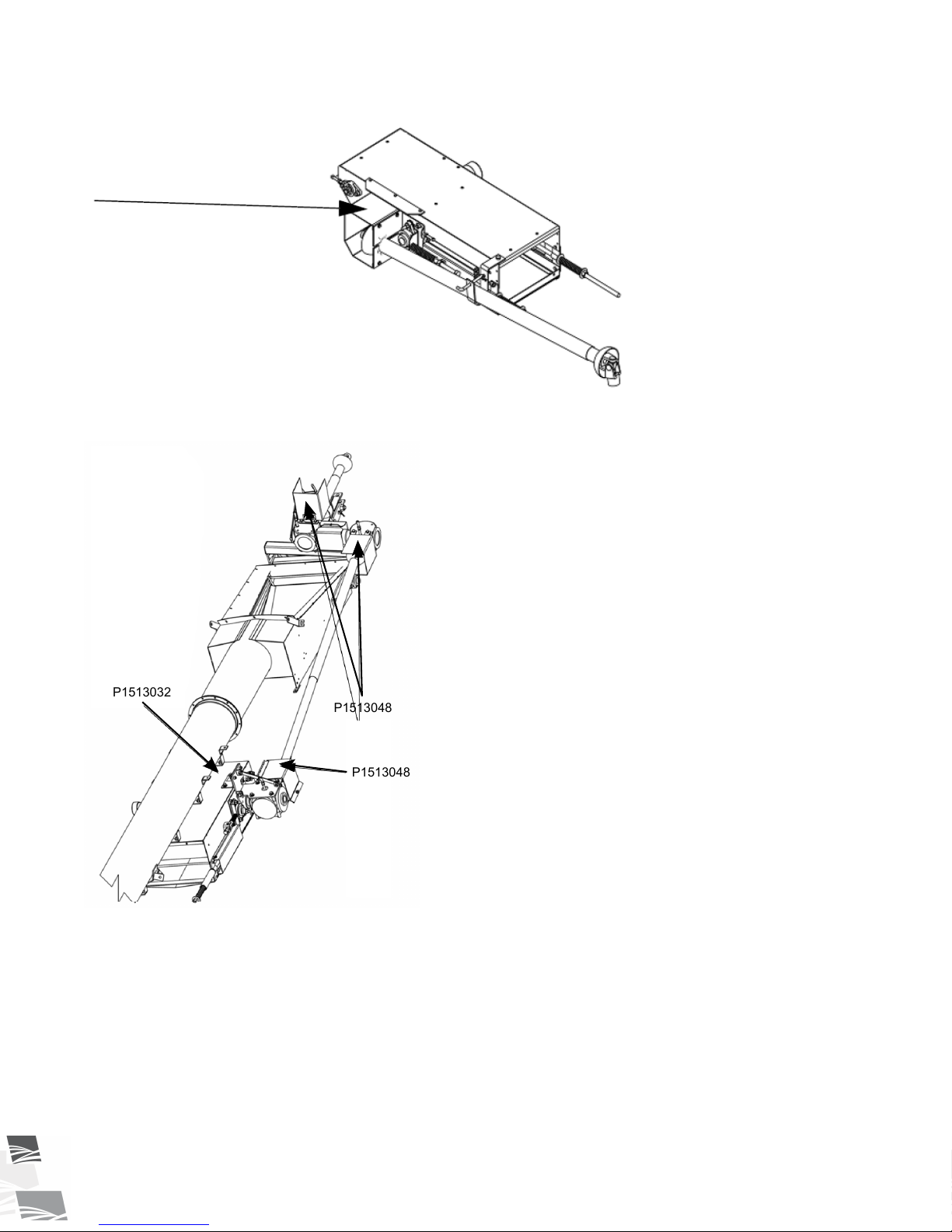
Figure 4. Side PTO S-Drive Safety Decal Location
P1513048
Figure 5. Front PTO S-Drive Safety Decal Locations
P1513032
P1513048
P1513048
2. SAFETY PORTABLE GRAIN BELT CONVEYOR – STANDARD

P1512021 R6 17
Figure 6. Electric Drive Safety Decal Locations
P1513008
P1513009
P1513002
PORTABLE GRAIN BELT CONVEYOR – STANDARD 2. SAFETY

18 P1512021 R6
Table 1. Safety Decals
Part Number Description
P1513046
To prevent death or serious injury:
• When operating or moving, keep equipment away from
overhead power lines and devices.
• Fully lower equipment before moving.
This equipment is not insulated.
Electrocution can occur without direct contact.
ELECTROCUTION HAZARD
DANGER
Country of Origin Part Number
P1513048
DANGER
ROTATING PTO DRIVELINE
HAZARD
To prevent serious injury or death:
•Keep body, hair, and clothing away from rotating
PTO driveline.
•Do not operate equipment unless all driveline,
tractor, and equipment shields are in place and in
good working order.
•Make certain the driveline shields turn freely on
driveline.
•Make certain the driveline is securely attached at
both ends.
•Do not exceed operating speed of 1000 rpm.
•Keep u-joint angles small and equal. Do not
exceed maximum recommended length for PTO
driveline.
DANGER
To prevent serious injury or death:
• Keep body, hair, and clothing away from rotating
PTO driveline.
• Do not operate equipment unless all driveline,
tractor, and equipment shields are in place and
in good working order.
• Make certain the driveline shields turn freely on
driveline.
• Make certain the driveline is securely attached
at both ends.
• Do not exceed operating speed of 540 rpm.
• Keep u-joint angles small and equal. Do not
exceed maximum recommended length for PTO
driveline.
ROTATING PTO DRIVELINE
HAZARD
Country of Origin Part Number
2. SAFETY PORTABLE GRAIN BELT CONVEYOR – STANDARD
P1512021 R6 19
Table 1 Safety Decals (continued)
Part Number Description
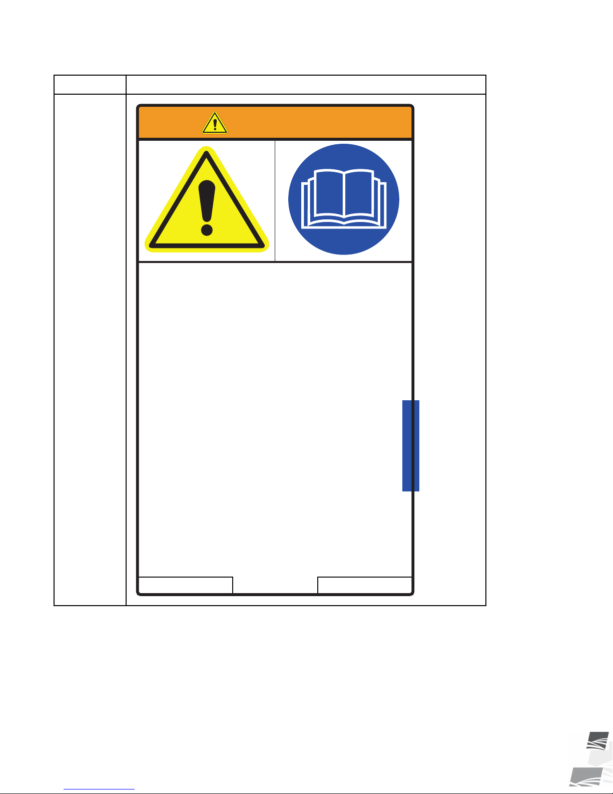
P1513001
Country of Origin Part Number
To prevent serious injury or death:
• Read and understand the manual before
assembling, operating, or maintaining the
equipment.
• Only trained personnel may assemble, operate,
or maintain the equipment.
• Children and untrained personnel must be kept
outside of the work area.
• Do not modify the equipment. Keep in good
working order.
• If the manual, guards, or decals are missing or
damaged, contact factory or dealer for
replacements.
• Lock out power before performing maintenance.
• To prevent equipment collapse, support equipment
tube while disassembling certain components.
• Electric motors must be grounded. Disconnect
power before resetting overloads.
WARNING
PORTABLE GRAIN BELT CONVEYOR – STANDARD 2. SAFETY
20 P1512021 R6
Table 1 Safety Decals (continued)
Part Number Description
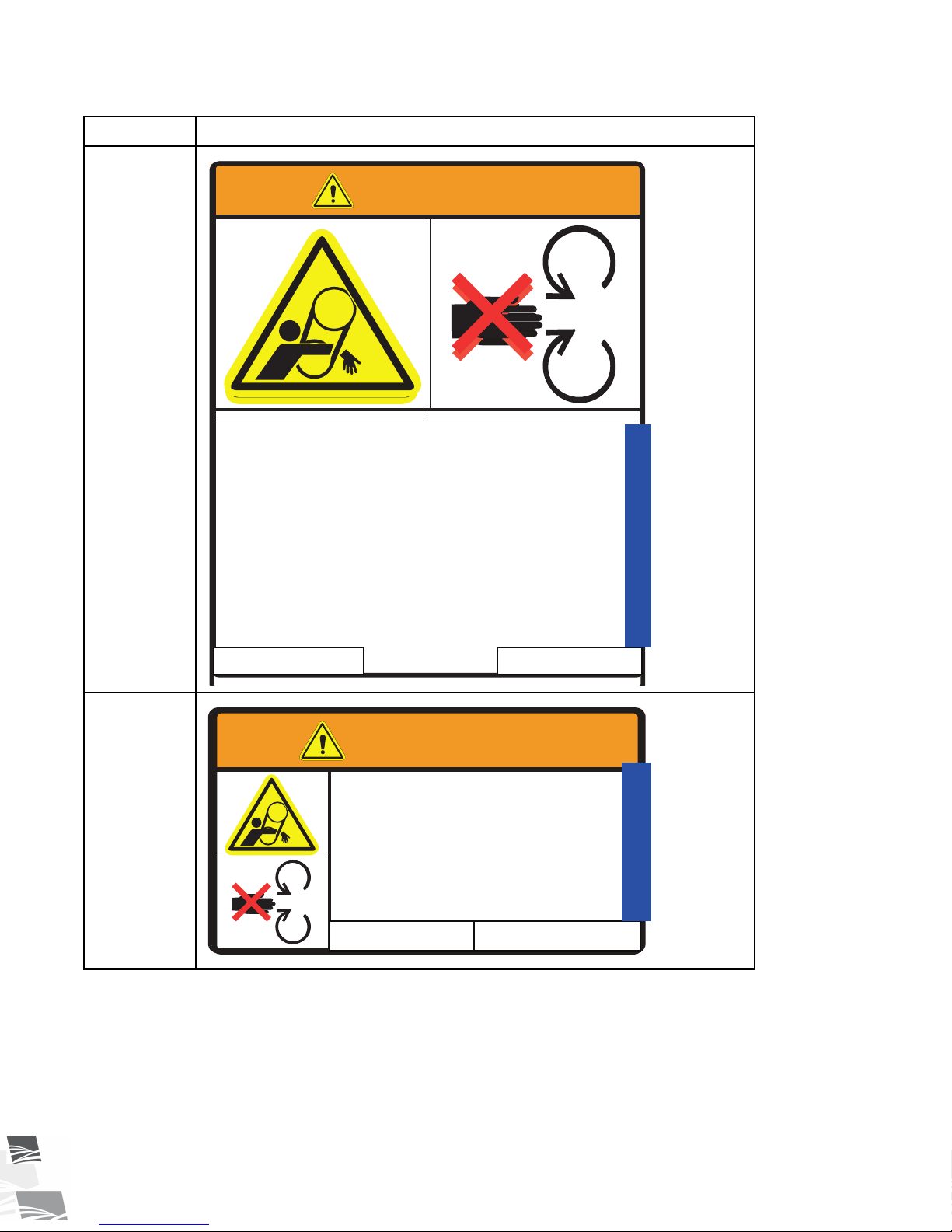
P1513002
WARNING
ENTANGLEMENT HAZARD
To prevent serious injury or death:
•Keep body, hair, and clothing away from rotating
pulleys, belts, chains, and sprockets.
•Do not operate with any guard removed or
modified. Keep guards in good working order.
•Shut off and remove key or lock out power source
before inspecting or servicing machine.
To prevent serious injury or death:
• Keep body, hair, and clothing away from rotating
pulleys, belts, chains, and sprockets.
• Do not operate with any guard removed or
modified. Keep guards in good working order.
• Shut off and remove key or lock out power
source before inspecting or servicing machine.
ENTANGLEMENT HAZARD
WARNING
Country of Origin Part Number
P1513008
WARNING
MISSING GUARD HAZARD
To prevent serious injury or
death, shut off power and
reattach guard before operating
machine.
To prevent serious injury or
death, shut off power and
reattach guard before operating
machine.
MISSING GUARD HAZARD
WARNING
Country of Origin Part Number
2. SAFETY PORTABLE GRAIN BELT CONVEYOR – STANDARD
This manual suits for next models
16
Table of contents
Other Batco Accessories manuals


