BatteryMINDer 24041-AA Series User manual
READ AND SAVE THESE
INSTRUCTIONS
VDC Electronics, Inc. •155 W. Carver St., Ste. 2 • Huntington, NY 11743
BatteryMINDer®
24041-AA-Series
24-Volt Aviation-Calibrated
Charger / Maintainer / Desulfator
INSTRUCTION MANUAL
All Models Include (except where indicated):
• 2’ Battery Clip Cord Set (non-insulated) with Quick Connector (-S2 & -S3)
• 2’ Battery Clip Cord Set (insulated) with Quick Connector (-S5)
• 2’ Ring Terminal Cord Set with Quick Connector (-S2 & -S3)
• One Ambient Temperature Sensor (ATS-1) (see Simple Operating
Instructions)
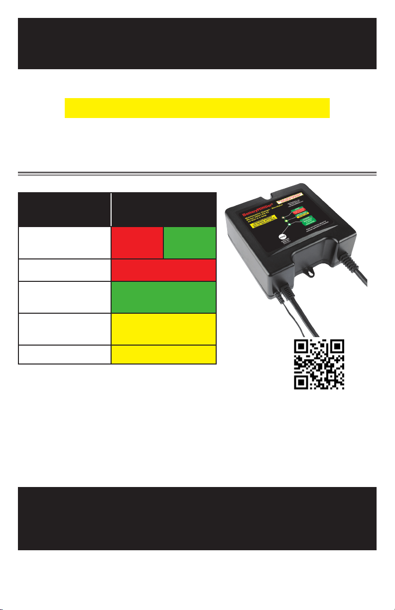
BATTERY TYPE RECOMMENDED
CHARGER MODEL
CONCORDE
FLOODED S2 S5
GILL FLOODED S2
CONCORDE
SEALED RG S5 ONLY
HAWKER-
ODYSSEY S3 ONLY
GILL LT/7000 S3
Rev. B-062613 P/N VDC24041-AA-Sx-MNL

BatteryMINDer® Aviation-Adjusted Models 24041-AA-S2, S3 & S5
Rev. B-062613 Page 2 P/N VDC24041-AA-Sx-MNL
Glossary of Terms
• Maintain a battery
BatteryMINDer ensures batteries are truly fully charged and will likely
continue improving the condition of the battery to the fullest extent
possible.
• Rested
A battery that has been as fully charged as possible and left disconnected
from charger or any type load overnight.
• Specific Gravity
One of the key parameters of battery operation is the specific gravity of the
electrolyte. Specific gravity is the ratio of the weight of a solution to the
weight of an equal volume of water at a specified temperature. Specific
gravity is used as an indicator of the state of charge of a cell or battery.
• Sulfation
Occurs when the battery sits discharged for a long period of time and large
sulfate crystals build up in the plates. The large sulfate crystals increase
the resistance of the plates and makes the battery harder to recharge.
Table Of Contents
Required Safety Instructions . . . . . . . . . . . . . . . . . . . . . . . . . . . . 3
Preparing to Charge . . . . . . . . . . . . . . . . . . . . . . . . . . . . . . . . 4
DC Connection Precautions . . . . . . . . . . . . . . . . . . . . . . . . . . . . 4
Unit Location . . . . . . . . . . . . . . . . . . . . . . . . . . . . . . . . . . . 4
Qualifying Your Battery . . . . . . . . . . . . . . . . . . . . . . . . . . . . . . 5
Charging a Filler Cap Lead-Acid Battery . . . . . . . . . . . . . . . . . . . . . . 6
Specific Gravity – Capacity Table. . . . . . . . . . . . . . . . . . . . . . . . . . 6
Testing With a Hot/Cold Calibrated Hydrometer Tester . . . . . . . . . . . . . . . 6
Testing A Sealed, AGM or Flooded (Wet-Cell) Lead Acid Battery . . . . . . . . . . 7
Use a Digital Voltmeter Only . . . . . . . . . . . . . . . . . . . . . . . . . . . . 7
Common Features . . . . . . . . . . . . . . . . . . . . . . . . . . . . . . . . . 8
Simplified Operating Instructions . . . . . . . . . . . . . . . . . . . . . . . . . 9
All Unit Labels and Descriptions . . . . . . . . . . . . . . . . . . . . . . . . . .10
Battery State of Charge Table . . . . . . . . . . . . . . . . . . . . . . . . . . .11
LED Status Table. . . . . . . . . . . . . . . . . . . . . . . . . . . . . . . . . .11
Detailed Operating Instructions . . . . . . . . . . . . . . . . . . . . . . . . . .12
OCV/Battery State of Charge Table . . . . . . . . . . . . . . . . . . . . . . . . .13
Temperature and its Effect on Batteries . . . . . . . . . . . . . . . . . . . . . .16
Charge and Float Voltages at Various Temperature Ranges . . . . . . . . . . . . .17
Maintaining Multiple Batteries . . . . . . . . . . . . . . . . . . . . . . . . . . .18
Multi-Battery Configuration . . . . . . . . . . . . . . . . . . . . . . . . . . . .19
Troubleshooting . . . . . . . . . . . . . . . . . . . . . . . . . . . . . . . .20-21
Detailed Specifications . . . . . . . . . . . . . . . . . . . . . . . . . . . . . . 22
For Repair or Replacement / Registration . . . . . . . . . . . . . . . . . . . . 23
Guarantee/Warranty . . . . . . . . . . . . . . . . . . . . . . . . . . . . . . . .24

BatteryMINDer® Aviation-Adjusted Models 24041-AA-S2, S3 & S5
Rev. B-062613 Page 3 P/N VDC24041-AA-Sx-MNL
REQUIRED SAFETY INSTRUCTIONS
WARNING
READ AND FULLY UNDERSTAND BEFORE OPERATING
Contact VDC Electronics if uncertain
about any settings or operation.
TO REDUCE THE RISK OF FIRE, ELECTRIC SHOCK, OR
INJURY TO PERSON, OBSERVE THE FOLLOWING:
• This unit is designed for protected use and should never be exposed
to rain.
• Do not attempt to use the unit if it has been dropped or damaged.
• Never attempt to charge a damaged battery, frozen battery or non-
rechargeable battery.
• Do not use the unit in a closed area or poorly ventilated area.
• Never smoke, use an open flame, or create sparks near a battery or unit
during charging operation as this may cause an explosion / explosive
gas.
• Do not operate the unit if the cord or plug is damaged.
• Do not disassemble. VDC Electronics MUST be contacted for repair,
replacement or analysis. Keep away from infants, children and pets.
• Switch off or remove AC power before connecting or disconnecting to
battery.
• Refer to the battery Manufacturer’s specific recommended values to
determine if standard unit settings are correct. Contact VDC Electronics
Tech Support before making any changes
• Check Battery Manufacturer’s specific precautions - such as removing
or not removing battery from aircraft before charging.
• Always remove battery from aircraft before equalizing or desulfating.
• Someone should be within range of your voice or close enough to
come to your aid if working near a lead-acid battery.
• Wear protective goggles and turn your face away when connecting or
disconnecting a battery.
• If battery acid contacts your skin or clothing, wash immediately with
soap and water. If acid enters your eye, immediately flush the eye with
running cold water for at least 10 minutes and seek medical attention
immediately.
• To reduce risk of damaging the battery, avoid dropping any metal tools
onto the battery.
• Never rest your Battery Charger on top of the Battery being charged.
• The Battery Charger / power supply should be kept as far away from
the Battery as the output cables permit.

BatteryMINDer® Aviation-Adjusted Models 24041-AA-S2, S3 & S5
Rev. B-062613 Page 4 P/N VDC24041-AA-Sx-MNL
Always follow battery manufacturer’s strict instructions for
proper care, charging and testing of battery. Always use their
FAA Approved “Instructions for Continued Airworthiness” (ICA).
Questions relating to the subject should be referred directly to
the battery manufacturer to be certain of current requirements
that may have been added to or changed since publication of their
instructions.
NEVER CHARGE A FROZEN BATTERY OR ONE AT A TEMPERATURE
ABOVE 123° F.
PREPARING TO CHARGE
A. Always remove ground wire first.
B. Be sure area around battery is well ventilated while battery is being
charged. Force gas vapors away by using a fan.
C. Clean battery terminals. Be careful to keep corrosion from contacting
eyes.
D. Study all battery manufacturer’s specific instructions such as
recommended charge rates.
E. Determine condition of battery, by referring to instructions herein,
before ever attempting to charge or desulfate any / all batteries.
F. Make sure unit is as far away from battery as output cables permit.
G. Never place unit directly above battery being charged; gases from
battery will corrode and damage unit.
H. Never allow battery acid to drip on charger when reading specific
gravity or filling.
I. Do not operate unit in a closed-in area or restrict ventilation in any
way.
J. Do not set battery on top of unit.
DC CONNECTION PRECAUTIONS
Note: Steps to be done in a well ventilated area away from aircraft.
A. Connect and disconnect DC output clips from battery only after
removing unit power cord from outlet.
B. Attach clips to battery posts and twist or rock back and forth several
times to make good contact. This tends to keep clips from slipping
off terminals and reduces risk of sparking.
UNIT LOCATION
A spark near the battery may cause battery explosion. To reduce
risk of a spark near battery:
A. Check polarity of battery posts. POSITIVE (POS, P, +) usually has a
larger diameter than NEGATIVE (NEG, N, -) battery post.

BatteryMINDer® Aviation-Adjusted Models 24041-AA-S2, S3 & S5
Rev. B-062613 Page 5 P/N VDC24041-AA-Sx-MNL
B. Connect (RED) charger clip to (POS+) post of battery.
C. Position yourself and free end of cable as far away from battery as
possible, then connect NEGATIVE (BLACK) charger clip.
D. Do not face battery when making final connections.
E. When disconnecting unit, always do so in reverse sequence of
connecting procedure and break first connection while as far
away from battery as practical. Do not attempt to permanently
install unit not specifically designed-approved for permanent
installation, especially in a wet high moisture environment.
NOTE: Because some batteries are not easily accessible, for example
located in the wing, tail, under the seat or in a battery box, it is acceptable
to attach the positive alligator clip to the positive post of the battery
relay or solenoid that is directly connected to the positive terminal of the
battery and attach the negative alligator clip to a suitable aircraft ground
connection.
QUALIFYING YOUR BATTERY
Preliminary Requirements
NOTE: The BatteryMINDer has no electrical output unless it is
connected to a healthy battery. Testing the BatteryMINDer with a
voltmeter without the unit being connected across a good battery will
result in a false reading. If you experience any problems, or are not
sure of how to properly use or connect your BatteryMINDer, please
e-mail our Tech Support Dept. at: techsupport@vdcelectronics.com
or call our toll-free technical support line 800-379-5579 x206 (Eastern
Time) (USA & Canada ONLY). Be certain to leave your phone
number with the area code, time zone and the best time to call.
To gain the best result from your unit and to maximize the life and
performance of your batteries we strongly recommend you qualify (test)
your batteries before attempting to either charge-maintain or desulfate
them. Remember, even if you just purchased a “new” battery it may have
been subjected to storage conditions that have caused “sulfation” such
as an extended period at high temperature (≥80°F).
NOTE: If your battery is new and you are certain it was not subject
to conditions that could have caused sulfation*, even before you
purchased it, then you can disregard our recommendations for
qualifying / testing your battery, before using the BatteryMINDer.
*Such as high temperature storage (≥80°F) and/or allowed to self-
discharge to 24.8 volts or lower.

BatteryMINDer® Aviation-Adjusted Models 24041-AA-S2, S3 & S5
Rev. B-062613 Page 6 P/N VDC24041-AA-Sx-MNL
CHARGING A FILLER CAP LEAD ACID BATTERY
A. Carefully remove all filler caps from your battery.
B. Check the water-liquid electrolyte level. If the level is low or has ever
been below top of plates, severe lead plate sulfation has taken place.
Significant recharge/reconditioning time is needed to restore these
plates to a condition where the battery may be expected to function
normally.
C. Refill each cell with distilled water only to the liquid level indicator found
in each cell. Before proceeding further you must be thoroughly
familiar with the safety and operating instructions.
D. Recharge the battery with the BatteryMINDer to ensure that it is
slowly and completely charged before you determine its condition.
Allow battery to “REST”overnight for a minimum of 12 hours before
testing with a temperature compensated hydrometer and/or digital type
voltmeter only.
E. If the BatteryMINDer battery condition LED lights (YELLOW) within
72 hours (single battery) or no balls float in one or more cells, your
battery may be too far gone to be fully desulfated. Reconnect battery
to your BatteryMINDer. Allow battery to remain in maintenance mode
for a minimum of 72 hours, before re-test. Use a hot/cold calibrated
hydrometer tester for the most accurate results (see table) if you
see an increase in the Specific Gravity (SG) or voltage indicating
that there is an improvement in the battery’s condition, continue
desulfating for an additional 72 hours and retest the battery. Continue
this process until the SG or voltage readings no longer increase.
TESTING WITH A HOT/
COLD CALIBRATED
HYDROMETER TESTER
Read the tester instructions carefully for
most accurate readings.
A. When using the tester the first time
or after a long period of non-use,
fill the tester with the battery fluid
and let it sit for 1/2 hour or longer.
This will soak the balls in order to
give you more accurate readings.
Failure to do so will give you false
readings indicating a battery that
may not be in as good a condition
as you may have thought.
B. After inserting the tester in a cell,
gently tap the tester several times
Specific Gravity – Capacity
Temperature
Compensated
Hydrometer - meter or
4 ball type
Full
Capacity
Percentage
1.270 (4 Balls floating) 100%
1.250 (3 Balls floating) 75%
1.190 (2 Balls floating) 50%
1.150 (1 Balls floating) 25%
1.120 (0 Balls floating)
May denote shorted cell
or battery that has been
severely discharged and
may not be recoverable
0%

BatteryMINDer® Aviation-Adjusted Models 24041-AA-S2, S3 & S5
Rev. B-062613 Page 7 P/N VDC24041-AA-Sx-MNL
against the inside wall of each cell to dislodge air bubbles that will
cause more balls to float than should. Failure to do so will yield false
readings that indicate a battery that is not fully desulfated or does not
qualify for desulfation.
C. If no balls float in any cell, the cell is shorted. This means your battery
is beyond the point of being properly recharged or reconditioned-
desulfated. Dispose of the battery.
D. If each cell floats three (3) or more balls (or 1250 on gauge-type), your
battery can be reconditioned-desulfated.
E. Always rinse the tester with fresh water after every use. Failure to do
so will cause false readings.
CHARGING A SEALED, AGM OR FLOODED (WET-CELL)
LEAD ACID BATTERY
These batteries have no filler caps or manifold-type covers. Because you
cannot gain access to the interior of your battery you cannot test it with a
hydrometer.
USE A DIGITAL VOLTMETER ONLY
A. Recharge the battery with the BatteryMINDer to ensure it is as
completely charged as possible, before you determine its condition.
Allow battery to “REST” overnight before checking the open circuit
voltage with a digital voltmeter only. Failure to check a “RESTED”
battery will cause false readings. Be certain to read and understand
all safety related instructions (pages 3 - 7) before proceeding further.
B. Measure battery’s voltage, without any load attached. If the voltage is
less than 25.2 volts (Typically 75% of charge) the battery may be too
heavily sulfated to be fully recoverable. If voltage is 25.2V or higher
recovery can be expected, given sufficient time.
C. Connect the BatteryMINDer to the battery
D. Chargebatterytoitsmaximumlevel. Allowbatterytoremainforaminimum
of 72 hours before retesting. If improvement is seen, continue until
battery voltage reaches full capacity level or no further increase is seen.
Note: Do not expect to completely dissolve sulfate in a day. Long
established sulfate will require a longer period to be fully dissolved.
Be patient and you will rewarded with a “sulfate-free” battery. If not
seriously damaged by sulfate, battery has a very good chance of
meeting 85% Cap (Airworthy) Test.
BatteryMINDer® Aviation-Adjusted Models 24041-AA-S2, S3 & S5
Rev. B-062613 Page 8 P/N VDC24041-AA-Sx-MNL
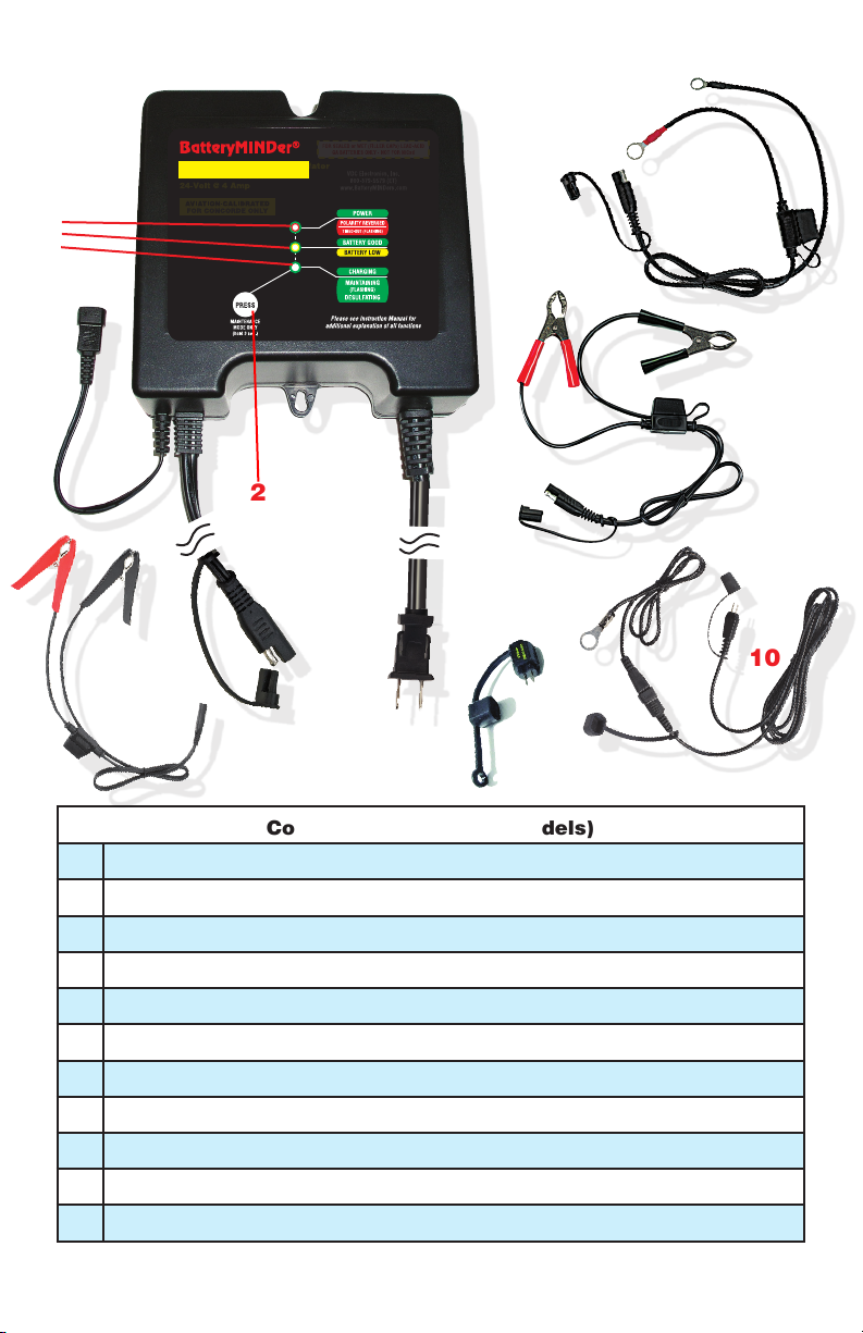
Common Features (All Models)
1LED indicators (a, b & c) (See Battery Condition and LED Status page)
2Maintenance Mode ONLY button
3Temperature Sensor input connector
4Output cord with quick connect plug
5Input power cordset
6Mounting tabs
7Ring Terminal cordset with quick connect plug (included on -S2 & -S3)
8Battery Clip (non-insulated) cordset with quick connect plug (included on -S2 & -S3)
9Battery Clip (insulated) cordset with quick connect plug (included on -S5)
10 ABS-248 At-the-Battery Temperature Sensor (optional)
11 ATS-1 Ambient Temperature Sensor (included)
7
8
10
11
9
2
6
5
6
3
1a
c
b
AVIATION-CALIBRATED
4

BatteryMINDer® Aviation-Adjusted Models 24041-AA-S2, S3 & S5
Rev. B-062613 Page 9 P/N VDC24041-AA-Sx-MNL
SIMPLIFIED OPERATING INSTRUCTIONS
Read and thoroughly understand ALL SAFETY Instructions, pages
3 - 7 including Preparing to Charge, DC Connection Precautions,
Unit Location and Qualifying Your Battery BEFORE proceeding
further.
1. Attach a battery connector assembly, either Ring Terminal Assembly
(7) or Battery Clips (8) (both supplied), to output cordset of charger
(4). NEVER CONNECT BOTH at the same time.
2. Attach output to battery terminals:
RED band = Positive +
BLACK band = Negative -.
3. Ambient Temperature Sensor, ATS-1 (10), comes already installed
on the Temperature Sensor input connector (3). Do not detach.
Either the Ambient Temperature Sensor (ATS-1) or the At-the-
Battery Temperature Sensor (ABS-248) (11) is mandatory when
used with all Aviation batteries.
4. Plug AC power cord (5) into a 120 Vac electrical outlet.
5. Observe Reversed Polarity GREEN/RED LED indicator (1a):
If lit RED, reverse battery connector attachments on battery.
6. Observe Charging - Maintenance/Desulfating GREEN LED
indicator (1c):
Solid = charging
Blinking = maintaining battery(s).
Charger will automatically start within 30 seconds or less.
7. Observe Battery Connected - Error LED Indicator (1a):
Must be lit GREEN1.
Be sure Maintaining - Desulfating LED (1c)is BLINKING before leaving
unit for an extended period of time. Otherwise, press & hold the
Maintenance button (2) for 3 seconds.
IF IN DOUBT REGARDING ANY OF THE ABOVE, REFER TO Detailed
Operating Instructions.
1See full instructions if not lit GREEN.
BatteryMINDer® Aviation-Adjusted Models 24041-AA-S2, S3 & S5
Rev. B-062613 Page 10 P/N VDC24041-AA-Sx-MNL
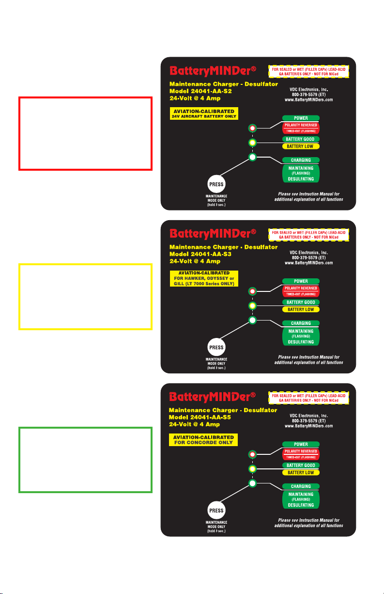
24041-AA-S2
Gill
(Sealed + Flooded Wet Cell) +
Concorde Flooded
24041-AA-S3
Hawker-Odyssey + Gill LT/7000
24041-AA-S5
Concorde
(Sealed Valve-Regulated AGM +
Flooded Wet Cell)
BatteryMINDer® Aviation-Adjusted Models 24041-AA-S2, S3 & S5
Rev. B-062613 Page 11 P/N VDC24041-AA-Sx-MNL
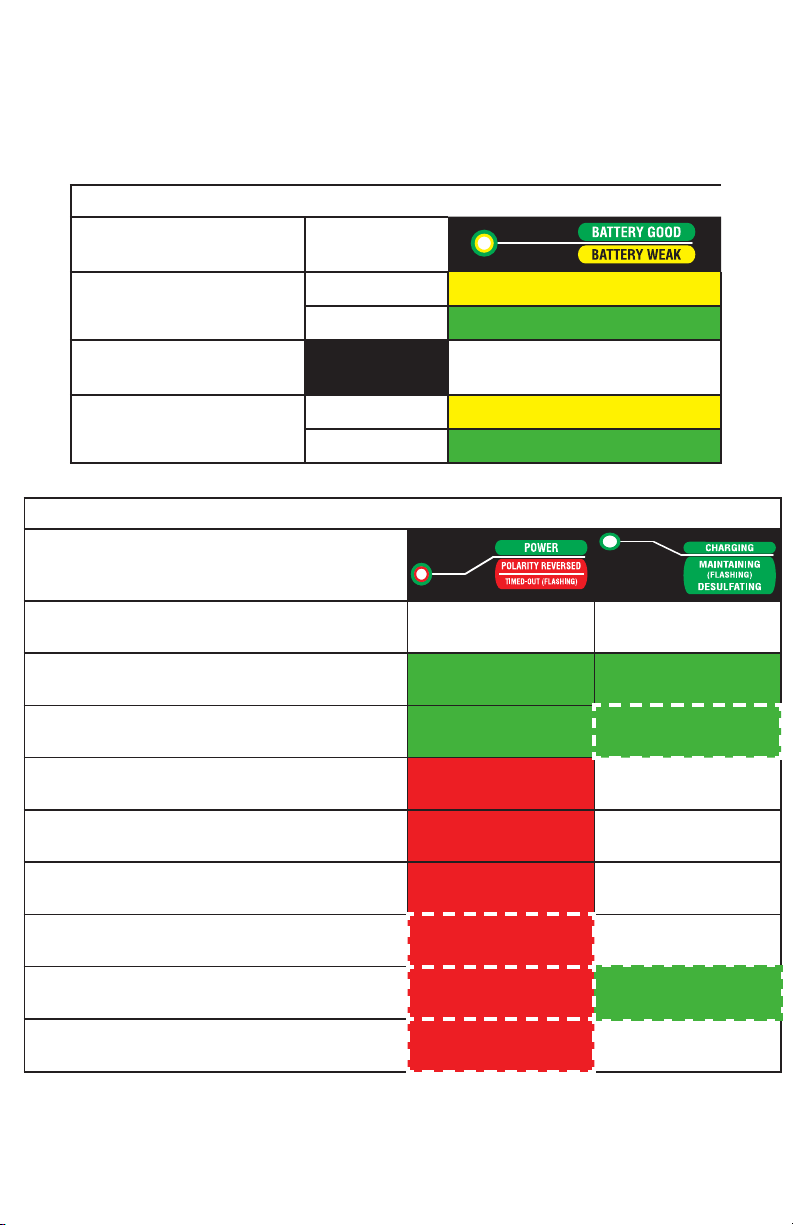
Battery State of Charge Table
Battery Condition Battery Voltage
(Vb)
BEFORE full charge <22
>22
Stop/Restart during charging
mode
Stops Charging. Press Again To
Restart.
AFTER full charge Low Voltage
Normal Voltage
LED Status Table
LED Status
(Power / Error and Charge LEDs)
A.C. power disconnected, battery connected
correctly OFF OFF
At Soft Start mode, Bulk charge mode or Absorption
mode ON ON
Float charge mode ON FLASHING
A.C. power connected Reversed Battery Polarity ON OFF
A.C. power connected, charger output clip shorted ON OFF
A.C. power connected, battery voltage <6V ON OFF
Timed-out when in SoftStart or Bulk mode FLASHING OFF
Timed-out when in Absorption mode & Forced to
Float mode FLASHING FLASHING
Battery Fault / Battery Weak FLASHING OFF

BatteryMINDer® Aviation-Adjusted Models 24041-AA-S2, S3 & S5
Rev. B-062613 Page 12 P/N VDC24041-AA-Sx-MNL
DETAILED OPERATING INSTRUCTIONS
Installed properly, your charger is set to provide your battery with what
it needs to out-live and out-perform any similar battery used in the
same application-conditions by a factor of two (2).
Read and thoroughly understand ALL SAFETY Instructions, pages
3 - 7 including Preparing to Charge, DC Connection Precautions,
Unit Location and Qualifying Your Battery BEFORE proceeding
further.
1. Attach output cord of charger to either the Battery Clip(s)
Assembly (BCA) (supplied) or the Ring Terminal Assembly (RTA)
(supplied) depending on your preference. However never use both
assemblies at the same time for any reason whatsoever. Using the
RTA on batteries remaining in their normal use location (in same
place they are regularly installed will normally prove the safest and
most convenient. If you have several applications you may wish
to purchase additional RTA’s available from your dealer or VDC
Electronics, Inc. directly.
2. Identify the positive and negative posts or connections on your
battery, usually clearly designated with the polarity markings of +
(positive) and – (negative). If you have previously installed the RTA
referred to in 1. above, you need only to press the connector plug
of the charger’s output cord into the mating plug of the RTA. Push
firmly and do not leave any space between them. Correct polarity
and a good connection will be your reward. Attach the BCA to
the proper battery posts, clamps or screw terminals, depending on
type of battery.
3. Your charger came with the Ambient Temperature Sensor
(ATS-1). The temperature sensor plugs into the mating receptacle
located on the charger at the end of a 2” long wire. The receptacle
is marked with a positive (+) and a negative (-) sign. The
temperature sensor can be inserted either way.
4. The At-the-Battery Temperature Sensor (ABS-248) is an
optional accessory which can be used in place of the ATS-1. This
temperature sensing system is made up of two components. The
thermal sensor with ring terminal and male plug with dust cover
with extension cord attached. This cord then attaches directly to
the mating female receptacle located on the charger.

BatteryMINDer® Aviation-Adjusted Models 24041-AA-S2, S3 & S5
Rev. B-062613 Page 13 P/N VDC24041-AA-Sx-MNL
Attaching the temperature sensor with extension cord:
Your first choice should be to connect it to the Positive (+) or Negative
(-) post (clamp / screw) of the battery. This is the best location to sense
the temperature of the battery.
5. The second choice is to place it as close to the battery as possible.
Attachment of the sensor to the side or top of battery is also
a possible option, under the right circumstances. Be careful to
ensure it will not come loose in service.
6. Plug the unit’s Power cord into a standard – grounded 120 Vac
electrical outlet. The Power On LED Indicator will light GREEN.
Within 30 seconds, if it does not light GREEN check the outlet to
be sure it is functioning. In addition, be sure if outlet is controlled
by a switch, no one will accidentally shut off the power to the outlet.
Check for correct polarity = (no ERROR RED LED Indicator). If
ERROR Indicator is lit, reverse the charger’s output connections
to the battery.
7. Charger will automatically start within 15 - 30 seconds. The Charge
– Float LED Indicator will light GREEN. The charger will now begin
charging by first checking the battery to determine its voltage and
ability to accept a charge. Should the battery not have a normal fully
discharged voltage (21.0V minimum) the unit will begin charging in
the “Soft-Start” mode to determine if the battery can be safely
charged. If it cannot, the Power On – Error LED will flash RED
and charging will be stopped. Battery should be carefully checked
under a load by a qualified
person before further
attempting to charge it.
Note: If the battery does
not have a minimum no
load OCV (Open Circuit
Voltage) of 6 volts,
the ERROR LED will
light RED and charger
will reject battery.
No further effort should be made to charge this battery with this
charger or any charger. Discard this battery, unless it has just
been subjected to a long period of continuous discharge under
OCV=Open Circuit No Load Voltage
OCV - “Rested” Voltage Full Capacity
Percentage
25.8 - 26.2 Volts 100%
25.2 - 25.8 Volts 75%
24.8 - 25.2 Volts 50%
24.4 - 24.8 Volts 25%
24.0 - 24.4 Volts 0%
<22 Volts could be shorted

BatteryMINDer® Aviation-Adjusted Models 24041-AA-S2, S3 & S5
Rev. B-062613 Page 14 P/N VDC24041-AA-Sx-MNL
a load such as can occur with leaving lights on or cranking an
engine excessively. Allow such a battery to “Rest” for several
hours (overnight if possible) before determining if it is defective.
Be very suspicious of any 24-V battery that does not have at least
22 Volts (OCV) before it is recharged. It may well be seriously
damaged and unsafe for any type of use or recharge. The unit’s
Battery Condition Indication LED will help you determine if battery
is less than 22 Volts (YELLOW) or greater than 22 Volts (GREEN).
8. After battery has been fully charged, the GREEN Charge-Float
LED Indicator will begin blinking. It will continue to blink indefinitely,
unless unit is disconnected from battery. Should battery be unable
to be fully charged, the LED will not blink and the RED Error LED
will blink. Battery may not be able to be fully charged, may be too
large or too deeply discharged to be fully charged in the normal
time allowed by charger. If you are certain battery is not defective,
having read and understood completely all of the above concerns
and conditions, proceed to reboot the charger by unplugging from
the wall (A.C.), disconnecting from the battery (D.C.) and waiting 10
seconds before reconnecting the battery and then the A.C. This
allows charger to begin charging battery again. If battery is not
defective it should be able to be fully charged after being restarted.
After sufficient time has lapsed the GREEN charge LED Indicator
will blink confirming when / if battery is now fully charged.
Note: If attempting to charge more than one battery at a time, it is
very likely the charger will need to be restarted as described in order
to completely charge multiple batteries. We do not recommend
charging more than one battery at a time. A better solution is to
charge each battery separately using your BatteryMINDer and
then connect them together, if desired for long term maintenance-
float charging. We suggest reading MAINTAINING MULTIPLE
BATTERIES, page 18, and the additional LED Indicator functions,
page 11 not already covered above.
After carefully reading these instructions and Troubleshooting
(pages 20 - 21) sections, should you still have questions,
please e-mail our technical support department at: techsupport@
vdcelectronics.com. Allow up to 3 business days for a detailed

BatteryMINDer® Aviation-Adjusted Models 24041-AA-S2, S3 & S5
Rev. B-062613 Page 15 P/N VDC24041-AA-Sx-MNL
response to your questions. Always identify the model number
of the product and revision letter of this manual contained on this
page below. Without this information we may not be able to assist
you correctly.

BatteryMINDer® Aviation-Adjusted Models 24041-AA-S2, S3 & S5
Rev. B-062613 Page 16 P/N VDC24041-AA-Sx-MNL
TEMPERATURE AND ITS EFFECT ON BATTERIES
Temperature has a direct effect on the life of a battery. The design
life of the battery is based on an average annual temperature of
25°C (77°F). As the temperature increases above 25°C (77°F), the
life of the battery decreases. The chart below shows the effects of
temperature.
Effects of Temperature on Battery Life*
Maximum Annual
Average
Battery Temperature
Maximum Battery
Temperature
Percent Reduction
in Battery Life
25°C (77°F) 50°C (122°F) 0%
30°C (86°F) 50°C (122°F) 30%
35°C (95°F) 50°C (122°F) 50%
40°C (104°F) 50°C (122°F) 66%
45°C (113°F) 50°C (122°F) 75%
50°C (122°F) 50°C (122°F) 83%
For example: If a battery’s design life is 10 years at 25°C (77°F), but
the average battery temperature is 35°C (95°F), the projected life of
the battery is calculated to be only 5 years, [10 years - (10 years X
0.50) = 5 years].
*GNB Industrial Power, A Division of Exide Technologies, Section 92.30
2011-03

BatteryMINDer® Aviation-Adjusted Models 24041-AA-S2, S3 & S5
Rev. B-062613 Page 17 P/N VDC24041-AA-Sx-MNL
CHARGE AND FLOAT VOLTAGES AT
VARIOUS TEMPERATURE RANGES
Temp
°F
Charge Voltage Float Voltage Temp
°C
-S2 -S3 -S5 -S2 -S3 -S5
≥120 26.7 28 26.7 25.9 26 26.4 ≥49
110 – 120 27 28.4 27 25.9 26.2 26.4 43 – 49
100 -110 27. 3 28.6 27.3 25.9 26.4 26.4 38 – 43
90 – 100 27.6 28.8 27.6 25.9 26.6 26.4 32 – 38
80 – 90 27.9 29 27.9 25.9 26.8 26.4 27 – 32
70 – 80 28.2 29.4 28.2 26.1 27.2 26.6 21 – 27
60 – 70 28.5 29.7 28.5 26.4 27.7 26.9 16 - 21
50 – 60 28.8 30 28.8 26.7 28.2 27.2 10 - 16
40 – 50 29.1 30.4 29.1 27 28.5 27.5 4 - 10
≤40 29.4 31 29.4 27.3 28.9 27. 8 ≤4
The chart below shows the need to regulate the output voltage of the
charger to ensure against over or under charging your battery over a
wide range of temperatures. Using your Ambient Temperature Sensor
(ATS-1) will accomplish this better than any other known method.
*Values shown are based on information supplied by Concorde Battery Co., effective
May 15, 2012. Values for batteries manufactured by other aviation battery companies
are believed to comparable. We strongly recommend checking with the appropriate
dealer or battery manufacturer to be certain.

BatteryMINDer® Aviation-Adjusted Models 24041-AA-S2, S3 & S5
Rev. B-062613 Page 18 P/N VDC24041-AA-Sx-MNL
MAINTAINING MULTIPLE BATTERIES
BatteryMINDer Aviation Maintenance Charger Desulfators can be used to
maintain up to six 24-Volt batteries at a time, providing each battery is fully
operational (no dead-dying cells), free of sulfate and meeting the minimum
open circuit charge “rested” voltage of 25.5 Volts, after being fully desulfated.
Never connect two or more batteries together unless they are fully
charged. ALL batteries MUST be properly tested to ensure they are
in good condition (no dead-dying cells or excessive sulfation) before
maintaining them in multiples. Only healthy, fully desulfated batteries
should ever be MAINTAINED in sets of 2 or more. Check each cell of ALL
filler cap batteries using an accurate, temperature compensated hydrometer.
Check sealed (no filler caps) batteries using an accurate, DIGITAL type
voltmeter, ONLY. The minimum voltage must not be less than 2.1 volts / cell
after fully charging battery and letting it “rest” for 12 hours minimum, before
testing. If battery voltage is less than 2.1 / cell you must first desulfate it until
you reach a “rested” voltage of 2.1 volts / cell.
Remember, you must desulfate each battery by itself (one at a time) before
maintaining them for extended periods. Attempting to desulfate more than
one battery at a time will yield very poor results, as the strongest (healthiest)
and not the weakest (most sulfated) battery will receive the majority of the
desulfation pulse energy.
ALWAYS test each battery individually to be certain it is healthy and free
of sulfate before attempting to charge or maintain them, either as a single
battery or in sets. NEVER connect multiple batteries together for
maintenance charging purposes using less than #18 Gauge insulated
wire or consider using BatteryMINDer Y-Connector Model 210AY with
SmarTECHnology*.
See diagram on the next page for the most common multiple battery
configuration.
*BatteryMINDer®has developed a simple, safe and inexpensive method of connecting
multiple batteries they call SmarTECHnology®-Y. Using their single SmarTECHnology®-Y
connector, two batteries can be maintained simultaneously using just a single output
charger designed to maintain batteries. Adding additional Y-connectors allows from
four (4) to eight (8) batteries to be connected depending on the maintenance charger
capability. Can also be used with our BatteryMINDer AE282 Elcon type connector, sold
separately.
BatteryMINDer® Aviation-Adjusted Models 24041-AA-S2, S3 & S5
Rev. B-062613 Page 19 P/N VDC24041-AA-Sx-MNL
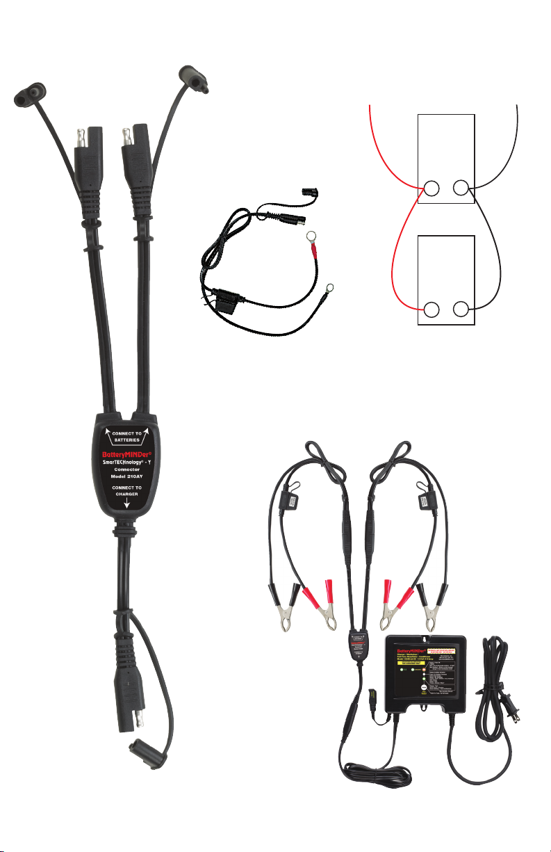
MULTI -BAT TERY
CONFIGURATION
(2 - 24V parallel only)
BatteryMINDer unit
connected to two sets
of BC 2410 Battery
Clips via 210AY
Y-Connector with
SmarTECHnology*
210AY
Y-Connector with
SmarTECHnology*
*Accessories optional
RTA 2410 Ring
Terminal Assembly
(can be used
in place or in
conjunction with
the BC 2410)
24V
+–
24V
+–
TO CHARGER +
TO CHARGER –

BatteryMINDer® Aviation-Adjusted Models 24041-AA-S2, S3 & S5
Rev. B-062613 Page 20 P/N VDC24041-AA-Sx-MNL
TROUBLESHOOTING GUIDE
PROBLEM POSSIBLE CAUSE SOLUTION
Power ON indicator does
not light after being
plugged into AC for 30
seconds.
AC outlet is dead.
Plug in a lamp or other appliance to
check for voltage. If controlled by
a wall switch, be sure switch is on
and try to prevent accidental shut
off while charger is working.
ERROR indicator lights
RED solid.
Output lead connections
to battery may be
reversed.
Switch (reverse) connections at
battery.
Battery voltage
<6 volts.
Battery may be damaged and should
not be recharged. Allow battery to
“recover” by letting it “rest” without
a load.
Battery was just recently
removed from a load
(lights, electronic
equipment) or not
used for extended time
without a charger-
maintainer.
If battery is healthy and just deeply
discharged it should recover
its voltage (rise above 6 volts)
sufficiently to allow charger to begin
an attempt to fully recharge it.
Battery has “rested” and
still cannot be recovered
– recharged.
Battery should be safely discarded
– recycled.
ERROR Indicator lights
RED blinking.
Battery(s) may be weak,
heavily sulfated, or too
large to fully charge
before unit times out.
Allow battery to remain in
Maintenance-Float mode for 72 hours
or more and then attempt to recharge
again.
Battery may be so large
it may require a second
full recharge.
Reboot unit by unplugging from
A.C. electrical outlet, disconnect
from battery so there will be no
electrical power going to the unit
from either direction, wait 10
seconds, connect to battery first
then plug into A.C. outlet
Battery Condition
Indicator lights YELLOW
(Before battery has been
completely charged).
Battery can be weak
due to sulfation, self
discharge or was very
deeply discharged.
Attempt a full recharge and recheck
after completion. If still YELLOW,
follow next procedure (“After battery
has been completely charged.”)
Con’t. on next page
This manual suits for next models
3
Table of contents
Other BatteryMINDer Batteries Charger manuals

BatteryMINDer
BatteryMINDer SCC1224 User manual

BatteryMINDer
BatteryMINDer 24041-AA-S3 User manual

BatteryMINDer
BatteryMINDer DS24041-AA-S5 Specifications

BatteryMINDer
BatteryMINDer 1215C User manual

BatteryMINDer
BatteryMINDer BatteryMINDer 36271 User manual

BatteryMINDer
BatteryMINDer Plus 12117TC User manual

BatteryMINDer
BatteryMINDer 483CEC1 User manual

BatteryMINDer
BatteryMINDer BatteryMINDer 36271 User manual

BatteryMINDer
BatteryMINDer SCC180 User manual

BatteryMINDer
BatteryMINDer E12248-AA-S2 User manual


