BatteryMINDer 24041-AA-S3 User manual
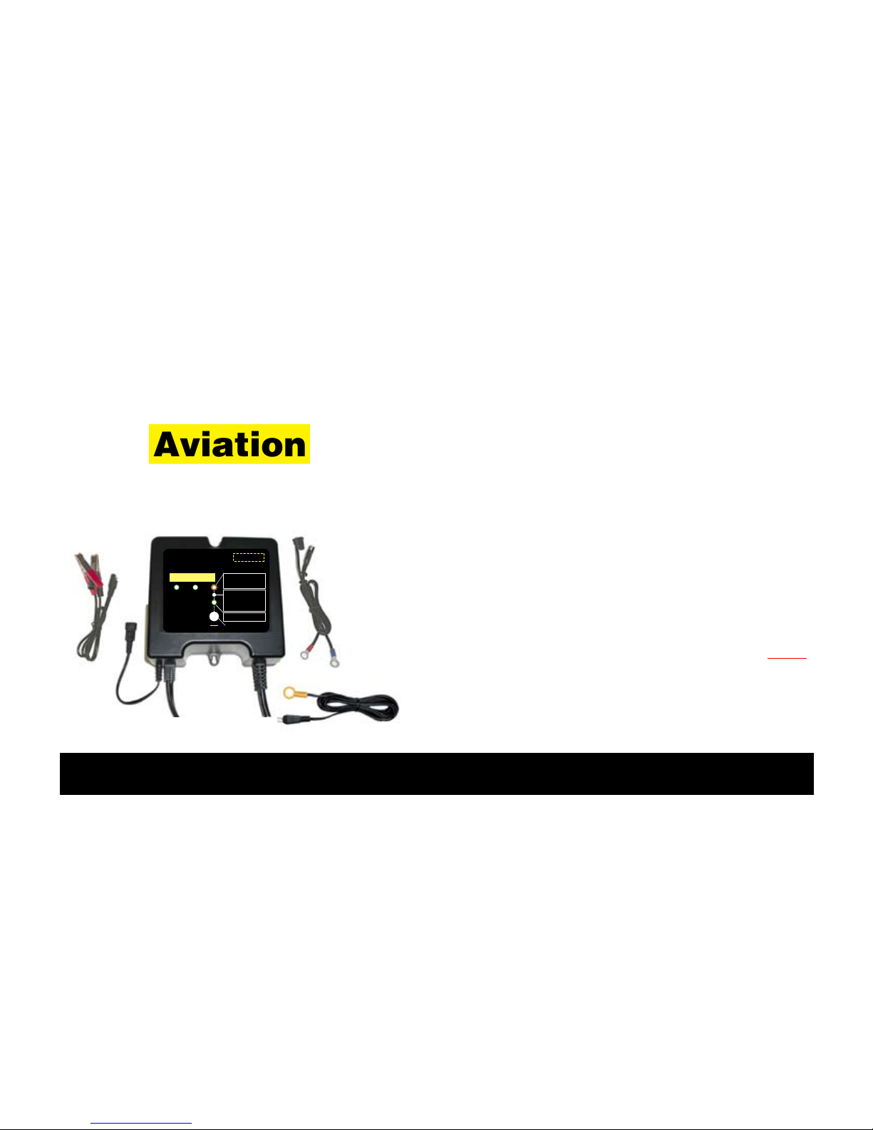
Rev. A-021009 P/N VDC24041AA-S3-MNL
BatteryMINDer® Model 24041-AA-S3
Page 1
INSTRUCTION MANUAL
BatteryMINDer®
Model 24041-AA-S3*
Gill LT Series 24-Volt
Aviation Charger / Maintainer /
Desulphator-Conditioner
VDC Electronics, Inc.
147 D Woodbury Rd.
Huntington, NY 11743
www.batteryminders.com
READ AND SAVE THESE INSTRUCTIONS
9LL=JQ'#(=J
¸
Charger / Maintainer /
Full Time De-Sulfator - Conditioner
Model 24041-AA-S1 24-Volt @ 4 Amp
4 A
Until
4A Lit Until
Aviation Lit
PRESSPRESSPRESS
MAINTENANCE
MODE ONLY
(HOLD 3 SEC.)
Start / Reset
/ Stop
U.S. Patents: 5783929 & 6078166
VDC Electronics, Inc.
800-379-5579 (ET)
www.vdcelectronics.com
AVIATION
AVIATION-CALIBRATED
AIRCRAFT BATTERY ONLY
FOR LEAD-ACID
GA BATTERY ONLY
Green = Power ON
ERROR:
Red = Polarity Reversed
/ Battery = less than 6-Volts
*
Red (Blinking) = Battery not fully charged -
charger in float-maintenance mode
*
Battery Condition Indication
Power On & Battery Connected
Before Start Charge:
Green = OK - Accepted
Yellow = Weak / Sulfated / Deep Discharge
*
After Charge:
Green = Good
Yellow = Sulfated / Weak
*
Charge - Float
Green (solid) = Charging
Green (blinking) = Float (maintenance)
*
See Instruction Manual
Hold for 5 sec. for full reset
*For use with Gill LT Aircraft Batteries ONLY.
Requires proper installation of Battery Temperature
Sensor (ABS-248 - supplied).
9LL=JQ'#(=J¸
Charger / Maintainer /
Full Time Desulfator - Conditioner
Model 24041-AA-S3 24-Volt @ 4 Amp
4 A
Charge- Float
Green(solid) = Charging
Green(blinking)= Float (maintenance)
*See InstructionManual
PRESS
Stop
VDC Electronics, Inc.
800-379-5579 (ET)
www.batteryminders.com
U.S. Patented & Patent Pending
Gill LT
Series
ONLY
AVIATION-CALIBRATED
GILL LT SERIES ONLY
FOR LEAD-ACID
GA BATTERY ONLY
Green = Power ON
ERROR:
Red = Polarity Reversed
/ Battery = less than 6-Volts*
Red (Blinking) = Battery not fully charged -
charger in float-maintenance mode*
Battery Condition Indication
Power On & Battery Connected
Before Start Charge:
Green = OK - Accepted
Yellow = Weak / Sulfated / Deep Discharge*
After Charge:
Green = Good
Yellow = Sulfated / Weak*
Restart Hold for 5 sec. for full reset
Rev. A-021009 P/N VDC24041AA-S3-MNL

Rev. A-021009 P/N VDC24041AA-S3-MNL
BatteryMINDer® Model 24041-AA-S3
Page 2
TABLE OF CONTENTS
Safety Instructions...................................................................................................................... 3
Preparing To Charge................................................................................................................... 5
Charger Location......................................................................................................................... 5
DC Connection Precautions....................................................................................................... 6
Qualifying Your Battery .............................................................................................................. 8
Testing With A Hot/Cold Calibrated Hydrometer Tester.......................................................... 10
Unit With Call-outs ..................................................................................................................... 12
Simplified Operating Instructions ............................................................................................. 13
LED Indicator Functions ............................................................................................................ 14, 15
Detailed Operation Instructions ................................................................................................ 16
Temperature Sensor ABS-248 (At-the-Battery Sensor).............................................. 17, 21 - 24
Maintaining Multiple Batteries................................................................................................... 25
Battery Configurations .............................................................................................................. 26
Troubleshooting - Model 24041-AA-S3...................................................................................... 27
Detailed Specifications - VDC Model No. 24041-AA-S3......................................................... 29 - 33
Charging Profile.......................................................................................................................... 34
For Repair Or Replacement....................................................................................................... 35
Guarantee And Warranty............................................................................................................ 36

Rev. A-021009 P/N VDC24041AA-S3-MNL
BatteryMINDer® Model 24041-AA-S3
Page 3
Underwriters Laboratories (UL)
REQUIRED SAFETY INSTRUCTIONS
WARNING
TO REDUCE THE RISK OF FIRE,
ELECTRIC SHOCK, OR INJURY TO
PERSON, OBSERVE THE FOLLOWING:
1. Do not expose charger to rain or snow. It is
designed to operate ONLY INDOORS.
2. USE of any attachment not specifically recom-
mended by the battery charger manufacturer for
use with this exact model of charger may result
in risk of fire & electric shock or injury to person.
3. An extension cord should not be used, unless
absolutely necessary. Use of an improper exten-
sion cord could result in fire or electric shock. If
extension cord must be used be sure:
a. Pins on plug of extension cord are the same
number, size, & shape of plug on charger
b. Extension cord is properly wired and in good
condition.
c. Wire size is enough for AC ampere of charger
as specified below: Length of cord, feet (meters)
25 (7.6), 60 (15.2), 100 (30.5), 150 (45.6) AWG
Size #18.
4. Do not use charger if it received a sharp blow,
been dropped, or damaged.
5. Charger contains no serviceable parts. If it fails
for any reason, return to the address shown within
for a free replacement under warranty.
6. To reduce risk of electric shock, unplug charger
from outlet before attempting any cleaning.
7. WARNING - RISK OF EXPLOSIVE GASES.
WHENEVER YOU WORK NEAR A LEAD ACID
BATTERY IT IS DANGEROUS. BATTERIES
GENERATE EXPLOSIVE GASES DURING
NORMAL BATTERY OPERATION. FOR THIS
REASON, IT IS OF UTMOST IMPORTANCE
THAT EACH TIME BEFORE USING YOUR
CHARGER, YOU MUST READ THIS MANUAL
AND FOLLOW THE INSTRUCTIONS EXACTLY.

Rev. A-021009 P/N VDC24041AA-S3-MNL
BatteryMINDer® Model 24041-AA-S3
Page 4
To reduce risk of battery explosion, follow these
instructions and those published by the battery
manufacturer and the manufacturer of any equip-
ment you plan to use in the vicinity of the battery.
Review cautionary markings on the products and
the engine.
8. PERSONAL PRECAUTIONS when working with
or near a lead acid battery.
a. Someone should be able to hear your voice or
close enough to aid you when working near a lead
acid battery.
b. Have fresh water and soap nearby case battery
acid contact skin, clothing, or eyes. Wear com-
plete eye protection and clothing protection. Avoid
touching eyes while working near battery.
c. If battery acid does contact skin or clothing,
wash immediately with soap and water. If acid
entered the eye, immediately ood the eye with
running water for at least 10 minutes and get help
immediately.
d. NEVER smoke or allow a spark of ame near
battery or engine.
e. Be extra cautious to reduce risk of dropping a
metal tool onto battery. It might spark or short cir-
cuit battery or other electrical part that may cause
an explosion.
f. Remove personal metal items such as rings,
bracelets, necklaces, and watches when work-
ing with a lead acid battery. A lead acid battery
can produce a short circuit current high enough to
weld a ring or the like to metal, causing a severe
burn.
g. Charger is designed to be used for recharging
Gill LT Series 24V lead acid batteries ONLY. Never
use it to power a low voltage electrical system, or
for attempting to recharge dry cell batteries that
are commonly used in house holds. These batter-
ies may explode and cause injury to persons and
damage property

Rev. A-021009 P/N VDC24041AA-S3-MNL
BatteryMINDer® Model 24041-AA-S3
Page 5
NEVER CHARGE A FROZEN BATTERY OR
ONE AT A TEMPERATURE ABOVE 123° F.
PREPARING TO CHARGE
a. Remove battery from equipment to charge.
Always remove ground terminal rst. Turn off all
accessories in the aircraft, so as not to cause an
arc.
b. Be sure area around battery is well ventilated
while battery is being charged. Force gas vapors
away by using a piece of non-metallic material as
a fan.
c. Clean battery terminals. Be careful to keep cor-
rosion from contacting eyes.
d. Study all battery manufacturer’s specic
instructions such as recommended charge rates.
e. Determine condition of battery, by referring
to instructions herein, before ever attempting to
charge or desulfate any / all batteries.
CHARGER LOCATION
a. Make sure charger is as far away from battery
as output cables permit.
b. Never place charger directly above battery
being charged; gases from battery will corrode
and damage charger.
c. Never allow battery acid to drip on charger
when reading specic gravity or lling.
d. Do not operate charger in a closed-in area or
restrict ventilation in any way.
e. Do not set battery on top of charger.

Rev. A-021009 P/N VDC24041AA-S3-MNL
BatteryMINDer® Model 24041-AA-S3
Page 6
DC CONNECTION PRECAUTIONS
Note: Steps to be done in a well-ventilated area
away from aircraft.
a. Connect and disconnect DC output clips from
battery only after removing charger power cord
from outlet.
b. Attach clips to battery posts and twist or rock
back and forth several times to make good con-
tact. This tends to keep clips from slipping off ter-
minals and reduces risk of sparking.

Rev. A-021009 P/N VDC24041AA-S3-MNL
BatteryMINDer® Model 24041-AA-S3
Page 7
A SPARK NEAR THE BATTERY MAY CAUSE
BATTERY EXPLOSION. TO REDUCE RISK OF
A SPARK NEAR BATTERY:
a. Check polarity of battery posts. POSITIVE
(POS,P,+) usually has a large diameter than
NEGATIVE (NEG, N, -) battery post.
b. Connect (RED) charger clip to (POS+) post of
battery.
c. Position yourself and free end of cable as
far away from battery as possible, then connect
NEGATIVE (BLACK) charger clip to free end of
cable.
d. Do not face battery when making final con-
nections.
e. When disconnecting charger, always do so in
reverse sequence of connecting procedure and
break first connection while as far away from bat-
tery as practical. Do not attempt to permanent-
ly install charger not specifically designed-
approved for permanent installation, espe-
cially in a wet high moisture environment.

Rev. A-021009 P/N VDC24041AA-S3-MNL
BatteryMINDer® Model 24041-AA-S3
Page 8
QUALIFYING YOUR BATTERY:
Preliminary Requirements
NOTE: The BatteryMINDer has no electrical
output unless it is connected to a healthy
battery. Testing the BatteryMINDer with a volt
or an Amp meter without the unit being con-
nected across a good battery will result in a false
reading. If you experience any problems, or are
not sure of how to properly use or connect your
BatteryMINDer, please e-mail our technical sup-
port at:
free technical support line 800-379-5579 x201
(Eastern Time). Be certain to leave your phone
number with the area code, time zone and
the best time to call.
To gain the best result from your new charger and
to maximize the life and performance of your bat-
teries we strongly recommend you qualify (test)
your batteries before attempting to either charge-
maintain or desulfate them. Remember, even if
you just purchased a “new” battery it may have
been subjected to conditions that have caused
“sulfation” such as high temperature storage
(>=80°).
NOTE: If your battery is new and you are
certain it was not subject to conditions that
could have caused sulfation*, even before
you purchased it, then you can disregard our
recommendations for qualifying / testing your
battery, before using the BatteryMINDer.
* Such as high temperature storage (=/> 80°F)
and/or allowed to self-discharge to 24.8 Volts or
lower.

Rev. A-021009 P/N VDC24041AA-S3-MNL
BatteryMINDer® Model 24041-AA-S3
Page 9
USE A DIGITAL VOLTMETER ONLY:
1. Recharge the battery with the
BatteryMINDer to ensure it is as completely
charged as possible, before you determine its
condition. Allow battery to “rest” (see pg. 9) over-
night for a minimum of 12 hours before testing
with a digital voltmeter only.
Failure to test a “rested” (see pg. 9) battery will
cause false readings. Be certain to read and
understand all safety related instructions (pages 3
to 7) before proceeding further.
2. Measure battery’s voltage, without any load
attached. If the voltage is less than 25.2 volts
(Typically 75% of charge) the battery may be too
heavily sulfated to be fully recoverable. If voltage
is 25.2-V or higher full recovery can be expected,
given sufficient time (average 1-2 weeks for batter-
ies that are heavily sulfated).
3. Connect the BatteryMINDer to the battery.
4. Charge battery to its maximum level. Allow
battery to remain for a minimum of 72 hours
before retesting. If improvement is seen, continue
until battery voltage reaches full capacity level or
no further increase is seen.

Rev. A-021009 P/N VDC24041AA-S3-MNL
BatteryMINDer® Model 24041-AA-S3
Page 10
Before proceeding further you must be thor-
oughly familiar with the safety and operating
instructions.
1. Recharge the battery with the BatteryMINDer
to ensure that it is completely charged before you
determine its condition. Allow battery to “rest”*
overnight for a minimum of 12 hours before test-
ing with a digital type voltmeter only.
* “RESTED” = a battery that has been as fully
charged as possible, using a 3 stage charger
(model 24041-AA-S3) and left disconnected
from charger or any type load for a minimum
of 12 hours.
2. If the BatteryMINDer battery condition LED
lights (YELLOW) after 72 hours (single battery
- battery voltage ±/≤25.2), your battery may be
too far gone to be fully desulfated. Reconnect
battery to your BatteryMINDer. Allow battery to
remain in maintenance mode for a minimum of 72
hours, before re-test. If you see an increase in the
voltage, indicating that there is an improvement
in the battery’s condition, continue desulfating
for an additional 72 hours and retest the battery.
Continue this process until voltage readings no
longer increase.
Note: Do not expect to completely eliminate
sulfate in a few days. Long established sul-
fate will require several weeks or longer to
be fully dissolved. Be patient and you will be
rewarded with a “sulfate-free” battery.
OCV - “Rested”
Voltage
Full Capacity
Percentage
25.8 - 26.2 Volts 100%
25.2 - 25.8 Volts 75%
24.8 - 25.2 Volts 50%
24.4 - 24.8 Volts 25%
24.0 - 24.4 Volts 0%
<22 Volts
= shorted
OCV=Open Circuit No Load Voltage
TABLE 1

Rev. A-021009 P/N VDC24041AA-S3-MNL
BatteryMINDer® Model 24041-AA-S3
Page 11
Your Notes:

Rev. A-021009 P/N VDC24041AA-S3-MNL
BatteryMINDer® Model 24041-AA-S3
Page 12
1) Battery clip cordset w/ qwik connect plug (pgs.13, 16)
2) Ring terminal cordset w/ qwik connect plug (pgs. 13, 16)
3) Mounting tabs
4) Input power cordset (pg. 13, 17)
5) Output cord w/ qwik connect plug (pg. 13, 16)
6) Temperature sensor input connector (pg. 17)
7) Stop/Restart selection button (pgs. 13, 17)
8) LED indicators for power, connection, fault, battery
condition, charge status (pgs.13-15, 17–20, 31)
9) Temperature sensor with extension cord and ring
terminal (pg. 17, 21 - 23, 32)
1
8
7
7
64
5
3
2
9
9LL=JQ'#(=J¸
Charger / Maintainer /
Full Time Desulfator - Conditioner
Model 24041-AA-S3 24-Volt @ 4 Amp
4 A
Charge - Float
Green (solid) = Charging
Green (blinking) = Float (maintenance)
*See Instruction Manual
PRESS
Stop
VDC Electronics, Inc.
800-379-5579 (ET)
www.batteryminders.com
U.S. Patented & Patent Pending
Gill LT
Series
ONLY
AVIATION-CALIBRATED
GILL LT SERIES ONLY
FOR LEAD-ACID
GA BATTERY ONLY
Green = Power ON
ERROR:
Red = Polarity Reversed
/ Battery = less than 6-Volts*
Red (Blinking) = Battery not fully charged -
charger in float-maintenance mode*
Battery Condition Indication
Power On & Battery Connected
Before Start Charge:
Green = OK - Accepted
Yellow = Weak / Sulfated / Deep Discharge*
After Charge:
Green = Good
Yellow = Sulfated / Weak*
Restart Hold for 5 sec. for full reset

Rev. A-021009 P/N VDC24041AA-S3-MNL
BatteryMINDer® Model 24041-AA-S3
Page 13
Simplified Operating Instructions
(Read and thoroughly understand ALL SAFETY Instructions on pages (3-7) and Qualifying
Your Battery pages 8-11, BEFORE proceeding further.
1. Attach a battery connector assembly (supplied) to output cordset of charger, either the clips or ring
terminal assembly, - NEVER BOTH at same time.
2. Attach output to battery terminals-RED band =Positive + BLACK band = Negative.
2-a: Attach temperature sensor ABS-248 to battery and then to charger*.
3. Plug AC power cord into 120 Vac electrical outlet. Observe REVERSED Polarity LED indicator. If lit
RED, reverse battery connector attachments on battery.
4. Observe GREEN LED indicator labeled Charge-Float = Solid when charging, Blinking when main-
taining battery(s). Charger will automatically start within 30 seconds or less.
5. Observe Battery Connected - Error Indicator, LED Must be lit GREEN.**
IF IN DOUBT REGARDING ANY OF THE ABOVE, REFER TO FULL INSTRUCTIONS
* See detailed instructions for need and method of properly connecting sensor to battery, pgs. 21 - 24.
** See full instructions if not lit GREEN.

Rev. A-021009 P/N VDC24041AA-S3-MNL
BatteryMINDer® Model 24041-AA-S3
Page 14
Battery Condition Indication
Battery connected BEFORE full charge: Vb<22V YELLOW
Vb>22V GREEN
If Stop/Restart Button in Pressed during charging mode STOPS CHARGING. PRESS AGAIN TO RESTART.
Battery Sulfation check (AFTER FULL CHARGE & “RESTED”
[See p.9]): Vb<25.8V
Vb>25.8V
YELLOW
GREEN
LED Status - (Battery Connected / Error and Charge LEDs) CONNECTED / ERROR CHARGE - FLOAT
GREEN RED GREEN
A.C. power disconnected, battery connected correctly OFF OFF
A.C. power connected, battery connected GREEN OFF
A.C. power connected, battery connected (press start button) GREEN ON
At Soft Start mode, Bulk charge mode, Absorption mode GREEN ON
In Sulfate check mode Float charge mode GREEN FLASH
A.C. power connected Reversed Battery Polarity RED ON OFF
A.C. power connected, charger output Clip shorted RED ON OFF
A.C. power connected, battery voltage is less than 3V RED ON OFF
Timed-out when in SoftStart or Bulk mode RED FLASH OFF
Timed-out when in Absorption mode & Forced to Float mode RED FLASH FLASH
Battery Fault / Battery Weak RED FLASH OFF
LED INDICATOR FUNCTIONS -- Tables 3 (top) and 4 A&B (bottom)

Rev. A-021009 P/N VDC24041AA-S3-MNL
BatteryMINDer® Model 24041-AA-S3
Page 15
9LL=JQ'#(=J¸
Charger / Maintainer /
Full Time Desulfator - Conditioner
Model 24041-AA-S3 24-Volt @ 4 Amp
4 A
Charge - Float
Green (solid) = Charging
Green (blinking) = Float (maintenance)
*See Instruction Manual
PRESS
Stop
VDC Electronics, Inc.
800-379-5579 (ET)
www.batteryminders.com
U.S. Patented & Patent Pending
Gill LT
Series
ONLY
AVIATION-CALIBRATED
GILL LT SERIES ONLY
FOR LEAD-ACID
GA BATTERY ONLY
Green = Power ON
ERROR:
Red = Polarity Reversed
/ Battery = less than 6-Volts*
Red (Blinking) = Battery not fully charged -
charger in float-maintenance mode*
Battery Condition Indication
Power On & Battery Connected
Before Start Charge:
Green = OK - Accepted
Yellow = Weak / Sulfated / Deep Discharge*
After Charge:
Green = Good
Yellow = Sulfated / Weak*
Restart Hold for 5 sec. for full reset
GREEN
AVIATION
ON
GREEN
4A
ON
LED INDICATOR FUNCTIONS
LED indicators refer to charger label at right
TABLE 5
TABLE 6

Rev. A-021009 P/N VDC24041AA-S3-MNL
BatteryMINDer® Model 24041-AA-S3
Page 16
Detailed Operation Instructions
Model 24041-AA-S3
After carefully reading and understanding the
Safety Instructions contained in this manual
(pages 3 to 7) and having evaluated your battery
as described in Qualifying Your Battery (pages 8 to
11) you are properly prepared to begin using your
charger.
1. Attach output cord of charger to either the
Battery Clip(s) Assembly (BCA) (supplied) or the
Ring Terminal Assembly (RTA) (supplied) depend-
ing on your preference. However never use both
assemblies at the same time for any reason what-
soever.
Never use either of these assemblies on any
other charger or for any other purpose such
as improvised “jumper cables”, etc.
Using the RTA on batteries remaining in their nor-
mal use location (in same place they are regularly
installed will normally prove the safest and most
convenient. If you have several applications you
may wish to purchase additional Ring Terminal
Assemblies (RTA) available from your dealer or
VDC Electronics, Inc. directly.
Note: this assembly contains a 10 Amp auto-
motive type fuse and is replaceable should
for any reason it were to blow. Never replace
this fuse with any type whose rating is higher
than 10 Amps, as seriously harmful results
may occur.
2. Identify the positive and negative posts or
connections on your battery, usually clearly des-
ignated with the polarity markings of + (positive)
and – (negative). If you have previously installed
the RTA referred to in 1. above, you need only to
press the connector plug of the charger’s output
cord into the mating plug of the RTA. Push firmly
and do not leave any space between them.

Rev. A-021009 P/N VDC24041AA-S3-MNL
BatteryMINDer® Model 24041-AA-S3
Page 17
Correct polarity and a good connection will be
your reward. Attach the BCA to the proper battery
posts, clamps or screw terminals, depending on
type of battery.
Note: Temperature Compensation Sensor
Assembly (Part# ABS-248). See pages 21 - 24
for full detailed instructions.
3. Plug the unit’s Power cord into a standard
– grounded 120 Vac electrical outlet. The Battery
Connected LED Indicator will light GREEN. If it
does not light GREEN check the outlet to be
sure it is functioning. In addition, be sure if outlet
is controlled by a switch, no one will accidentally
shut off the power to the outlet. Check for cor-
rect polarity = (no ERROR RED LED Indicator). If
ERROR Indicator is lit, reverse the charger’s out-
put connections to the battery.
4. Charger will automatically start within 30 sec-
onds or less. The Charge – Float LED Indicator
will light GREEN. The charger will now begin
charging by first checking the battery to determine
its voltage and ability to accept a charge. Should
the battery not have a normal fully discharged
voltage (21.0-V minimum) the unit will begin
charging in the “Soft-Start” mode to determine if
the battery can be safely charged. If it cannot, the
Battery Connected – Error LED will flash RED and
charging will be stopped. Battery should be care-
fully checked under a load by a qualified person
before further attempting to charge it.

Rev. A-021009 P/N VDC24041AA-S3-MNL
BatteryMINDer® Model 24041-AA-S3
Page 18
Your Notes:

Rev. A-021009 P/N VDC24041AA-S3-MNL
BatteryMINDer® Model 24041-AA-S3
Page 19
Note: If the battery does not have a mini-
mum no load OCV (Open Circuit Voltage)
of 6 volts, the ERROR LED will light
RED and charger will reject battery.
No further effort should be made to charge this bat-
tery with this charger or any charger. Discard this
battery, unless it has just been subjected to a long
period of continuous discharge under a load such
as can occur with leaving lights on or cranking an
engine excessively. Allow such a battery to “Rest”
for several hours (overnight if possible) before
determining if it is defective. Be very suspicious of
any 24-V battery that does not have at least 22-
Volts (OCV) before it is recharged. It may well be
seriously damaged and unsafe for any type of use
or recharge. The unit’s Battery Condition Indication
LED will help you determine if battery is less than 22-
Volts (YELLOW)) or greater than 22-Volts (GREEN)
7. After battery has been fully charged, the GREEN
Charge-Float LED Indicator will begin blinking.
It will continue to blink indefinitely, unless unit is
disconnected from battery or Stop/Restart button
is pressed. Should battery be unable to be fully
charged, the LED will not blink and the RED Error
LED will blink. Battery may not be able to be fully
charged, may be too large or too deeply discharged
to be fully charged in the normal time allowed by
charger. If you are certain battery is not defective,
having read and understood completely all of the
above concerns and conditions, proceed to restart
the charger by pressing and holding the Stop/Restart
button for approx. 5 seconds until all LEDs Flash.
This allows charger to begin charging battery again.

Rev. A-021009 P/N VDC24041AA-S3-MNL
BatteryMINDer® Model 24041-AA-S3
Page 20
If battery is not defective it should be able to be
fully charged after being restarted. After sufficient
time has lapsed the GREEN charge LED Indicator
will blink confirming when / if battery is now fully
charged.
Note: If attempting to charge more than one
battery at a time it is very likely the char-
ger will need to be restarted as described in
order to completely charge multiple batter-
ies. We do not recommend charging more
than one battery at a time without confirm-
ing the individual condition of each battery
and monitoring the charging and batteries
closely. A better solution is to charge each
battery separately using your model 24041-
AA-S3 BatteryMINDer and then connect them
together, if desired for long term mainte-
nance-float charging. We suggest your read-
ing the detailed specifications on pages (21
- 26), including the additional LED indicator
functions (pgs. (14-15) not already covered
above.
After carefully reading these instructions and
Troubleshooting (pgs. 27 - 28) sections, should
you still have questions, please e-mail our techni-
cal support department at:
Allow up to 3 business days for a detailed
response to your questions. Always identify the
model number of the product and revision letter of
this manual contained on this page below. Without
this information we may not be able to assist you
correctly.
If your questions have already been answered in
this manual you can expect a response referring
you back to this manual and the specific page(s).
Table of contents
Other BatteryMINDer Batteries Charger manuals

BatteryMINDer
BatteryMINDer 128CEC1 User manual

BatteryMINDer
BatteryMINDer 483CEC1 User manual

BatteryMINDer
BatteryMINDer 24041-AA Series User manual

BatteryMINDer
BatteryMINDer E12248-AA-S2 User manual

BatteryMINDer
BatteryMINDer DS24041-AA-S5 Specifications

BatteryMINDer
BatteryMINDer BatteryMINDer 36271 User manual

BatteryMINDer
BatteryMINDer Plus 12117TC User manual

BatteryMINDer
BatteryMINDer SCC1224 User manual

BatteryMINDer
BatteryMINDer 24041 User manual

BatteryMINDer
BatteryMINDer BatteryMINDer 36271 User manual