BatteryMINDer E12248-AA-S2 User manual

Rev. A-021210 Page 1 P/N VDC E12248-S2-MNL
BatteryMINDer® E12248-AA-S2
INSTRUCTION MANUAL
Rev. A-021210 P/N VDC E12248AA-S2-MNL
VDC Electronics, Inc.
147 D Woodbury Rd.
Huntington, NY 11743 U.S.A.
www.batteryminders.com
*For use with Aviation Type 12-V Batteries ONLY. Requires proper
installation of Battery Temperature Sensor (ABS-248 - supplied). Not
for use with Gill LT Series or Odyssey Aircraft Batteries.
READ AND SAVE THESE
INSTRUCTIONS
BatteryMINDer®
Model
E
12248-AA-S2*
Aviation Charger /
Maintainer /
Desulfator-Conditioner
See Page 13 for Simplied Operating Instructions

Rev. A-021210 Page 2 P/N VDC E12248-S2-MNL
BatteryMINDer® E12248-AA-S2
TABLE OF CONTENTS
Safety Instructions............................................................3
Preparing To Charge...........................................................5
Charger Location...............................................................5
DC Connection Precautions..................................................6
Qualifying Your Battery: ......................................................8
Testing A Filler Cap Or Manifold-type Lead Acid Battery................8
Testing With A Hot/Cold Calibrated Hydrometer Tester.................10
Testing A Sealed, AGM Or Flooded (wet-cell) Lead Acid Battery ....10
Unit With Call-outs ..........................................................12
Simplified Operating Instructions .........................................13
LED Indicator Functions ...............................................14, 15
Detailed Operation Instructions ...........................................16
Temperature Sensor ABS-248 (At-the-Battery Sensor).......17, 21 - 24
Maintaining Multiple Batteries.............................................25
Battery Configurations .....................................................26
Troubleshooting - Model E12248-AA-S2..................................27
Detailed Specifications - VDC Model No. E12248-AA-S2.........29 - 33
Charging Profile..............................................................34
For Repair Or Replacement..................................................35
Warranty........................................................................36

Rev. A-021210 Page 3 P/N VDC E12248-S2-MNL
BatteryMINDer® E12248-AA-S2
REQUIRED SAFETY INSTRUCTIONS
WARNING
TO REDUCE THE RISK OF FIRE,
ELECTRIC SHOCK, OR INJURY TO
PERSON, OBSERVE THE FOLLOWING:
1. Do not expose charger to rain or snow. It is designed to oper-
ate ONLY INDOORS.
2. USE of any attachment not specifically recommended by the
battery charger manufacturer for use with this exact model of
charger may result in risk of fire & electric shock or injury to per-
son. 3. An extension cord should not be used, unless absolutely
necessary. Use of an improper extension cord could result in fire
or electric shock. If extension cord must be used be sure:
a. Pins on plug of extension cord are the same number, size, &
shape of plug on charger
b. Extension cord is properly wired and in good condition.
c. Wire size is enough for AC ampere of charger as specified
below: Length of cord, feet (meters) 25 (7.6), 60 (15.2), 100
(30.5), 150 (45.6) AWG Size #18.
4. Do not use charger if it received a sharp blow, been dropped,
or damaged.
5. Charger contains no serviceable parts. If it fails for any reason,
return to the address shown within for a free replacement under
warranty.
6. To reduce risk of electric shock, unplug charger from outlet
before attempting any cleaning.
7. WARNING - RISK OF EXPLOSIVE GASES.WHENEVER
YOU WORK NEAR A LEAD ACID BATTERY IT IS
DANGEROUS. BATTERIES GENERATE EXPLOSIVE GASES
DURING NORMAL BATTERY OPERATION. FOR THIS
REASON, IT IS OF UTMOST IMPORTANCE THAT EACH
TIME BEFORE USING YOUR CHARGER, YOU MUST
READ THIS MANUAL AND FOLLOW THE INSTRUCTIONS
EXACTLY.

Rev. A-021210 Page 4 P/N VDC E12248-S2-MNL
BatteryMINDer® E12248-AA-S2
To reduce risk of battery explosion, follow these instructions and
those published by the battery manufacturer and the manufactur-
er of any equipment you plan to use in the vicinity of the battery.
Review cautionary markings on the products and the engine.
8. PERSONAL PRECAUTIONS when working with or near a lead
acid battery.
a. Someone should be able to hear your voice or close enough
to aid you when working near a lead acid battery.
b. Have fresh water and soap nearby case battery acid contact
skin, clothing, or eyes. Wear complete eye protection and clothing
protection. Avoid touching eyes while working near battery.
c. If battery acid does contact skin or clothing, wash immediately
with soap and water. If acid entered the eye, immediately ood
the eye with running water for at least 10 minutes and get help
immediately.
d. NEVER smoke or allow a spark of ame near battery or en-
gine.
e. Be extra cautious to reduce risk of dropping a metal tool onto
battery. It might spark or short circuit battery or other electrical
part that may cause an explosion.
f. Remove personal metal items such as rings, bracelets, neck-
laces, and watches when working with a lead acid battery. A lead
acid battery can produce a short circuit current high enough to
weld a ring or the like to metal, causing a severe burn.
g. Charger is designed to be used for recharging lead acid bat-
teries ONLY. Never use it to power a low voltage electrical system,
or for attempting to recharge dry cell batteries that are commonly
used in house holds. These batteries may explode and cause
injury to persons and damage property

Rev. A-021210 Page 5 P/N VDC E12248-S2-MNL
BatteryMINDer® E12248-AA-S2
NEVER CHARGE A FROZEN BATTERY OR ONE AT A
TEMPERATURE ABOVE 123° F.
PREPARING TO CHARGE
a. Turn off all accessories in the aircraft, so as not to cause an
arc. If battery manufacturer requires battery to be removed from
aircraft before charging, always remove ground wire rst.
b. Be sure area around battery is well ventilated while battery is
being charged. Force gas vapors away by using a piece of non-
metallic material as a fan.
c. Clean battery terminals. Be careful to keep corrosion from
contacting eyes.
d. Add distilled water to each cell until battery acid reaches level
specied by the manufacturer. This helps purge excessive gas
from cells. Do not overll. For a battery without caps, follow man-
ufacturer’s recharging instructions.
e. Study all battery manufacturer’s specic instructions such as
removing cell caps while charging and recommended charge
rates.
f. Determine condition of battery, by referring to instructions
herein, before ever attempting to charge or desulfate any / all
batteries.
CHARGER LOCATION
a. Make sure charger is as far away from battery as output
cables permit.
b. Never place charger directly above battery being charged;
gases from battery will corrode and damage charger.
c. Never allow battery acid to drip on charger when reading spe-
cic gravity or lling.
d. Do not operate charger in a closed-in area or restrict ventila-
tion in any way.
e. Do not set battery on top of charger.

Rev. A-021210 Page 6 P/N VDC E12248-S2-MNL
BatteryMINDer® E12248-AA-S2
DC CONNECTION PRECAUTIONS
Note: Steps to be done in a well-ventilated area away from
aircraft.
a. Connect and disconnect DC output clips from battery only
after removing charger power cord from outlet.
b. Attach clips to battery posts and twist or rock back and forth
several times to make good contact. This tends to keep clips
from slipping off terminals and reduces risk of sparking.

Rev. A-021210 Page 7 P/N VDC E12248-S2-MNL
BatteryMINDer® E12248-AA-S2
A SPARK NEAR THE BATTERY MAY CAUSE BATTERY
EXPLOSION. TO REDUCE RISK OF A SPARK NEAR
BATTERY:
a. Check polarity of battery posts. POSITIVE (POS,P,+) usually
has a large diameter than NEGATIVE (NEG, N, -) battery post.
b. Connect (RED) charger clip to (POS+) post of battery.
c. Position yourself and free end of cable as far away from bat-
tery as possible, then connect NEGATIVE (BLACK) charger clip
to free end of cable.
d. Do not face battery when making final connections.
e. When disconnecting charger, always do so in reverse
sequence of connecting procedure and break first connection
while as far away from battery as practical. Do not attempt
to permanently install charger not specifically designed-
approved for permanent installation, especially in a wet
high moisture environment.

Rev. A-021210 Page 8 P/N VDC E12248-S2-MNL
BatteryMINDer® E12248-AA-S2
QUALIFYING YOUR BATTERY:
Preliminary Requirements
NOTE: The BatteryMINDer has no electrical output
unless it is connected to a healthy battery. Testing the
BatteryMINDer with a volt or an Amp meter without the unit
being connected across a good battery will result in a false read-
ing. If you experience any problems, or are not sure of how to
properly use or connect your BatteryMINDer, please e-mail our
technical support at: techsupport@vdcelectronics.com.
To gain the best result from your new charger and to maximize
the life and performance of your batteries we strongly recom-
mend you qualify (test) your batteries before attempting to either
charge-maintain or desulfate them. Remember, even if you just
purchased a “new” battery it may have been subjected to con-
ditions that have caused “sulfation” such as high temperature
(>=80°).
NOTE: If your battery is new and you are certain it was not
subject to conditions that could have caused sulfation*,
even before you purchased it, then you can disregard our
recommendations for qualifying / testing your battery,
before using the BatteryMINDer.
* Such as high temperature storage (=/> 80°F) and/or allowed to
self-discharge to 12.4 Volts or lower.
Testing a Filler Cap Lead Acid Battery
1. Carefully remove all filler caps from your battery.
2. Check the water-liquid electrolyte level. If the level is low or
has ever been below top of plates, severe lead plate sulfation has
taken place. Significant recharge/reconditioning time is needed
to restore these plates to a condition where the battery can be
expected to function normally.

Rev. A-021210 Page 9 P/N VDC E12248-S2-MNL
BatteryMINDer® E12248-AA-S2
3. Refill each cell with distilled water only to the liquid level
indicator found in each cell. Before proceeding further you
must be thoroughly familiar with the safety and operating
instructions.
4. Recharge the battery with the BatteryMINDer to ensure that
it is slowly and completely charged before you determine its
condition. Allow battery to “rest”* overnight or momentarily apply
a small load to remove the “surface” charge which creates false
voltage readings.
* “RESTED” = a battery that has been as fully charged as
possible, using a 3 stage charger (model E12248-AA-S2)
and left disconnected from charger or any type load for a
minimum of 12 hours.
5. If the BatteryMINDer battery condition LED lights (YELLOW)
within 72 hours (single battery) or no balls float in one or more
cells, your battery may be too far gone to be fully desulfated.
Reconnect battery to your BatteryMINDer. Allow battery to
remain in maintenance mode for a minimum of 72 hours, before
re-test. Use a hot/cold calibrated hydrometer tester for the
most accurate results (see Table 1) if you see an increase in
the Specific Gravity (SG) or voltage indicating that there is an
improvement in the battery’s condition, continue desulfating
for an additional 72 hours and retest the battery. Continue this
process until the SG or voltage readings no longer increase.
TABLE 1
Temp. Compensated Hydrometer
or 4 ball type
Full Capacity
Percentage
1.270 (4 Balls oating) 100%
1.250 (3 Balls oating) 75%
1.190 (2 Balls oating) 50%
1.150 (1 Balls oating) 25%
1.120 (0 Balls oating)
May denote shorted cell or battery
that has been severely discharged
and may not be recoverable
0%
Specific Gravity – Capacity

Rev. A-021210 Page 10 P/N VDC E12248-S2-MNL
BatteryMINDer® E12248-AA-S2
Testing with a Hot/Cold Calibrated Hydrometer Tester
Read the tester instructions carefully for most accurate readings.
1. When using the tester the first time or after a long period
of non-use, fill the tester with the battery fluid and let it sit for 1/2
hour or longer. This will soak the balls in order to give you more
accurate readings. Failure to do so will give you false readings
indicating a battery that may not be in as good a condition as
you may have thought.
2. After inserting the tester in a cell, gently tap the tester
several times against the inside wall of each cell to dislodge air
bubbles that will cause more balls to float than should. Failure to
do so will yield false readings that indicate a battery that is not
fully desulfated or does not qualify for desulfation.
3. If no balls float in any cell, the cell is shorted. This means
your battery is beyond the point of being properly recharged or
reconditioned-desulfated. Dispose of the battery.
If each cell floats three (3) or more balls (or 1250 on gauge-type),
your battery can be desulfated-reconditioned.
4. Always rinse the tester with fresh water after every use.
Failure to do so will cause false readings.
Testing a Sealed, AGM or Flooded (wet-cell)
Lead Acid Battery
These batteries have no filler caps or manifold-type covers.
Because you cannot gain access to the interior of your battery
you cannot test it with a hydrometer.
USE A DIGITAL VOLTMETER ONLY:
1. Recharge the battery with the BatteryMINDer to ensure it
is as completely charged as possible, before you determine its
condition. Allow battery to “rest” (see pg. 9) overnight for a mini-
mum of 12 hours before testing with a digital voltmeter only.

Rev. A-021210 Page 11 P/N VDC E12248-S2-MNL
BatteryMINDer® E12248-AA-S2
Failure to test a “rested” (see pg. 9) battery will cause false read-
ings. Be certain to read and understand all safety related instruc-
tions (pages 3 to 7) before proceeding further.
2. Measure battery’s voltage, without any load attached. If
the voltage is less than 12.6 volts (Typically 75% of charge) the
battery may be too heavily sulfated to be fully recoverable. If
voltage is 12.6-V or higher full recovery can be expected, given
sufficient time (average 1-2 weeks for batteries that are heavily
sulfated).
3. Connect the BatteryMINDer to the battery.
4. Charge battery to its maximum level. Allow battery to
remain for a minimum of 72 hours before retesting. If improve-
ment is seen, continue until battery voltage reaches full capacity
level or no further increase is seen.
Note: Do not expect to completely eliminate sulfate in a
few days. Long established sulfate will require several
weeks or longer to be fully dissolved. Be patient and you
will be rewarded with a “sulfate-free” battery.
OCV - “Rested”
Voltage
Full Capacity
Percentage
12.9 - 13.1 Volts 100%
12.6 - 12.9 Volts 75%
12.4 - 12.6 Volts 50%
12.2 - 12.4 Volts 25%
12.0 - 12.2 Volts 0%
<11 Volts
= shorted
OCV=Open Circuit No Load Voltage
TABLE 2
Rev. A-021210 Page 12 P/N VDC E12248-S2-MNL
BatteryMINDer® E12248-AA-S2
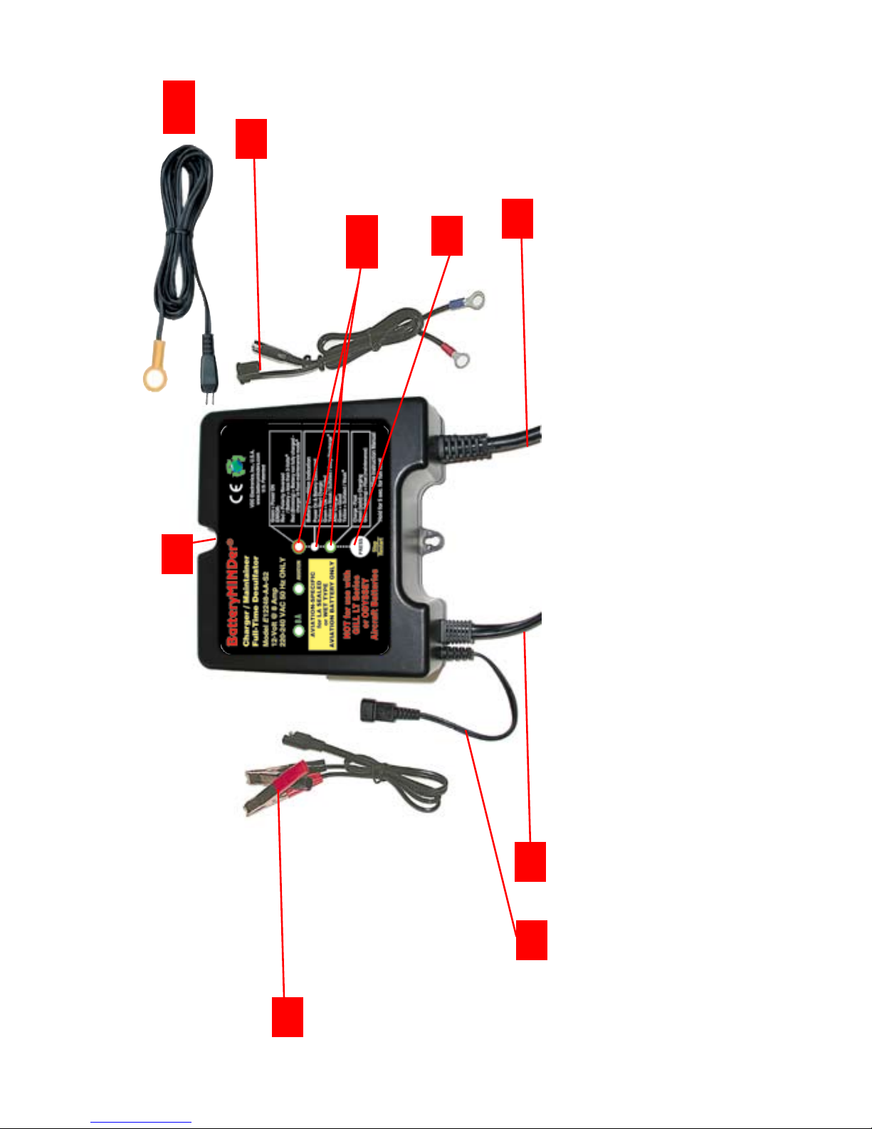
1) Battery clip cordset w/ qwik connect plug (pgs.13, 16)
2) Ring terminal cordset w/ qwik connect plug (pgs. 13, 16)
3) Mounting tabs
4) Input power cordset (pg. 13, 18)
5) Output cord w/ qwik connect plug (pg. 13, 16)
6) Temperature sensor input connector (pg. 17)
7) Stop/Restart selection button
8) LED indicators for power, connection, fault, battery
condition, charge status (pgs.13-15, 18–20, 24)
9) Temperature sensor with cord and ring terminal
(pg. 17, 21 - 23)
1
8
7
64
5
3
2
9

Rev. A-021210 Page 13 P/N VDC E12248-S2-MNL
BatteryMINDer® E12248-AA-S2
Simplified Operating Instructions
(Read and thoroughly understand ALL SAFETY Instructions
on pages (3-7) and Qualifying Your Battery pages 8-11,
BEFORE proceeding further.
1. Attach a battery connector assembly (supplied) to output
cordset of charger, either the clips or ring terminal assembly, -
NEVER BOTH at same time.
2. Attach output to battery terminals-RED band =Positive +
BLACK band = Negative.
2-a: Attach temperature sensor ABS-248 to battery and then to
charger*.
3. Plug AC power cord into 220/240 Vac electrical outlet.
Observe REVERSED Polarity LED indicator. If lit RED, reverse
battery connector attachments on battery.
4. Observe GREEN LED indicator labeled Charge-Float = Solid
when charging, Blinking when maintaining battery(s). Charger will
automatically start within 30 seconds or less.
5. Observe Battery Connected - Error Indicator, LED Must be lit
GREEN.**
IF IN DOUBT REGARDING ANY OF THE ABOVE, REFER TO
FULL INSTRUCTIONS
* See detailed instructions for need and method of properly con-
necting sensor to battery, pgs. 21 - 23.
** See full instructions if not lit GREEN.

Rev. A-021210 Page 14 P/N VDC E12248-S2-MNL
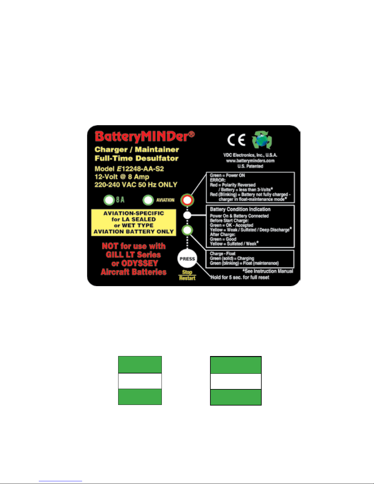
BatteryMINDer® E12248-AA-S2
Battery Condition Indication
Battery connected BEFORE full charge: Vb<11V YELLOW
Vb>11V GREEN
If Stop/Restart Button in Pressed during charging mode STOPS CHARGING. PRESS AGAIN TO
RESTART.
Battery Sulfation check (AFTER FULL CHARGE & “RESTED”
[See p.9]): Vb<12.9V
Vb>12.9V
YELLOW
GREEN
LED Status - (Battery Connected / Error and Charge LEDs) CONNECTED / ERROR CHARGE - FLOAT
GREEN RED GREEN
A.C. power disconnected, battery connected correctly OFF OFF
A.C. power connected, battery connected GREEN OFF
A.C. power connected, battery connected (press Stop/Restart button) GREEN ON
At Soft Start mode, Bulk charge mode, Absorption mode GREEN ON
In Sulfate check mode Float charge mode GREEN FLASH
A.C. power connected Reversed Battery Polarity RED ON OFF
A.C. power connected, charger output Clip shorted RED ON OFF
A.C. power connected, battery voltage is less than 3V RED ON OFF
Timed-out when in SoftStart or Bulk mode RED FLASH OFF
Timed-out when in Absorption mode & Forced to Float mode RED FLASH FLASH
Battery Fault / Battery Weak RED FLASH OFF
LED INDICATOR FUNCTIONS -- Tables 3 (top) and 4 A&B (bottom)
Rev. A-021210 Page 15 P/N VDC E12248-S2-MNL
BatteryMINDer® E12248-AA-S2
GREEN
AVIATION
ON
LED INDICATOR FUNCTIONS
LED indicators refer to charger label at below
GREEN
8A
ON
TABLE 5 TABLE 6

Rev. A-021210 Page 16 P/N VDC E12248-S2-MNL
BatteryMINDer® E12248-AA-S2
Detailed Operation Instructions
Model E12248-AA-S2
After carefully reading and understanding the Safety Instructions
contained in this manual (pages 3 to 7) and having evaluated
your battery as described in Qualifying Your Battery (pages 8 to
11) you are properly prepared to begin using your charger.
1. Attach output cord of charger to either the Battery Clip(s)
Assembly (BCA) (supplied) or the Ring Terminal Assembly (RTA)
(supplied) depending on your preference. However never use
both assemblies at the same time for any reason whatsoever.
Never use either of these assemblies on any other char-
ger or for any other purpose such as improvised “jumper
cables”, etc.
Using the RTA on batteries remaining in their normal use location
(in same place they are regularly installed will normally prove the
safest and most convenient. If you have several applications you
may wish to purchase additional Ring Terminal Assemblies (RTA)
available from your dealer or VDC Electronics, Inc. directly.
Note: this assembly contains a 10 Amp automotive type
fuse and is replaceable should for any reason it were to
blow. Never replace this fuse with any type whose rating
is higher than 10 Amps, as seriously harmful results may
occur.
2. Identify the positive and negative posts or connections on your
battery, usually clearly designated with the polarity markings of +
(positive) and – (negative). If you have previously installed the RTA
referred to in 1. above, you need only to press the connector
plug of the charger’s output cord into the mating plug of the RTA.
Push firmly and do not leave any space between them.

Rev. A-021210 Page 17 P/N VDC E12248-S2-MNL
BatteryMINDer® E12248-AA-S2
Correct polarity and a good connection will be your reward.
Attach the BCA to the proper battery posts, clamps or screw
terminals, depending on type of battery.
Note: Temperature Compensation Sensor Assembly (Part#
ABS-248). See pages 21 - 23 for full detailed instructions.
3. Plug the unit’s Power cord into a standard – grounded
220/240 Vac electrical outlet. The Battery Connected LED
Indicator will light GREEN. If it does not light GREEN check the
outlet to be sure it is functioning. In addition, be sure if outlet is
controlled by a switch, no one will accidentally shut off the power
to the outlet. Check for correct polarity = (no ERROR RED LED
Indicator). If ERROR Indicator is lit, reverse the charger’s output
connections to the battery.
4. Charger will automatically start within 30 seconds or less. The
Charge – Float LED Indicator will light GREEN. The charger will
now begin charging by first checking the battery to determine
its voltage and ability to accept a charge. Should the battery not
have a normal fully discharged voltage (10.5-V minimum) the unit
will begin charging in the “Soft-Start” mode to determine if the
battery can be safely charged. If it cannot, the Battery Connected
– Error LED will flash RED and charging will be stopped. Battery
should be carefully checked under a load by a qualified person
before further attempting to charge it.

Rev. A-021210 Page 18 P/N VDC E12248-S2-MNL
BatteryMINDer® E12248-AA-S2
NOTES:

Rev. A-021210 Page 19 P/N VDC E12248-S2-MNL
BatteryMINDer® E12248-AA-S2
Note: If the battery does not have a minimum no load OCV
(Open Circuit Voltage) of 6 volts, the ERROR LED will light
RED and charger will reject battery.
No further effort should be made to charge this battery with this
charger or any charger. Discard this battery, unless it has just
been subjected to a long period of continuous discharge under
a load such as can occur with leaving lights on or cranking an
engine excessively. Allow such a battery to “Rest” for several
hours (overnight if possible) before determining if it is defective.
Be very suspicious of any 12-V battery that does not have at
least 11-Volts (OCV) before it is recharged. It may well be seri-
ously damaged and unsafe for any type of use or recharge. The
unit’s Battery Condition Indication LED will help you determine if
battery is less than 11-Volts (YELLOW)) or greater than 11-Volts
(GREEN)
7. After battery has been fully charged, the GREEN Charge-Float
LED Indicator will begin blinking. It will continue to blink indefi-
nitely, unless unit is disconnected from battery or Stop/Restart
button is pressed. Should battery be unable to be fully charged,
the LED will not blink and the RED Error LED will blink. Battery
may not be able to be fully charged, may be too large or too
deeply discharged to be fully charged in the normal time allowed
by charger. If you are certain battery is not defective, having read
and understood completely all of the above concerns and condi-
tions, proceed to restart the charger by pressing and holding the
Stop/Restart button for approx. 5 seconds until all LEDs Flash.
This allows charger to begin charging battery again.

Rev. A-021210 Page 20 P/N VDC E12248-S2-MNL
BatteryMINDer® E12248-AA-S2
If battery is not defective it should be able to be fully charged
after being restarted. After sufficient time has lapsed the GREEN
charge LED Indicator will blink confirming when / if battery is now
fully charged.
Note: If attempting to charge more than one battery at a
time it is very likely the charger will need to be restarted as
described in order to completely charge multiple batteries.
We do not recommend charging more than one battery
at a time without confirming the individual condition of
each battery and monitoring the charging and batteries
closely. A better solution is to charge each battery
separately using your BatteryMINDer model E12248-AA-S2
and then connect them together, if desired for long term
maintenance-float charging. We suggest your reading the
detailed specifications on pages (21 - 26), including the
additional LED indicator functions (pgs. (14-15) not already
covered above.
After carefully reading these instructions and Troubleshooting
(pgs. 27 - 28) sections, should you still have questions, please e-
mail our technical support department at:
techsupport@vdcelectronics.com.
Allow up to 3 business days for a detailed response to your
questions. Always identify the model number of the product
and revision letter of this manual contained on this page below.
Without this information we may not be able to assist you
correctly.
If your questions have already been answered in this manual you
can expect a response referring you back to this manual and the
specific page(s).
Table of contents
Other BatteryMINDer Batteries Charger manuals

BatteryMINDer
BatteryMINDer 24041-AA Series User manual

BatteryMINDer
BatteryMINDer SCC1224 User manual

BatteryMINDer
BatteryMINDer Plus 12117TC User manual

BatteryMINDer
BatteryMINDer BatteryMINDer 36271 User manual

BatteryMINDer
BatteryMINDer BatteryMINDer 36271 User manual

BatteryMINDer
BatteryMINDer 24041-AA-S3 User manual

BatteryMINDer
BatteryMINDer 128CEC1 User manual

BatteryMINDer
BatteryMINDer SCC180 User manual

BatteryMINDer
BatteryMINDer DS24041-AA-S5 Specifications

BatteryMINDer
BatteryMINDer 24041 User manual


