BatteryMINDer 24041 User manual
Rev. H-070708 P/N VDC24041-MNL
BatteryMINDer® Model 24041
Page 1
INSTRUCTION MANUAL
BatteryMINDer®
Model 24041*
Charger / Maintainer /
Desulphator-Conditioner
Rev. H-070708 P/N VDC24041-MNL
VDC Electronics, Inc.
147 D Woodbury Rd.
Huntington, NY 11743
www.batteryminders.com
READ AND SAVE THESE INSTRUCTIONS
*NOT for use with
Aviation Type 24-V Batteries
2 A
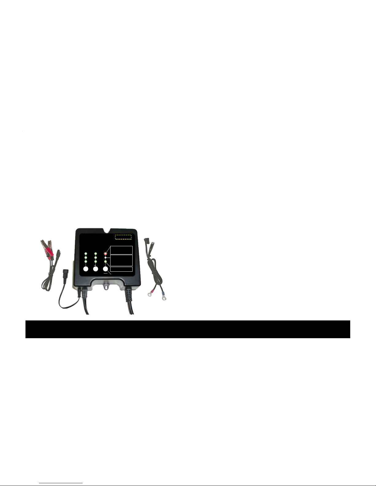
9LL=JQ'#(=J¸
Charger / Maintainer /
Full Time De-Sulfator-Conditioner
24-Volt @ 1/2/4 Amp
Model 24041
4 A
1 A
Select
Charge Rate
Select
Battery Type
Green = Power ON
ERROR:
Red = Polarity Reversed
/ Battery = less than 6-Volts*
Red (Blinking) = Battery not fully charged -
charger in float-maintenance mode*
Charge - Float
Green (solid) = Charging
Green (blinking) = Float (maintenance)
*See Instruction Manual
PRESSPRESSPRESS
Battery Condition Indication
Power On & Battery Connected
Before Start Charge:
Green = OK - Accepted
Yellow = Weak / Sulfated / Deep Discharge*
After Charge:
Green = Good
Yellow = Sulfated / Weak*
MAINTENANCE
(FLOAT)
AGM
GEL
FLOODED
VDC Electronics, Inc.
800-379-5579 (ET)
www.batteryminders.com
U.S. Patented & Patent Pending
Stop
Restart
Hold for 5 sec. for full reset
For Lead-Acid
Batteries ONLY

Rev. H-070708 P/N VDC24041-MNL
BatteryMINDer® Model 24041
Page 2
TABLE OF CONTENTS
Safety Instructions...................................................................................................................... 3
Preparing To Charge................................................................................................................... 5
Charger Location......................................................................................................................... 5
DC Connection Precautions....................................................................................................... 6
Qualifying Your Battery: ............................................................................................................. 8
Testing A Filler Cap Or Manifold-type Lead Acid Battery........................................................ 8
Testing With A Hot/Cold Calibrated Hydrometer Tester.......................................................... 10
Testing A Sealed, Agm Or Gelled-type Lead Acid Battery ..................................................... 10
Unit With Call-outs ..................................................................................................................... 12
Simplified Operating Instructions ............................................................................................. 13
LED Indicator Functions ............................................................................................................ 14, 15
Detailed Operation Instructions ................................................................................................ 16
Temperature Sensor ABS-248 (At-the-Battery Sensor) (OPTIONAL)............................... 17, 21 - 24
Maintaining Multiple Batteries................................................................................................... 25
Battery Configurations .............................................................................................................. 26
Troubleshooting - Model 24041 ................................................................................................ 27
Detailed Specifications - VDC Model No. 24041..................................................................... 29 - 33
Charging Profile.......................................................................................................................... 34
For Repair Or Replacement....................................................................................................... 35
Guarantee And Warranty............................................................................................................ 36

Rev. H-070708 P/N VDC24041-MNL
BatteryMINDer® Model 24041
Page 3
Underwriters Laboratories (UL)
REQUIRED SAFETY INSTRUCTIONS
WARNING
TO REDUCE THE RISK OF FIRE,
ELECTRIC SHOCK, OR INJURY TO
PERSON, OBSERVE THE FOLLOWING:
1. Do not expose charger to rain or snow. It is
designed to operate ONLY INDOORS.
2. USE of any attachment not specifically recom-
mended by the battery charger manufacturer for
use with this exact model of charger may result
in risk of fire & electric shock or injury to person.
3. An extension cord should not be used, unless
absolutely necessary. Use of an improper exten-
sion cord could result in fire or electric shock. If
extension cord must be used be sure:
a. Pins on plug of extension cord are the same
number, size, & shape of plug on charger
b. Extension cord is properly wired and in good
condition.
c. Wire size is enough for AC ampere of charger
as specified below: Length of cord, feet (meters)
25 (7.6), 60 (15.2), 100 (30.5), 150 (45.6) AWG
Size #18.
4. Do not use charger if it received a sharp blow,
been dropped, or damaged.
5. Charger contains no serviceable parts. If it fails
for any reason, return to the address shown within
for a free replacement under warranty.
6. To reduce risk of electric shock, unplug charger
from outlet before attempting any cleaning.
7. WARNING - RISK OF EXPLOSIVE GASES.
WHENEVER YOU WORK NEAR A LEAD ACID
BATTERY IT IS DANGEROUS. BATTERIES
GENERATE EXPLOSIVE GASES DURING
NORMAL BATTERY OPERATION. FOR THIS
REASON, IT IS OF UTMOST IMPORTANCE
THAT EACH TIME BEFORE USING YOUR
CHARGER, YOU MUST READ THIS MANUAL
AND FOLLOW THE INSTRUCTIONS EXACTLY.

Rev. H-070708 P/N VDC24041-MNL
BatteryMINDer® Model 24041
Page 4
To reduce risk of battery explosion, follow these
instructions and those published by the battery
manufacturer and the manufacturer of any equip-
ment you plan to use in the vicinity of the battery.
Review cautionary markings on the products and
the engine.
8. PERSONAL PRECAUTIONS when working
with or near a lead acid battery.
a. Someone should be able to hear your voice or
close enough to aid you when working near a lead
acid battery.
b. Have fresh water and soap nearby case battery
acid contact skin, clothing, or eyes. Wear com-
plete eye protection and clothing protection. Avoid
touching eyes while working near battery.
c. If battery acid does contact skin or clothing,
wash immediately with soap and water. If acid
entered the eye, immediately ood the eye with
running water for at least 10 minutes and get help
immediately.
d. NEVER smoke or allow a spark of ame near
battery or engine.
e. Be extra cautious to reduce risk of dropping a
metal tool or auto part onto battery. It might spark
or short circuit battery or other electrical part that
may cause an explosion.
f. Remove personal metal items such as rings,
bracelets, necklaces, and watches when work-
ing with a lead acid battery. A lead acid battery
can produce a short circuit current high enough to
weld a ring or the like to metal, causing a severe
burn.
g. Charger is designed to be used for recharging
lead acid batteries ONLY. Never use it to power a
low voltage electrical system, or for attempting to
recharge dry cell batteries that are commonly used
in house holds. These batteries may explode and
cause injury to persons and damage property

Rev. H-070708 P/N VDC24041-MNL
BatteryMINDer® Model 24041
Page 5
NEVER CHARGE A FROZEN BATTERY OR
ONE AT A TEMPERATURE ABOVE 123° F.
PREPARING TO CHARGE
a. If necessary to remove battery from equipment
to charge. Always remove ground terminal rst.
Turn off all accessories in the vehicle, so as not to
cause an arc.
b. Be sure area around battery is well ventilated
while battery is being charged. Force gas vapors
away by using a piece of non-metallic material as
a fan.
c. Clean battery terminals. Be careful to keep cor-
rosion from contacting eyes.
d. Add distilled water to each cell until battery
acid reaches level specied by the manufacturer.
This helps Purge excessive gas from cells. Do not
overll. For a battery without caps, follow manu-
facturer’s recharging instructions.
e. Study all battery manufacturer’s specic instruc-
tions such as removing cell caps while charging
and recommended charge rates.
f. Determine condition of battery, by referring to
instructions herein, before ever attempting to
charge or desulphate any / all batteries.
CHARGER LOCATION
a. Make sure charger is as far away from battery
as output cables permit.
b. Never place charger directly above battery
being charged; gases from battery will corrode
and damage charger.
c. Never allow battery acid to drip on charger
when reading specic gravity or lling.
d. Do not operate charger in a closed-in area or
restrict ventilation in any way.
e. Do not set battery on top of charger.
Table of contents
Other BatteryMINDer Batteries Charger manuals

BatteryMINDer
BatteryMINDer E12248-AA-S2 User manual

BatteryMINDer
BatteryMINDer Plus 12117TC User manual

BatteryMINDer
BatteryMINDer 128CEC1 User manual

BatteryMINDer
BatteryMINDer 1215C User manual

BatteryMINDer
BatteryMINDer 24041-AA Series User manual

BatteryMINDer
BatteryMINDer BatteryMINDer 36271 User manual

BatteryMINDer
BatteryMINDer 483CEC1 User manual

BatteryMINDer
BatteryMINDer 24041-AA-S3 User manual

BatteryMINDer
BatteryMINDer SCC180 User manual

BatteryMINDer
BatteryMINDer DS24041-AA-S5 Specifications


