Bauer Compressors BF 100-6 Manual

Instruction Manual and Replacement Parts List
BAUER Compressors, Inc. Phone: (757) 855-6006
1328 Azalea Garden Road Fax: (757) 855-6224
Norfolk, Virginia 23502-1944 www.bauercomp.com
September 30, 2008 Special Edition, Rev. 0 Chg. 0 MNL-093558
© 2008 Bauer Compressors, Inc.
BAUER
COMPRESSORS
BF 100 - 6
Bottle Fill Panel

BF 100 - 6
Page i Special Edition, Rev. 0 Chg. 0
BAUER
COMPRESSORS
This information is believed to be accurate by Bauer Compressors, Inc., as of it’s date of publication,
but Bauer offers NO WARRANTY regarding the accuracy, or continuing accuracy, of the information
set forth herein. Bauer shall not be liable for inaccuracies in, or consequences resulting from, your use
of this information. All information supplied is in connection with sales of Bauer’s products, and is thus
subject to Bauer’s standard terms and conditions of sale. Bauer reserves the right to change this infor-
mation and has no obligation to update these materials. This information is © 2008 Bauer Compressors,
Inc., and Bauer reserves to itself all rights to this publication. Bauer’s customers have no right to repro-
duce, rewrite, modify, license or permit anyone else’s use of this information, without the express writ-
ten permission of Bauer Compressors, Inc.
EDITIONS, REVISIONS AND CHANGES
• An Edition is the original or a complete rewriting of the entire Manual.
• A Revision occurs whenever a complete Section or Appendix is rewritten or added.
• A Change occurs when individual pages, drawings or tables are changed.
^ WARNING ^
This Instruction Manual and Replacement Parts List contains safety information and
instructions for the BF 100 - 6 Bottle Fill Panel.
You must read, understand and follow all safety precautions and instructions.
Special Edition; September 30, 2008
Rev. Chg. Date Notes Auth

MNL-093558
September 30, 2008 Page ii
BAUER
COMPRESSORS
Table of Contents
CHAPTER 1:- - - - - - - - - - - - - - - - - - - - - INTRODUCTION
1.1 HOW TO USE THIS MANUAL.........................................................................................................................................1
1.1.1 Manual Safety Notices.......................................................................................................................................................1
1.2 HOW TO USE THE REPLACEMENT PARTS LIST....................................................................................................2
1.3 HOW TO USE THE APPENDIX.......................................................................................................................................3
1.4 UNIT DESCRIPTION.........................................................................................................................................................4
1.5 SPECIFICATIONS - BF 100 - 6.........................................................................................................................................4
1.6 PNEUMATIC FLOW..........................................................................................................................................................5
CHAPTER 2:- - - - - - - - - - - - - - - - - BF SERIES OPERATION
2.1 BOTTLE FILLING PROCEDURES.................................................................................................................................6
2.1.1 Attaching the Fill Yoke to the Air Storage Bottle..............................................................................................................7
2.1.2 Opening Sequence for Filling the Bottle............................................................................................................................7
2.1.3 Closing Sequence for After Filling the Bottle....................................................................................................................7
2.1.4 Parts Lists...........................................................................................................................................................................8
CHAPTER 3:- - - - - - - - - - - - - - - - - - - - - MAINTENANCE
3.1 PRESSURE GAUGES.......................................................................................................................................................10
3.2 SAFETY VALVE...............................................................................................................................................................10
3.3 TUBE CONNECTIONS ....................................................................................................................................................10
3.4 PRESSURE HOSES ..........................................................................................................................................................10
3.5 STORAGE BOTTLES ......................................................................................................................................................11
CHAPTER 4:- - - - - - - - - - - - - - - - - - - - - - - - APPENDIX
4.1 SAFETY..............................................................................................................................................................................12
4.1.1 General Safety Precautions ..............................................................................................................................................12
4.1.2 Safety Warning Labels.....................................................................................................................................................14
4.2 UNPACKING, HANDLING AND INSTALLATION ...................................................................................................15
4.2.1 Unpacking and Handling..................................................................................................................................................15
4.2.2 Installation of the Compressor Unit.................................................................................................................................16
4.2.2.1 Space Requirement.......................................................................................................................................................16
4.2.2.2 Ventilation ....................................................................................................................................................................16
4.2.2.2.1 Outdoor Installation......................................................................................................................................................16
4.2.2.2.2 Indoor Installation.........................................................................................................................................................17
4.2.2.2.3 Heat Flow - Choice of Proper Ventilation....................................................................................................................17
4.2.2.2.4 Cooling Air Flow Requirements...................................................................................................................................18
4.2.2.2.5 Natural Ventilation .......................................................................................................................................................18
4.2.2.2.6 Forced Ventilation........................................................................................................................................................19
4.2.2.3 Electrical Installation....................................................................................................................................................19
4.2.2.3.1 Electric Drive................................................................................................................................................................19
4.2.2.3.2 Electrical Supply...........................................................................................................................................................19
4.3 LONG TERM STORAGE.................................................................................................................................................22
4.3.1 General.............................................................................................................................................................................22

BF 100 - 6
Page iii Special Edition, Rev. 0 Chg. 0
BAUER
COMPRESSORS
4.3.2 Preparations......................................................................................................................................................................22
4.3.2.1 Units Equipped with a Filter System............................................................................................................................22
4.3.3 Preserving the Compressor...............................................................................................................................................22
4.3.4 Preventive Maintenance During Storage..........................................................................................................................23
4.3.5 Lubrication Oils for Preservation.....................................................................................................................................23
4.3.6 Reactivating the Compressor Unit....................................................................................................................................23
4.4 REPRODUCIBLE FORMS..............................................................................................................................................24
4.4.1 Scheduled Maintenance Form .........................................................................................................................................24
4.4.2 Record of Operating Hours ..............................................................................................................................................27
4.5 REFERENCE DATA.........................................................................................................................................................28
4.5.1 Tightening Torque Values................................................................................................................................................28
4.5.2 Torque Sequence Diagrams..............................................................................................................................................28
4.5.3 Conversion Formulas........................................................................................................................................................28
4.5.4 Approved Lubricants Chart..............................................................................................................................................29
4.5.5 Glossary of Abbreviations and Acronyms .......................................................................................................................29
4.6 ADDITIONAL DOCUMENTS.........................................................................................................................................30

MNL-093558
September 30, 2008 Page iv
BAUER
COMPRESSORS
List of Figures
CHAPTER 1:- - - - - - - - - - - - - - - - - - - - - INTRODUCTION
Figure 1-1 Wall Mounted Fill Panel; BFP-100-6......................................................................................................................4
Figure 0.1-1 BFP 100 - 6 Flow ....................................................................................................................................................5
CHAPTER 2:- - - - - - - - - - - - - - - - - BF SERIES OPERATION
Figure 2-1 Air Storage Bottle Valve Operating Sequence........................................................................................................6
Figure 2-2 BFP- 100 - 6 ............................................................................................................................................................8
Figure 2-3 BFP - 100 - 6 Safety Valves....................................................................................................................................9
CHAPTER 3:- - - - - - - - - - - - - - - - - - - - - MAINTENANCE
There are no Figures in this Chapter
CHAPTER 4:- - - - - - - - - - - - - - - - - - - - - - - - APPENDIX
Figure 4-1 Lifting Devices......................................................................................................................................................15
Figure 4-2 Best Location.........................................................................................................................................................17
Figure 4-3 Determining the Method of Ventilation................................................................................................................18
Figure 4-4 Incoming Power Wiring Label..............................................................................................................................20
Figure 4-5 6 Bolt and 4 Bolt Torque Sequence.......................................................................................................................28

BF 100 - 6
Page 1 Special Edition, Rev. 0 Chg. 0
BAUER
COMPRESSORS
CHAPTER 1: INTRODUCTION
1.1 How To Use This Manual
This manual contains the operating and maintenance instructions for the Bauer Compressors, Inc. prod-
uct(s) listed on the front cover.
All instructions in this manual should be observed and carried out as written to prevent damage or pre-
mature wear to the product or the equipment served by it.
If your unit is equipped with nonstandard accessories and/or options, supplemental information is nor-
mally included in other documentation; i.e. OEM Manuals or additional Bauer Manuals.
While every effort is made to ensure the accuracy of the information contained in this manual, Bauer
Compressors, Inc. will not, under any circumstances be held accountable for any inaccuracies or the
consequences thereof.
1.1.1 Manual Safety Notices
Important instructions concerning the endangerment of personnel, technical safety or operator safety
will be specially emphasized in this manual by placing the information in the following types of safety
notices.
^ DANGER ^
DANGER indicates an imminently hazardous situation which, if not avoided, will result in death or
serious injury. This is limited to the most extreme situations.
^ WARNING ^
WARNING indicates a potentially hazardous situation which, if not avoided, could result in death
or injury.
^ CAUTION ^
CAUTION indicates a potentially hazardous situation which, if not avoided, may result in minor or
moderate injury. It may also be used to alert against unsafe practices.
^ NOTE ^
NOTE advise of technical requirements that require particular attention by the operator or the
maintenance technician for proper maintenance and utilization of the equipment.

MNL-093558
September 30, 2008 Page 2
BAUER
COMPRESSORS
1.2 How to Use the Replacement Parts List
• A lozenge ◊in the Item Number column indicates the part number for a complete assembly.
• A dagger (†) in the Qty column with or without an ellipsis (…) in the Part Number column means the
part is illustrated for assembly purposes only and is not available for sale as an individual component.
This part can be obtained by ordering the complete assembly.
• AR in the Qty column means that the item is cut or manufactured to the size which the customer spec-
ifies.
• A dash (—) in the Item Number column indicates that there is more than one part number applicable
to the preceding Item Number.
• The letter(s) in the columns labeled Kit indicate the number of operating hours when the part is to be
replaced; a = replaced every 1,000 hours, b = replaced every 2,000 hours and c= replaced every 4,000
hours.
• NS in the Item Number column indicates the part is not illustrated but is available.
When placing an order for spare parts, please provide the following information to ensure delivery of
the correct parts. The model number, date of manufacture and serial number can be found of the com-
pressor unit identification plate on the compressor unit’s frame.
Information Example
Model Number TCOM25
Serial Number 32165
Date of Manufacture 02/2005
Quantity required 2
Part Number N04860
Part Description Valve
^ WARNING ^
The use of repair parts other than those included in the Bauer Replacement Parts Lists may create unsafe
conditions over which Bauer has no control. Such unsafe conditions can lead to accidents that may be life-
threatening, cause substantial bodily injury, and/or result in damage to the equipment. Therefore, BAUER
Compressors, Inc. can bear no responsibility for equipment in which unapproved repair parts are installed.

BF 100 - 6
Page 3 Special Edition, Rev. 0 Chg. 0
BAUER
COMPRESSORS
1.3 How to Use the Appendix
Information contained in the Appendix to this manual includes the following.
• The safety instructions applicable to this product. They must be read, understood and complied with
prior to operating the product.
• The instructions for installing this product. They must be read, understood and complied with prior to
operating the product.
• The instructions for long term storage (over 90 days) of this product.

MNL-093558
September 30, 2008 Page 4
BAUER
COMPRESSORS
1.4 Unit Description
The BAUER BF 100 - 6 fill station panel is used in conjunction with an air-storage system or an air-
compressor to recharge air-bottles.
1.5 Specifications - BF 100 - 6
Medium air
Operating pressure, std. 3,250 psig (224 bar)
Operating pressure, max. 6,000 psig (414 bar)
Ambient temperature range 32 - 105° F (0 - 40° C)
Inlet pressure gauge 0 - 7,500 psig (0 - 517 bar)
Adjustable pressure regulator 2 @ 6,000 psig In, 0 - 5,000 psig Out
2 @ 6,000 psig In, 0 - 400 psig Out
(2 @ 414 bar In, 0 - 345 bar Out)
(2 @ 414 bar In, 0 - 27.6 bar Out)
BFP (Basic Fill Panel) Dimensions 27" H x 30" W x 10 ¾" D
(68.6 cm H x 76.2 cm W x 27.3 cm D)
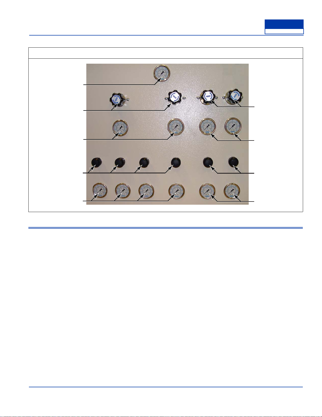
Figure 1-1 Wall Mounted Fill Panel; BFP-100-6
1. Inlet Air Pressure Gauge
2. Pressure Regulators
3. Regulator Gauges
4. Fill Valves
5. Fill Gauges
1
3
5
3
4
22
4
5
4,500 psig 4,000 psig 300 psig 200 psig
BF 100 - 6
Page 5 Special Edition, Rev. 0 Chg. 0
BAUER
COMPRESSORS
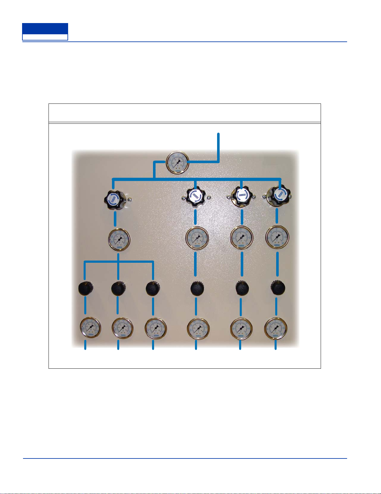
1.6 Pneumatic Flow
The compressed air enters through the inlet, in the back of the unit. It flows to the inlet pressure gauge,
where it is channeled to 4 separate regulators. The regulators are set from left to right (facing the con-
trols) 4,500 psig, 4,000 psig, 300 psig, and 200 psig. The compressed air travels from the regulators
through the regulator gauges down to the bottle fill valves and bottle fill gauges. The air then exits the
bottle fill panel through the back of the panel..
Figure 0.1-1 BFP 100 - 6 Flow
4,500 psig 4,000 psig 300 psig 250 psig
Inlet (in back)
outlets (in back)

MNL-093558
September 30, 2008 Page 6
BAUER
COMPRESSORS
CHAPTER 2: BF SERIES OPERATION
2.1 Bottle Filling Procedures
See Figure 6
^ WARNING ^
Do not attach bottles to outlets units unless the bottle is rated for appro-
priate pressure. (Note pressure stamped on the tank neck)
^ WARNING ^
Never open the fill valve unless the bottle is connected to the fill hose.
Whipping of an unrestrained hose caused by high pressure air discharge
can cause serious injury!
^ CAUTION ^
The filling procedure should not be interrupted for more than 10 minutes
to avoid increased CO2levels in the air filling the bottle.
Figure 2-1 Air Storage Bottle Valve Operating Sequence
1.
2. 1.
2.
Closing Sequence
Attaching the Fill Yoke Opening Sequence

BF 100 - 6
Page 7 Special Edition, Rev. 0 Chg. 0
BAUER
COMPRESSORS
2.1.1 Attaching the Fill Yoke to the Air Storage Bottle
1. Ensure both the fill valve and bottle valve are closed.
2. Connect the air bottle to the BFP fill hose utilizing the fill yoke.
2.1.2 Opening Sequence for Filling the Bottle
1. First open fill valve. (1)
2. Open bottle valve. (2)
3. Bottle will begin filling.
4. During the filling process, monitor bottle pressure on fill valve gauge and drain condensate at the
compressor.
2.1.3 Closing Sequence for After Filling the Bottle
1. First close the bottle valve. (1)
2. Close the fill valve. (2)
3. Remove fill yoke and store compressed air bottle.
MNL-093558
September 30, 2008 Page 8
BAUER
COMPRESSORS
2.1.4 Parts Lists
Item Qty Part No. Description Notes
1 7 GAG-0009W Pressure Gauge 7,500 psi/bar
2 2 REG-0003 Regulator 6,000 psi - in — 0 - 5,000 psi - out
3 2 VAL-0076 Fill Valve (needle valve)
4 2 REG-0013 Regulator 6,000 psi - in — 0 - 400 psi - out
5 4 GAG-0007W Pressure Gauge 600 psi/bar
Figure 2-2 BFP- 100 - 6
1
1
1
5
3
24
3
5
BF 100 - 6
Page 9 Special Edition, Rev. 0 Chg. 0
BAUER
COMPRESSORS
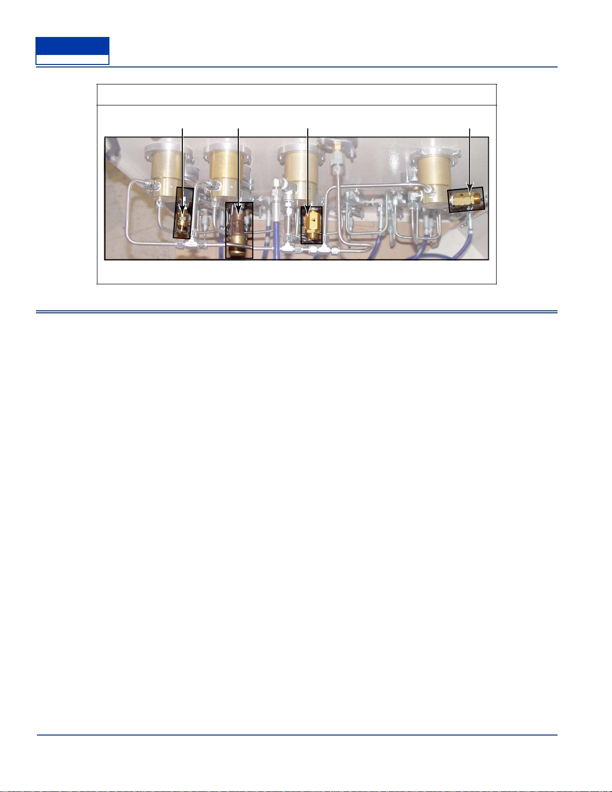
Item Qty Part No. Description Notes
1 1 VAL-0131 Safety Valve set to 275 psig
2 1 VAL-0167 Safety Valve set to 325 psig
3 1 VAL-0169 Safety Valve set to 4,400 psig
4 1 VAL-0169 Safety Valve set to 5,000 psig
Figure 2-3 BFP - 100 - 6 Safety Valves
12 3 3

MNL-093558
September 30, 2008 Page 10
BAUER
COMPRESSORS
CHAPTER 3: MAINTENANCE
3.1 Pressure Gauges
Observe the pressure gauges daily. If the readings of any of the gauges seem to be incorrect, bleed off
all system pressure. Then, remove the gauge and check for wear and tear, accuracy and proper function-
ing by comparing it to a precision test gauge or a dead weight tester. Replace all broken or damaged
gauges immediately.
3.2 Safety Valve
Develop a regular program of visual inspection, looking for clogged drains and discharge pipe, dirt
buildup in and around the valve seat, and broken or missing parts.
Avoid excessive operation of the safety valve, as even one opening can provide a means for leakage.
Safety valves should be operated only often enough to assure that they are in good working order.
Test the valve every two to six months (depending on the surrounding conditions) by raising the system
pressure to the valve's set pressure allowing it to open and reset as it would in normal service. Do not
hand operate the valve with less than 75% of the stamped set pressure exerted on the underside of the
disc. When hand operating, be sure to hold the valve in an open position long enough to purge accumu-
lated foreign material from the seat area and then allow the valve to snap shut.
Do not paint, oil or otherwise cover any interior or working parts of any safety valve. They do not
require any lubrication or protective coating to work properly.
When safety valves require repair, service adjustments or set pressure changes, work shall be accom-
plished by the manufacturer or holders of “V”, “UV” and/or “VR” stamps.
3.3 Tube Connections
Pipe connections (swivel nuts): Tighten just firmly enough so that leakage is stopped (finger tight plus
up to an additional 1/2 turn as necessary). Please note that the compression type coupling fittings are
capable of exerting extreme force on the tubing and should not be tightened more than is required to
seal the joint. To improve the sealing of the pipe connections and to facilitate installation, the following
should be observed:
1. Apply a thin layer of Never-Seez NSWT or equivalent on the outside of the ferrule during assem-
bly.
2. Lubricate the threads of the connector with Never-Seez NSWT or a similar PFTE base lubricant to
facilitate future disassembly.
3.4 Pressure Hoses
The hoses should be inspected periodically for wear and damage. If a hose is worn or damaged, remove
and replace it.

BF 100 - 6
Page 11 Special Edition, Rev. 0 Chg. 0
BAUER
COMPRESSORS
3.5 Storage Bottles
All storage bottles should be visually inspected internally every year.
Every three (3) years, D.O.T. bottles must be hydrotested.
Check local and state regulations regarding testing of ASME and/or D.O.T. bottles.
^ NOTE ^
Some states require an annual visual inspection.
And hydrotesting requirements also differ from state to
state and according to specific bottle types.

MNL-093558
September 30, 2008 Page 12
BAUER
COMPRESSORS
CHAPTER 4: APPENDIX
4.1 Safety
4.1.1 General Safety Precautions
• Read the operating manual before installing or operating this compressor unit. Follow appropriate
handling, operation and maintenance procedures from the very beginning. The maintenance schedule
contains measures required to keep this compressor unit in good condition. Maintenance is simple,
but must be executed regularly to achieve safe operation, maximum efficiency and long service life.
• We recommend that all maintenance work be recorded in a service book, showing the date and details
of the work carried out. This will help to avoid expensive repairs caused by missed maintenance
work. If it is necessary to make a claim against the warranty, it will help to have proof that regular
maintenance has been carried out and that the damage has not been caused by insufficient mainte-
nance.
• This compressor unit must be installed, operated, maintained and repaired only by authorized, trained
and qualified personnel.
• Consult and follow all OSHA, NEMA, ASME and local regulations, laws and codes covering the
installation and operation of this compressor and accessories before operating the unit.
• Do not operate this unit in excess of it’s rated capacity, speed, pressure, temperature, or otherwise
than in accordance with the instructions contained in this manual. Operation of this unit in excess of
the conditions set forth in this manual will subject the unit to limits which it may not be designed to
withstand.
• Keep safety guards in place.
• Do not modify the compressor or its systems.
• Do not wear loose clothing around machinery. Loose clothing, neckties, rings, wrists watches, brace-
lets, hand rags, etc. are potential hazards.
• Provide adequate fire protection. Make sure fire extinguishers are accessible. Select alternate routes
of escape and post such routes.
• Make sure you are equipped with all required safety equipment; hearing protection, safety glasses,
hard hats, safety shoes and fire extinguisher.
• Visually inspect the unit before starting. Remove and /or replace any loose or broken components,
tools, valves, missing equipment, etc.
• Do not tamper with, modify, or bypass safety and shutdown equipment.
• Do not tighten or adjust fitting or connections under pressure.
• The use of plastic pipe or rubber hose in place of steel tube or iron pipe, soldered joints or failure to
insure system compatibility of flex joints and flexible hose can result in mechanical failure, property
damage, and serious injury or death.
• The use of plastic or nonmetallic bowls on line filters without metal guards can be dangerous.
• Replace damaged fan blades promptly. Fan assemblies must remain in proper balance. An unbal-
anced fan can fly apart and create an extremely dangerous condition.

BF 100 - 6
Page 13 Special Edition, Rev. 0 Chg. 0
BAUER
COMPRESSORS
• Allow the compressor to cool before servicing. Whenever the compressor is shut down and over-
heating is suspected, a minimum period of 15 minutes must elapse before opening the crankcase.
Premature opening of the crankcase of an overheated unit can result in an explosion.
• Incorrect placement of the inlet and pressure valves in a compressor cylinder head can cause an
extremely dangerous condition. Refer to the appropriate section of this manual before installing or
replacing valves.
• Before doing any work involving maintenance or adjustment, be sure the electrical supply has been
disconnected, and the complete compressor system has been vented of all internal pressure. Failure to
follow these warnings may result in an accident causing personal injury and/or property damage.
• Before working on the electrical system, be sure to disconnect the electrical supply from the system at
the circuit breaker or other manual disconnect. Do not rely on the ON/OFF switch to disconnect the
electrical supply.
• Installer must provide an earth ground and maintain proper clearance for all electrical components.
• All electrical installation must be in accordance with recognized national, state, and local electrical
codes.
• Do not use gasoline, diesel fuel or other flammable products as a cleaning solution.
• A compressor which has been used for gas service is unsuitable for air applications. Should the
purchaser and/or user proceed to use the compressor for air service after it has been used for gas, the
purchaser/user assumes all liability resulting therefrom without any responsibility being assumed by
Bauer Compressors, Inc. The purchaser is urged to include the above provision in any agreement for
resale of this compressor.
• The use of repair parts other than those listed in this manual or purchased from BAUER Compressors,
Inc. may create unsafe conditions over which BAUER has no control. Such unsafe conditions can
lead to accidents that may be life-threatening, cause substantial bodily injury, and/or result in damage
to the equipment. Therefore, BAUER Compressors, Inc. can bear no responsibility for equipment in
which non-approved repair parts are installed

MNL-093558
September 30, 2008 Page 14
BAUER
COMPRESSORS
4.1.2 Safety Warning Labels
Notes, labels and warning signs are displayed on the compressor unit according to model, application or
equipment and may include any of the following.
HOT SURFACES DO NOT TOUCH!
Danger of burning if cylinders, cylinder heads, or pressure lines of individual
compressor stages are touched.
HIGH VOLTAGE!
Life threatening danger of electrical shock. Maintenance work on electric units
or operating equipment should be carried out by a qualified electrician or by a
person supervised by a qualified electrician according to electrical regulations.
AUTOMATIC COMPRESSOR CONTROL
UNIT MAY START WITHOUT WARNING!
Before carrying out maintenance and repair work, switch off at the main switch
and ensure the unit will not restart.
THE INSTRUCTIONS MUST BE READ BEFORE OPERATING UNIT!
The instruction manual and all other applicable instructions, regulations, etc.
must be read and understood by the operating personnel before using the
machine.
HEARING PROTECTION MUST BE WORN!
Hearing protectors must be worn when working on a machine which is running.
DIRECTION OF ROTATION!
When switching on the machine, check the arrow to ensure correct direction of
rotation by the drive motor.

BF 100 - 6
Page 15 Special Edition, Rev. 0 Chg. 0
BAUER
COMPRESSORS
4.2 Unpacking, Handling and Installation
4.2.1 Unpacking and Handling
This compressor unit is packaged according to the requirements for shipping via the requested type of
carrier service. It is possible that the compressor unit could have been damaged during shipping. For
this reason, we urge you to thoroughly examine the unit for possible damage and report any such dam-
age to the shipping company immediately.
Care must be taken in unpacking the compressor unit. Serious damage could result by not checking for
clearance between the item being unpacked and the packaging to be removed.
Handling of the unpacked unit should be performed using only the following devices.
See Figure 4-1.
The compressor unit may be furnished with one or more shipping braces for shipping and handling
only. After installation and before operation, these braces must be removed entirely. Under no circum-
stances should the braces remain installed during operation or the manufacturer’s warranty for the com-
pressor unit will be voided. The braces are all tagged and labelled.
Figure 4-1 Lifting Devices
^ WARNING ^
Be sure the lifting devices are capable of handling the weight of the unit (see Paragraph 1.4 for the weight
of the unit). Before lifting the unit, secure all loose or swinging parts to keep them from moving.
Stay clear of lifted load.
Fork Lift Hand Truck
Chain Hoist
Table of contents


