Bauer MT1100-HK User manual

Montage- und Bedienungsanleitung
Assembly and operating instructions
Montagetisch MT1100-HK
Mounting Table MT1100-HK
Bauer Systeme:
Vom Praktiker für den Praktiker
Developed by professionals for professionals
DE EN
SondermaschinenbauFördertechnikSteuerungstechnik Handlingsysteme

Montagetisch MT1100-HK | Mounting Table MT1100-HK2
Verwendete Symbole Symbols used
Lesen Sie die sicherheitsbezogenen Informationen und sonsti-
gen Hinweise besonders aufmerksam.
Symbol für eine Handlungsanweisung:
»Der Blickfangpunkt zeigt an, dass Sie eine Handlung durch-
führen sollen.
Sicherheits- und andere Hinweise:
GEFAHR!
Tod, schwere Körperverletzung werden eintreten,
wenn die Gefährdung nicht vermieden wird.
VORSICHT!
Geringfügige oder mäßige Verletzungen können ein-
treten, wenn die Gefährdung nicht vermieden wird.
Mögliche Gefahr für Produkt und Umwelt.
HINWEIS!
Nützliche Informationen und Besonderheiten.
Read the safety-related information and other information
with particular attention.
Symbol identifying required actions:
»The bullet point indicates an action to be performed.
Safety and other notes:
DANGER!
Death, serious physical injury will occur if the hazard
is not avoided.
CAUTION!
Minor or moderate injuries can occur if the hazard is
not avoided. Potential threat to the product and its
environment.
NOTE!
Useful information and special features.
DE EN
Verwendete Symbole Symbols used
DE EN
Inhaltsverzeichnis Contents
Lieferumfang
Hinweise zur Dokumentation
»Bestimmungsgemäße Verwendung
»Spezielle Sicherheitshinweise
»Reparatur und Wartungsmaßnahmen
Sicherheitshinweise
Aufbau Montagetisch
Arbeitsfläche einstellen
Option Montagetisch Verbreiterung
EG - Konformitätserklärung
Seite
3
4
4
4
4
4
5 - 7
8 - 9
10
11
Scope of delivery
Notes on documentation
»Proper use
»General safety instructions
»Special safety instructions
Safety instructions
Assembling the mounting table
Adjusting the work surface
Optional mounting table extension
EC – Declaration of Conformity
Page
3
4
4
4
4
4
5 - 7
8 - 9
10
11

Montagetisch MT1100-HK | Mounting Table MT1100-HK 3
DE Lieferumfang Scope of delivery
EN
Menge
[Stück] Bezeichnung
M8x20
M8x25
M10x16
Quantity
[pieces]
16
6
8
Designation
Linsenschraube
Innensechskant
68x25 Unterlegscheibe
22 M8 Stopp - Mutter
2Rastbolzen mit
Zubehör
2
4
M10x30
M8x16 Rändelschraube
1Federstecker
4Klemmhebel
25 50x50mm Abdeckkappen
4Nutenstein
4Lenkrollen ge-
bremst
2Adapterplatte
2Adapterplatte
17m Filzband
1Spindelwinde
1Kurbel für Spindel
1Schraubadapter für
Spindelwinde
1Fett
15mm Außensechskant-
schlüssel
16mm Außensechskant-
schlüssel
113|10mm Gabelschlüssel
M8x20
M8x25
M10x16
16
6
8
Pan-head screw, hex
socket
68x25 Washer
22 M8 Stop nut
2Locking bolt with
accessories
2
4
M10x30
M8x16 Knurled screw
1Spring pin
4Clamping lever
25 50x50mm Protective caps
4Sliding block
4Lockable castors
2Adaptor plate
2Adaptor plate
17m Felt tape
1Spindle jack
1Crank for spindle
1Screw adaptor for
spindle jack
1Grease
15mm Allen key
16mm Allen key
113|10mm Open-end spanner
10005644
10005646
10005645
10005648
10005647
10005591
10005588
10005589
10005586
10005590
10005617
10005642
10005587
10005608
10005609
10005585
10006026
10006027
10005592
10005752
10005775
10005776
10005777
Artikelnr.: Order No.:
10005644
10005646
10005645
10005648
10005647
10005591
10005588
10005589
10005586
10005590
10005617
10005642
10005587
10005608
10005609
10005585
10006026
10006027
10005592
10005752
10005775
10005776
10005777

Montagetisch MT1100-HK | Mounting Table MT1100-HK4
DE EN
Hinweise zur Dokumentation Notes on documentation
Für zukünftige Verwendung aufbewahren.
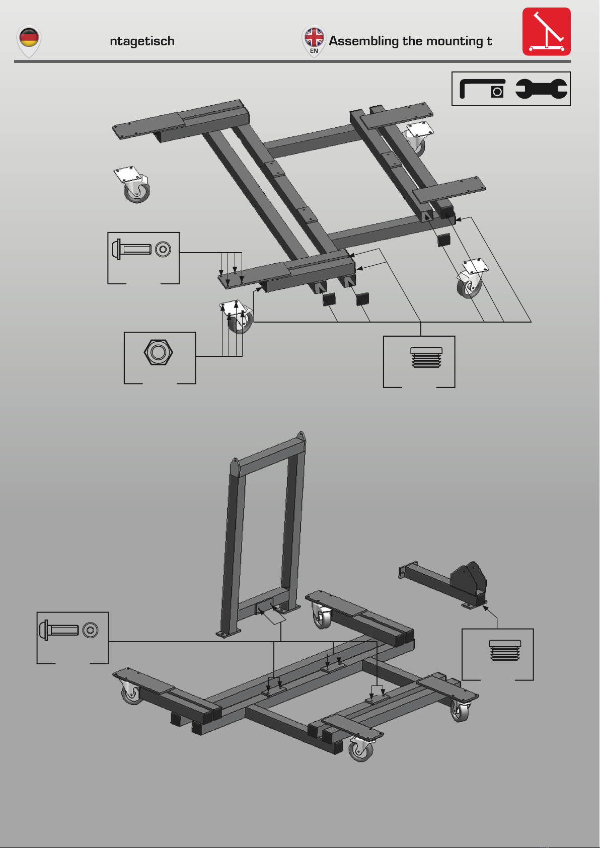
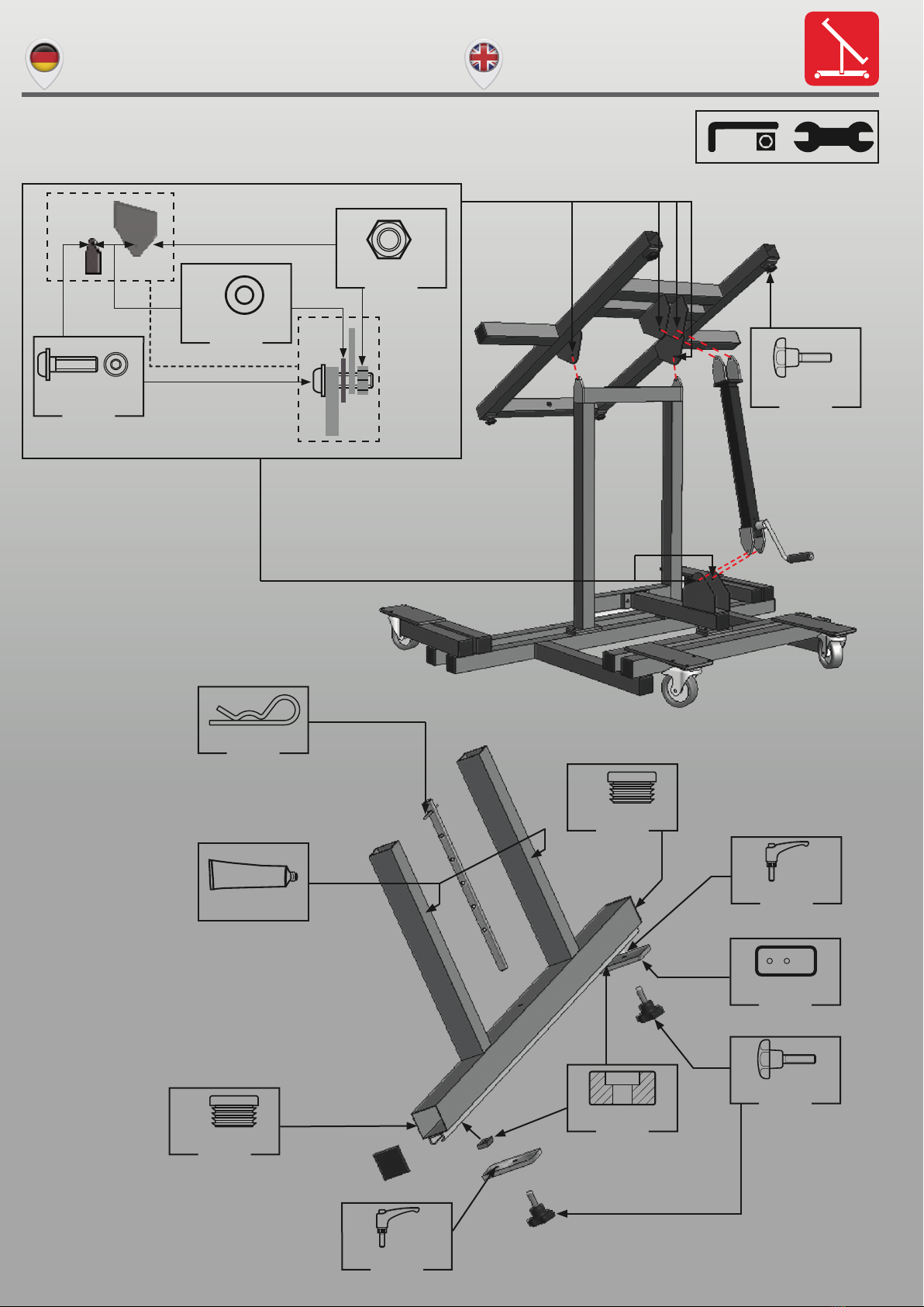
Bestimmungsgemäße Verwendung des MT1100-HK
Der MT1100-HK dient zum Aufbauen und Verdrahten von
Montageplatten bis max. 1100x1900 mm BxH.
Die Beachtung aller Hinweise und die Einhaltung der vor-
geschriebenen Betriebsbedingungen gehören zur bestim-
mungsgemäßen Verwendung.
Spezielle Sicherheitshinweise
»Die vorgeschriebene Höchstlast von 150 kg darf nicht über-
schritten werden.
»Während der Benutzung darf sich keine Person sitzend oder
stehend auf dem Montagetisch aufhalten.
»Vergewissern Sie sich, dass der beladene Montagetisch
gegen unbeabsichtigtes Rollen gesichert ist.
»Stellen Sie sicher, dass die Last gleichmäßig über die
gesamte Arbeitsfläche des Montagetisches verteilt ist.
»Der Montagetisch wurde für ebenen, festen Untergrund kon-
zipiert und ist deshalb für abschüssigen, unebenen Unter-
grund ungeeignet.
»Das Be- und Entladen darf nur in waagerechter Position
erfolgen.
»Der Montagetisch wurde für geschlossene Räume konzipiert
und ist deshalb nicht für Arbeiten im Freien geeignet.
Reparatur- und Wartungsmaßnahmen
Reparatur und Wartung sollten regelmäßig erfolgen, denn sie
wirken sich verlängernd auf die Lebensdauer des Montageti-
sches aus.
Die folgende Überprüfung sollten Sie vor jeder Benutzung
durchführen:
»Die verschiedenen Teile des Montagetisches sollten nicht
verbogen oder gekrümmt sein.
»Testen Sie die Bremsen auf deren Funktion und überprüfen
Sie die Räder auf Verschleiß.
»Schmieren Sie die beweglichen Verschleißteile vor der
Benutzung.
»Im Falle von Defekten sollten die Reparaturen zügig durch-
geführt werden.
»Die Rohrführungen und die Hubspindel sollte einmal im
Monat geschmiert werden.
DE EN
Sicherheitshinweise Safety instructions
Warnung vor der Schließbewegung von mechani-
schen Teilen einer Maschine/Einrichtung
Warnung vor sich bewegenden mechanischen Teilen
Die Anleitung ist zu lesen
Aufsteigen auf eine Fläche ist verboten
!
Store for future use.
Proper use of the mounting table MT1100-HK
The mounting table MT1100-HK is used for assembling and
wiring mounting plates up to a maximum of 1100x1900 mm
WxH.
Compliance with all instructions and observance of the
prescribed operating conditions constitute part of proper
use.
Special safety instructions
»The prescribed maximum load of 150 kg must not be
exceeded.
»Never allow anyone to sit or stand on the mounting table
while in use.
»Ensure that the loaded mounting table is secured against
unintentional rolling.
»Ensure that the load is evenly distributed over the entire
work surface of the mounting table.
»The mounting table is designed for flat, solid subsurfaces,
and is therefore unsuitable for use on sloping, uneven ground.
»The assembly frame must only be loaded and unloaded in a
horizontal position.
»The assembly frame is designed for indoor use, and should
not be used outdoors.
Repairs and maintenance instructions
Repairs and maintenance should be carried out regularly, as
this will prolong the service life of the mounting table.
Carry out the following checks before each use:
»The various parts of the assembly frame should never be
bent or twisted.
»Check the brakes for correct functioning, and examine the
wheels for signs of wear.
»Lubricate movable, wearing parts before use.
»In the event of defects, repairs must be carried out promptly.
»The tubing should be lubricated once a month.
Warning against closing movements for mechanical
parts of a machine/device
Warning against independently moving parts
The instructions must be read
Climbing on surfaces is prohibited
!

Montagetisch MT1100-HK | Mounting Table MT1100-HK 5
DE EN
Aufbau Montagetisch Assembling the mounting table
M8x20
Art.Nr.: 10005644
M8
Art.Nr.: 10005647 50x50
Art.Nr.: 10005617
16x
16x 18x
M10x16
Art.Nr.: 10005645
50x50
Art.Nr.: 10005617
1x
8x

Montagetisch MT1100-HK | Mounting Table MT1100-HK6
DE EN
Aufbau Montagetisch Assembling the mounting table
8x25
Art.Nr.: 10005648
1x
M8
Art.Nr.: 10005647
1x
M8x25
Art.Nr.: 10005646
1x 4x
M8x16
Art.Nr.: 10005589
M10x30
Art.Nr.: 10005588
2x
Art.Nr.: 10005586
1x
Art.Nr.: 10005642
2x
Art.Nr.: 10005590
1x
Art.Nr.: 10005608
1x
50x50
Art.Nr.: 10005617
1x
Art.Nr.: 10005752 Art.Nr.: 10005590
1x
50x50
Art.Nr.: 10005617
1x

Montagetisch MT1100-HK | Mounting Table MT1100-HK 7
DE EN
Aufbau Montagetisch Assembling the mounting table
Art.Nr.: 10005642
2x
Art.Nr.: 10005590
1x
50x50
Art.Nr.: 10005617
1x
Art.Nr.: 10005752
Art.Nr.: 10005590
1x
50x50
Art.Nr.: 10005617
1x
Art.Nr.: 10005609
1x
Art.Nr.: 10005591
2x
Art.Nr.: 10005609
1x
Art.Nr.: 10005585

Montagetisch MT1100-HK | Mounting Table MT1100-HK8
DE EN
Arbeitsfläche einstellen
Adjusting the work surface
DE
Um den Montagetisch auf die Länge der Montageplatte ein-
zustellen, fahren Sie die Arbeitsfläche in die waagerechte
Position. Entfernen Sie den Sicherungssplint am unteren
Auszugsteil. Danach lösen Sie die Arretierungsschrauben und
stellen die gewünschte Länge ein.
Jetzt sind die Arretierungsschrauben wieder festzudrehen
und der Sicherungssplint wieder einzusetzen.
Am oberen Auszugsteil sind die zwei Arretierungsschrauben
zu lösen, um die gewünschte Länge einzustellen.
Danach die Arretierungsschrauben wieder festdrehen, und
die Arbeitsfläche ist auf die Länge der Montageplatte einge-
stellt.
Nun die Montageplatte auf die Arbeitsfläche legen.
Einstellung Länge - Montageplatte
To adjust the assembly frame to the length of the mounting
plate, move the work surface into the horizontal position. Re-
move the safety split pin on the lower extension piece. Then,
loosen the locking screws and adjust to the required length.
Next, re-tighten the locking screws and reinsert the safety
split pin.
Now loosen the two locking screws on the upper extension
piece and adjust to the required length. Then re-tighten the
locking screws, and the work surface is now adjusted to the
length of the mounting plate.
Now place the mounting plate on the work surface.
Adjusting the length – mounting plate
EN
DE
Um das untere Auszugsteil auf die Montageplattenbreite ein-
zustellen, muss sich die Arbeitsfläche in waagerechter Posi-
tion befinden. Lösen Sie die Klemmhebel und stellen Sie die
Adapterplatten auf die gewünschte Breite ein. Die Adapter-
platten müssen so positioniert werden, dass die eingedrehte
Rändelschraube an der Innenseite des U-Profils der Montage-
platte anliegt. Nach der Einstellung der Breite drehen Sie die
Klemmhebel wieder fest. Nun die Rändelschrauben eindrehen.
Einstellung Breite – Montageplatte am unteren
Auszugsteil
To adjust the lower extension piece to the width of the moun-
ting plate, move the work surface into the horizontal position.
Loosen the clamping lever and adjust the adaptor plates to
the required width. The adaptor plates must be positioned in
such a way that the inserted knurled screw is in contact with
the inside of the mounting plate U-profile. After adjusting the
width, re-tighten the clamping lever. Then screw the knurled
screws into position.
Adjusting the width – Mounting plate on the lower
extension piece
EN

Montagetisch MT1100-HK | Mounting Table MT1100-HK 9
Arbeitsfläche einstellen
Adjusting the work surface
DE
Um das obere Auszugsteil auf die Montageplattenbreite einzu-
stellen, muss sich die Arbeitsfläche in waagerechter Position
befinden. Lösen Sie die Klemmhebel und stellen Sie die Ad-
apterplatten auf die gewünschte Breite ein. Die Adapterplat-
ten müssen so positioniert werden, dass die eingefahrenen
Rastbolzen an der Innenseite des U-Profils der Montageplat-
te anliegen. Nach der Einstellung der Breite drehen Sie die
Klemmhebel wieder fest. Jetzt kann mit Hilfe der mitgeliefer-
ten Kurbel die Arbeitsfläche in die gewünschte Stellung gekur-
belt werden.
Entnahme der Montageplatte
Um die fertige Montageplatte wieder zu entnehmen, muss die
Arbeitsfläche in die waagerechte Position gebracht werden.
Nun am unteren Auszugsteil die Rändelschrauben lösen und
am oberen die Rastbolzen zurückziehen und drehen, bis sie
eingezogen bleiben.
Jetzt kann die Montageplatte entnommen werden.
Einstellung Breite – Montageplatten am oberen
Auszugsteil
To adjust the upper extension piece to the width of the moun-
ting plate, move the work surface into the horizontal position.
Loosen the clamping lever and adjust the adaptor plates to
the required width. The adaptor plates must be positioned in
such a way that the inserted locking bolts are in contact with
the inside of the mounting plate U-profile. After adjusting the
width, re-tighten the clamping lever. The work surface can now
be placed in the required position using the crank supplied.
Removing the mounting plate
In order to remove the finished mounting plate, the work sur-
face must be brought to the horizontal position. Next, release
the knurled screws on the lower extension piece, and draw
back and rotate the locking bolts on the upper extension piece
until they remain retracted.
The mounting plate may now be removed.
Adjusting the width – Mounting plate on the upper
extension piece
EN
DE EN

Montagetisch MT1100-HK | Mounting Table MT1100-HK10
DE EN
Option Montagetisch - Verbreiterung
(Art.-Nr.: 10006183)
Optional mounting table exten-
sion (Ord.-No.: 10006183)
Mit dieser Option haben Sie die Möglichkeit, Montageplatten
ab einer Höhe von 1690 mm bis 1896 mm nicht nur vertikal,
sondern auch horizontal auf den Montagetisch zu legen, ohne
auf die bewährten Rastriegel als Montageplattenfixierung ver-
zichten zu müssen.
Damit lassen sich auch sehr große Montageplatten bequem
im Sitzen verdrahten.
Die Tischverbreiterung besteht aus einer linken und einer rech-
ten Verbreiterung in T-Form, die jeweils in den mittleren Holm
des Montagetisches MT1100-HK eingeschoben werden. Dort
werden sie mit den im Set enthaltenen Rändelschrauben
am Montagetisch befestigt.
»Nehmen Sie ein T-Stück und schieben Sie es auf der linken
Seite in den mittleren Holm.
Danach nehmen Sie das andere T-Stück und schieben es auf
der rechten Seite in den mittleren Holm.
»Sind beide T-Stücke in den mittleren Holm geschoben, kön-
nen die T-Stücke mit den mitgelieferten Rändelschrauben
fixiert werden.
Nun können die Rastriegel von oben und unten auf links und
rechts montiert werden.
Jetzt ist der Montagetisch MT1100-HK für die horizontale
Montageplattenfixierung bereit.
This option allows you to position mounting plates from a
height of 1690 mm to 1896 mm on the assembly frame both
vertically and horizontally, without having to forego the tried-
and- trusted lock bolts to secure the mounting plate.
In this way, even very large mounting plates may be wired
whilst seated.
The table extension consists of a left-hand and a right-hand
extension piece in a T-shape, each of which are inserted into
the central upright of the mounting table MT1100-HK. They
are secured to the assembly frame with the knurled screws
included with the set.
»Take a T-section and push it into the central
upright on the left. Then take the other T-section and push it
into the central upright on the right.
»Once both T-sections have been inserted into the central up-
right, they may be secured using the knurled screws sup-
plied.
The lock bolts may now be secured on the left and right from
above and below.
The mounting table MT1100-HK is now ready for horizontal
fixing of the mounting plate.
2
1
1 2
|: 1 2
|:
Rändelschraube zur Fixierung der T - Stücke Knurled screw for securing the T - sections

Montagetisch MT1100-HK | Mounting Table MT1100-HK 11
EG - Konformitätserklärung
Der Hersteller: Bauer Systeme GmbH
Steinäcker 5 - 7
D - 75015 Bretten
erklärt hiermit, dass folgendes Produkt,
Produkttyp: Montagetisch
Bezeichnung des Produktes: MT1100-HK
Einschlägige EU - Richtlinien:
Maschinenrichtlinie 2006/42/EG, Anhang II A
den Bestimmungen der oben gekennzeichneten Richtlinie –
einschließlich der zum Zeitpunkt der Erklärung geltenden
Änderungen – entspricht.
Um die Übereinstimmung zu gewährleisten, wurden ins-
besondere folgende harmonisierte Normen angewendet:
EN ISO 12100-1: 2003 Sicherheit von Maschinen
EN ISO 12100-2:2003 Sicherheit von Maschinen,
technische Leitsätze
EC - Declaration of Conformity
The Manufacturer: Bauer Systeme GmbH
Steinäcker 5 - 7
D - 75015 Bretten
declares herewith that the following product,
Product Type: Mounting table
Product Description: MT1100-HK
Relevant EU – Guidelines:
EC – Machine Guideline 2006/42/EC, Appendix II A
conforms to the regulations of the above quoted guideline –
including the amendment, which is valid at the time of the
declaration.
In particular the following harmonised norms were
applied to guarantee conformity:
EN ISO 12100-1: 2003 Safety of machinery
EN ISO 12100-2: 2003 Safety of machinery,
technical principle
DE EN
EG - Konformitätserklärung EC - Declaration of Conformity
Hartmuth Bauer
(Geschäftsführer)
René Alldinger
(Geschäftsführer)
Hartmuth Bauer
(Manager)
René Alldinger
(Manager)

Bauer Systeme:
Vom Praktiker für den Praktiker
Developed by professionals for professionals
Elektrokonstruktion
Schaltanlagenbau
Softwareplanung
Service und Wartung
Fördertechnik
Sondermaschinenbau
Handlingsysteme für
Schaltanlagenbau
Steinäcker 5-7 · D-75015 Bretten
Tel.: +49 (7252) 58 377-0 · Fax: +49 (7252) 58 377-50
SondermaschinenbauFördertechnikSteuerungstechnik Handlingsysteme
© Copyright by Bauer Systeme GmbH - Rev. 1.0 -19-10-20
www.bauersysteme.de/kontakt
www.bauersysteme.de/produkte
www.bauersysteme.de/produkte/lager-transportwagen
www.bauersysteme.de/produkte/laengenanschlag
www.bauersysteme.de/produkte/montageplatten-aufbau-systemwww.bauersysteme.de/produkte/smarttable
www.bauersysteme.de/produkte/montagetisch-mt1100-hk
www.bauersysteme.de/produkte/eworkstation
www.bauersysteme.de/produkte/smartlifter
Table of contents
Other Bauer Indoor Furnishing manuals
Popular Indoor Furnishing manuals by other brands

overstock
overstock WF288548 Assembly instructions

WELLFOR
WELLFOR ERIC-M1FM7236 Installation

Bob's Discount Furniture
Bob's Discount Furniture Mystic Bay Dresser & Mirror Assembly instructions

U-Line
U-Line H-8277 manual

Universal Furniture
Universal Furniture Explore Home 932-632 instruction sheet

Powell
Powell 233-314AT2 Assembly instructions

DIVERSIFIED WOODCRAFTS
DIVERSIFIED WOODCRAFTS 4111 Series Assembly instructions

Dorel Home Products
Dorel Home Products Queer Eye 4538439QE Instruction booklet

Bush
Bush AC99820-03 manual

Sauder
Sauder Shoal Creek Armoire manual

Furniture of America
Furniture of America YNJ-1462 Assembly instructions

MOBISUL
MOBISUL MALAGA 400051 instruction manual