BAUMAN 640H User manual

BAUMAN
MANUFACTURING
640H/640P DROP SPREADERS
OPERATOR’S MANUAL


1
Contents
INTRODUCTION.......................................................................................................................................................................2
GENERAL INFORMATION ........................................................................................................................................................3
SAFETY INSTRUCTIONS............................................................................................................................................................ 4
SAFETY LABELS ....................................................................................................................................................................5
MAINTENANCE........................................................................................................................................................................ 6
ATTACHMENT OF THE MACHINE ............................................................................................................................................6
SPREADING MATERIAL............................................................................................................................................................7
HYDRAULIC ROUTING INSTRUCTIONS ....................................................................................................................................7
640H/640P PARTS LIST............................................................................................................................................................8
640H, HYDRAULIC SPECIFIC PARTS LIST.................................................................................................................................. 9
640P, PTO SPECIFIC PARTS LIST ..............................................................................................................................................9
INSTALLATION LOCATIONS ...................................................................................................................................................10
OPTIONAL ATTACHMENTS....................................................................................................................................................16
WARRANTY INFORMATION...................................................................................................................................................17

2
INTRODUCTION
Congratulations on your purchase of a Bauman Drop Spreader! This spreader has been
designed and manufactured to enable operators to carry out their work safely and efficiently.
The Bauman Drop Spreader is capable of spreading sand, salt, grit, or similar materials and
should only be used for this purpose. Correct usage of the machine also includes following the
factory’s preparation, operation and maintenance instructions.
This manual will help you understand the proper maintenance and operation of the spreader
in order to maximize the longevity and effectiveness of the machine. All information,
illustrations and technical specifications in this manual are based on the most recent product
information available at the time of printing.
Bauman Manufacturing reserves the right to change the design and specifications and/or
make additions and improvements to the product without notice.

3
GENERAL INFORMATION
The operator must read and understand the information in this
manual to ensure the correct service and operation of the machine
and avoid unnecessary risk of accidents and breakdowns.
Please Note:
Stop the tractor engine before you adjust, lubricate, or repair the machine. Remember to
remove the ignition key to make sure no one starts the tractor while you are repairing the
machine.
Do not let anyone underneath the machine once it is connected to the tractor. Always
disconnect power when servicing.
Do not let anyone get close to or stay close to the machine while it is in operation. Do not
squeeze between the machine and the tractor as an unintentional maneuver may result in
serious injury.
Make certain that the hydraulic components are not subjected to continuous operating
pressure exceeding 1800 psi or intermittent pressures of 2350 psi. A higher pressure may
cause danger of exploding parts, hot oil exposure, or component failure.
Tractor Requirements:
It is recommended that the tractor operator use hearing protection in case of insufficient
sound insulation in the cab. In order to keep full control of the tractor in all circumstances, at
least 20% of the tractor’s total weight should be on the front axle. It may be necessary to
regulate weight distribution with additional weights.
Do not overload your vehicle beyond the manufacturer’s payload limits. If there are any
questions concerning weight limits, contact vehicle manufacturer.
Material Density Guideline*
Fine Salt (Dry)
85 lbs./cubic foot
Coarse Salt (Dry)
55 lbs./cubic foot
50/50 Sand/Salt Mix
100 lbs./cubic foot
*Material densities are provided for estimation only. Actual material densities may vary.

4
SAFETY INSTRUCTIONS
This machine demands skilled operation therefore, you must read this operator’s manual
before connecting the machine to the tractor. Even though you may have owned or operated
similar equipment, you should read through the safety and maintenance procedures
thoroughly. This concerns your safety.
The Bauman Drop Spreader should only be operated by one person. The operator should
ensure that no one is close to the area where the machine is in use. Do not let others operate
the machine unless you are certain that they have the necessary knowledge to operate the
machine safely and correctly.
The following precautions should be read and understood before operation of the machine:
▪Activate the tractor’s parking brake and stop the tractor’s engine before:
•Unclogging material jams;
•Lubricating the machine;
•Cleaning the machine;
•Disassembling any part of the machine;
•Adjusting, repairing, or maintaining the machine.
▪Lower the machine to the ground when parked.
▪Disconnect power before servicing.
▪Do not work underneath an elevated unit until it has been secured mechanically or with
stop wedges.
▪Do not start or operate the tractor until bystanders are clear of the machine.
▪Check to make sure that all tools have been removed from the machine before starting
the tractor.
▪Check that all safety shields and grills are in place and secured.
▪Do not operate the machine while wearing loose garments.
▪Use statutory vehicle lights and safety markings when operating the spreader on public
roads or when driving in the dark.
▪Hearing protection is recommended, especially if the machine is in use over a long
period of time.
▪Before lifting or lowering the spreader, ensure there is no one in the vicinity of the
machine. Do not stand between the tractor and the spreader during attachment and
detachment.
▪The machine has been manufactured strictly for the intended use as a drop spreader.
Do not use the machine for any other purpose.
▪Be considerate of people, property and animals near the machine. Maintain a distance
of at least 10 meters from obstacles while operating from the machine.

5
▪Use only original components or replacement components received from Bauman
Manufacturing.
▪Sitting, reaching into or climbing on or in the spreader during operation can result in
serious injury or death. Do not ride on the spreader while the vehicle is in motion.
▪All laws and rules relating to public safety in the country of operation must be obeyed.
Follow both the vehicle and spreader manuals to ensure safety and mechanical
efficiency.
It is the operator’s responsibility to ensure the safety of themselves and others
while operating or maintaining a Bauman Drop Spreader.
SAFETY LABELS
The danger labels on Bauman Manufacturing equipment are for the safety of the operator as
well as pedestrians and bystanders. Read and obey warning and danger labels. The operator
must ensure that before operating the machine, all guards and grills are in place and that they
are attached properly. Stay clear of all moving parts and rotating shafts.
Under no circumstances should anyone reach into the
hopper when the spreader is in operation.

6
MAINTENANCE
Warning: When repairing, maintaining and cleaning the machine, it is particularly important
to be aware of the safety precautions. Park the tractor (if connected) as a precautionary
measure and disconnect power when servicing. Do not clean, lubricate or adjust the machine
before the tractor engine has been stopped and the parking brake is activated.
Important: Screws and bolts on your new machine must be tightened up after the first two
hours of operation. All moveable parts must be greased regularly for the best performance.
To extend the durability of the machine, frequent and thorough cleaning is recommended. Set
spring tension to loosest setting for ease of cleaning the machine and use plenty of water
when cleaning to avoid material freezing on the roller or rubber belts.
Remember: Do not spray water directly into bearings or bearing housings. If the machine is
stored for a lengthy period of time, spray it with acid-free oil before use. Remove all foreign
material from the roller. Check and lubricate all chain and bearings regularly.
It is important to properly maintain and service your spreader. Failure to comply
with the manufacturer’s suggested servicing procedures may result in premature
wear and may hinder the machine’s performance.
ATTACHMENT OF THE MACHINE
This spreader can be attached to the tractor using various methods. It is the operator’s
responsibility to make sure that it is connected and fastened properly and safely. Ensure that
the spreader sits horizontally when in operation.
Hydraulic Units: Ensure the hydraulic hoses are properly connected to the tractor’s hydraulic
ports. Improper connection may damage the machine if the oil runs in the wrong direction.
Flow control and hoses to the motor are included.
PTO Units: Attach PTO shaft to the tractor. Make sure that the PTO yoke push pin is engaged
properly. Ensure the PTO shaft is cut to the proper length so there is no tension on the
gearbox when the spreader is raised. PTO shaft is included.

7
SPREADING MATERIAL
REGULATING SPREAD QUANTITY
The spreading quantity is adjusted with the tension adjustment lever. Correct adjustment is
important. If the adjustment is too tight, unnecessary wear of the rubber belts or rotating parts may
occur. If the adjustment is too slack, distribution of material will be uneven.
Hydraulic Units: All hydraulic units are equipped with hydraulic flow control. To ensure to correct
rate of drop of material, the operator would adjust the tension adjustment lever, hydraulic flow
control, engine RPM, and ground speed. Adjusting engine RPM impacts hydraulic flow.
PTO Units: To ensure the correct rate of drop of material, the operator would adjust the tension
adjustment lever, engine RPM, and ground speed.
STARTING TO SPREAD
Spreading of material starts as soon as the tractor’s PTO, hydraulic, or electrical system is engaged.
HYDRAULIC ROUTING INSTRUCTIONS
Hydraulic: The hydraulic spreader models come equipped with the hoses and fittings already
installed in their intended orientation. Ensure the tractor hoses are attached in such a way that
allows for the agitator and distributor drum to rotate in the direction shown in Figure A. A decal
depicting the correct rotation direction has also been positioned near the bearings supporting these
shafts.
Figure A:
Direction of Drum
Rotation

8
640H/640P PARTS LIST
ITEM
#
PART NUMBER
DESCRIPTION
HYD
QTY.
PTO
QTY.
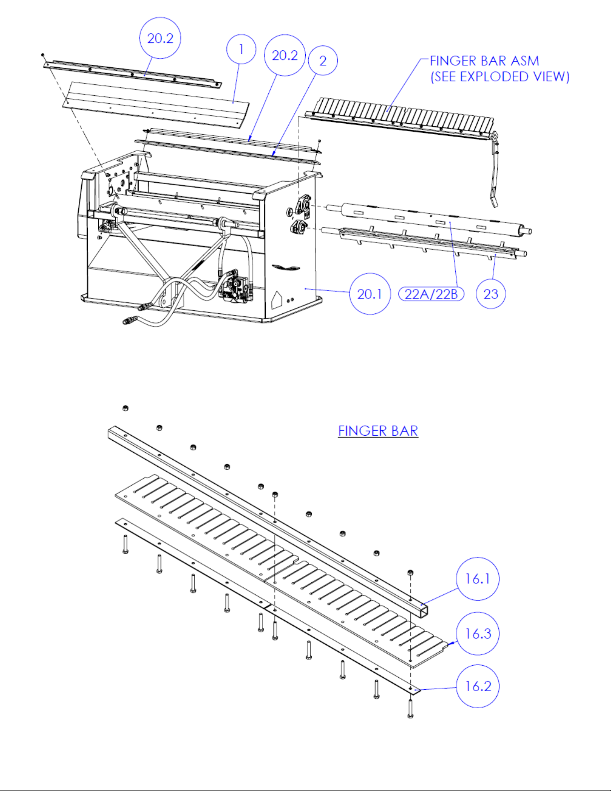
1
1140 SB50-4
RUBBER FLAP FINGER BAR 40
1
1
2
1140 SB60-4
RUBBER FLAP DISTRIBUTOR DRUM 40
1
1
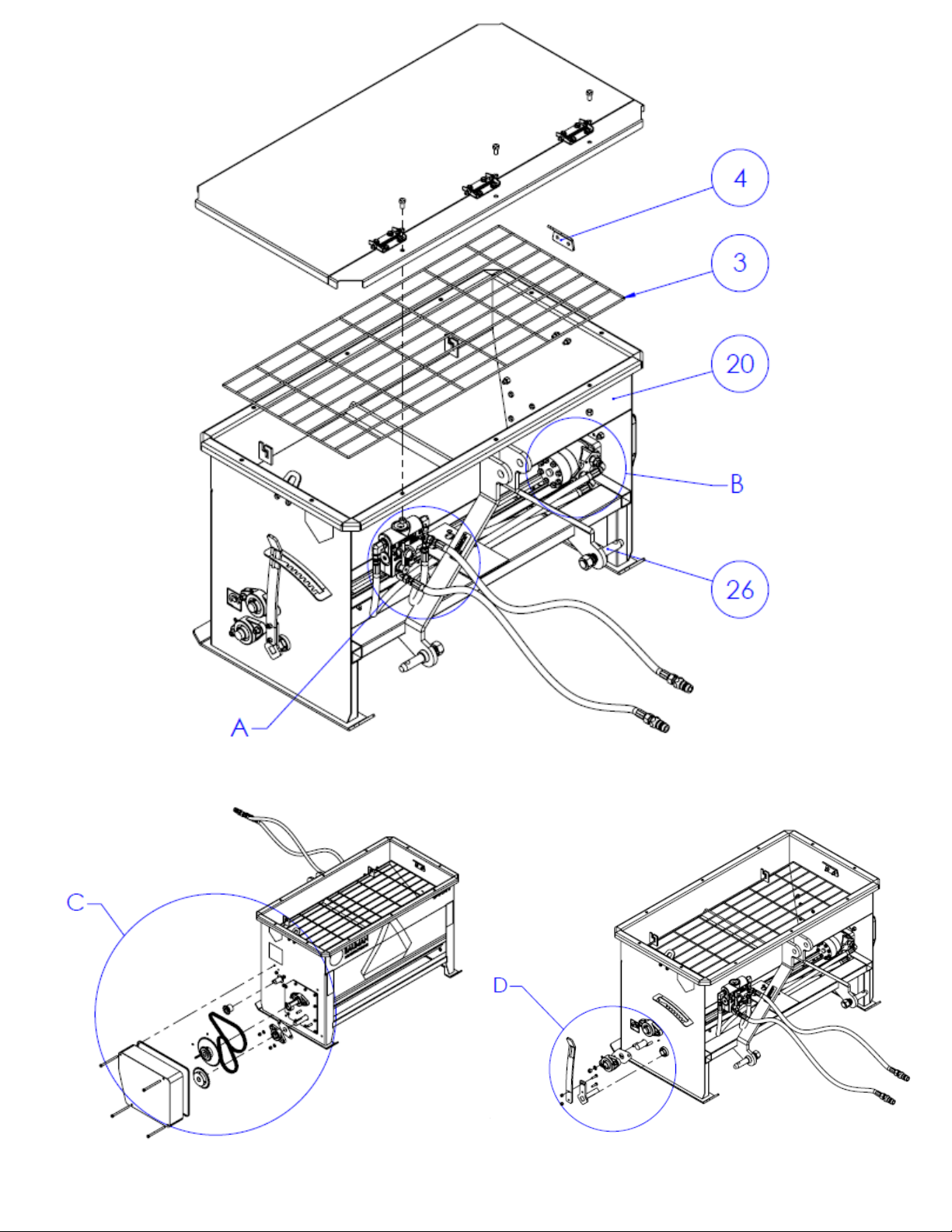
3
640 200
GRILL - HOPPER
1
1
4
1140 800
HOOK BRACKET
2
2
5
40B30 100
#40-30 TOOTH 1" BORE
1
1
6
AP SMV 102
SMV DECAL
1
1
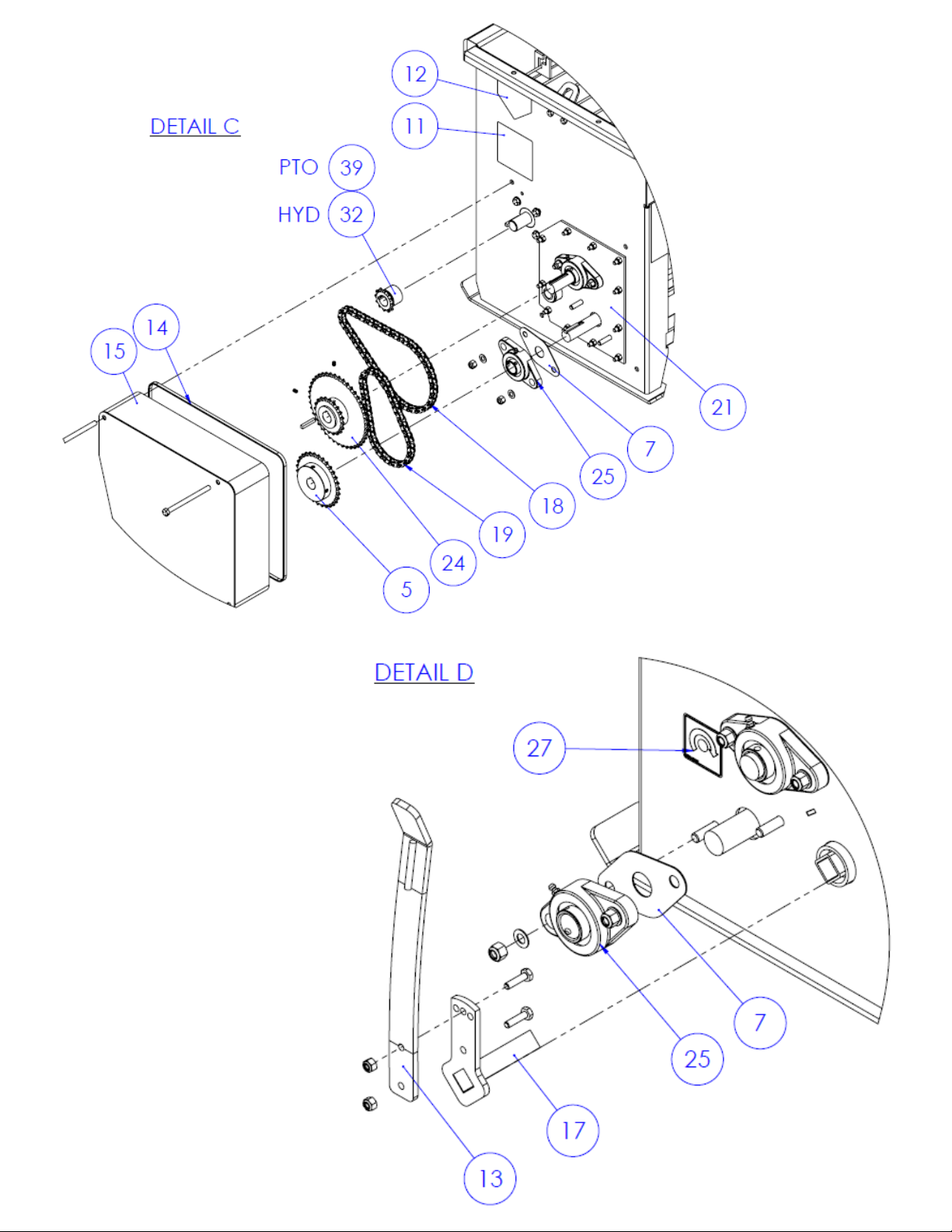
7
BSFL 205-16
BEARING BACKSTOP-NEOPRENE
4
4
8
DECAL SERIAL #
SERIAL # DECAL
1
1
9
DECAL WHITE TAPE
2" WIDE, WHITE REFLECTOR TAPE
2
2
10
DECAL BAUMAN LOGO 12"
BAUMAN DECAL HORIZONTAL
1
1
11
DECALSW404
MOVING PART HAZARD
1
1
12
DECALW803
KEEP HANDS/FEET AWAY
2
2
13
1140 305
TENSION LEVER FOR 1140/640
1
1
14
1140 201 SEAL
RUBBER SEAL
1
1
15
1140 201
SHIELD
1
1
16
1140 301
FINGER BAR ASSEMBLY
1
1
16.1
1140 301-001
FINGER BAR TUBE 40
1
1
16.2
220 301 GALV STRIP
FINGER BAR STRIP
2
2
16.3
220 R-24527
FINGER BAR "RED" 5"x19 3/4"x3/16"
2
2
17
1140 310
TENSION LEVER BASE 40"
1
1
18
1140 410
#40 ROLLER CHAIN WITH C/LINK - DRIVE
1
1
19
1140 411
#40 ROLLER CHAIN WITH C/LINK - DRUM
1
1
20
640 BASE
HOPPER WELDMENT
1
1
20.1
640 BASE HOPPER
MAIN SPREADER WELDMENT
1
1
20.2
CLAMP CHANNEL 40
RUBBER FLAP CLAMPING PLATE
2
2
21
1140 430
BEARING PLATE
1
1
22A
1140 302
DISTRIBUTOR DRUM (SAND), SHAFT WITH STUDS
1
(A or B)
1
(A or B)
22B
1140 302 SALT 01
DISTRIBUTOR DRUM (SALT), SHAFT WITH GROOVES
23
1140 303
AGITATOR
1
1
24
1140 400
DOUBLE SPROCKET
1
1
25
UCFL 205-16
TWO BOLT FLANGE BEARING
4
5
26
ELLP2216U
LIFT ARM PIN (7/8"X1-3/4"X5-1/2" OAL)
2
2
27
DECAL CW ROT
CLOCK-WISE ROTATION INDICATOR
1
1
28
640 LID
METAL LID ASM (OPTIONAL ATTACHMENT)
--
--

9
640H, HYDRAULIC SPECIFIC PARTS LIST
ITEM
#
PART NUMBER
DESCRIPTION
HYD
QTY.
PTO
QTY.
29
1140 900
HYD HOSE CLAMP
1
0
30
HYD FLOW
FLOW CONTROL VALVE 8GPM
1
0
31
SEE BOM
HYD KIT FLOW, HOSES AND FITTINGS
1
0
31.1
HYD6602-6-6-6
SWIVEL NUT RUN TEE - MJIC x MJIC x FJIC
1
0
31.2
HYD6801-6-8
STRAIGHT THREAD ELBOW - MJIC x MORB 90°
3
0
31.3
HYD6400-6-10
STRAIGHT THREAD CONNECTOR - MJIC x MORB
2
0
31.4
HYD HOSE 36 TRACTOR
3/8 3000 PSI 3/8 JIC STRAIGHT x PIONEER END
2
0
31.5
HYD HOSE 46
3/8 3000 PSI 3/8 JIC STRAIGHT X 3/8 JIC 90 ELBOW
1
0
31.6
HYD HOSE 38
3/8 3000 PSI 3/8 JIC STRAIGHT X 3/8 JIC 90 ELBOW
1
0
32
40B12 100 EXT
#40-12 TOOTH 1" BORE EXT. HUB
1
0
33
DECAL 640H
MODEL # FOR HYD 175L (HYD)
1
0
34
HYD-MLHPQ-100-100
HYDRAULIC MOTOR - 5/8" ORB PORTS
1
0
640P, PTO SPECIFIC PARTS LIST
ITEM
#
PART NUMBER
DESCRIPTION
HYD
QTY.
PTO
QTY.
35
B1D051USA60002
PTO SHAFT #1 27" OAL
0
1
36
L25A 124.489
GEAR BOX 2.75:1
0
1
37
1140 421
PTO COUPLER SHAFT
0
1
38
193-0116
U-JOINT ASSEMBLY
0
1
39
40B12 100
#40-12 TOOTH 1" BORE
0
1
40
DECAL 640P
MODEL # FOR HYD 175L (PTO)
0
1
41
DECALSW101
ROTATING DRIVELINE
0
1
42
1140 202
GEAR BOX SHIELD
0
1
43
1140 203
SHAFT COVER (PTO)
0
1

10
INSTALLATION LOCATIONS
CONNECTION SIDE, HYDRAULICS
CONNECTION SIDE, PTO
11
12

13
14

15

16
OPTIONAL ATTACHMENTS
GALVANIZED METAL LID
Part Number: 640 LID
6” Extension adds 2-1/2 cu.ft.
Part Number: 640 EXT
12” Extension adds 5 cu.ft.
Part Number: 640 EXT-12
CUSTOM MOUNTING BRACKETS
Contact Bauman Manufacturing to find a
suitable mounting bracket.
(Multihog mounting bracket shown)
3 POINT HITCH QUICK ATTACHMENT
Part Number: BRACKET 3PT SSL

17
3 INDUSTRIAL DRIVE
ELMIRA, ON N3B 2S1
PHONE: (519)669-4333
FAX: (519)669-2431
WWW.BAUMANMFG.COM
WARRANTY INFORMATION
One Year Limited Warranty
If the unit fails to operate within one year from date of purchase because of defects in
materials or workmanship, Bauman Manufacturing will, at its option, either replace or repair
such components for the original purchaser. This warranty does not cover damage resulting
from accident, misuse or abuse, water, tampering, servicing performed or attempted by
unauthorized agencies, or units that have been modified in any fashion. If the components do
not perform as warranted herein, the original purchaser’s sole remedy will be the repair or
replacement of the components as provided above. Bauman Manufacturing products are not
intended for applications where a failure could result in a costly, dangerous or life-threatening
situation. Bauman Manufacturing will not be held responsible for damages or losses greater
than the cost of the Bauman Manufacturing replacement parts. In no event will Bauman
Manufacturing be liable for damages, lost revenue, lost wages, lost savings or any other
incidental or consequential damages, domestic or international, rising from the purchase and
use or inability to use the components, even if Bauman Manufacturing has been advised of the
possibility of such damages. Except as provided herein, Bauman Manufacturing makes no
warranties, expressed or implied, including without limitation, the implied warranties of
merchantability and fitness for a particular purpose, with respect to the components. All
warranties for the components expressed or implied, are limited to the warranty period set
forth above.
WARRANTY SERVICE
In order to obtain the remedy of repair or replacement parts, contact Bauman Manufacturing.

18
This manual suits for next models
1
Table of contents
Other BAUMAN Spreader manuals


Popular Spreader manuals by other brands

Douglas Dynamics
Douglas Dynamics SnowEx V-Pro SP-2000 installation instructions

STAR INDUSTRIES
STAR INDUSTRIES 1160B Operator's manual

Meyer's
Meyer's 390 Tandem INSTRUCTION AND PARTS BOOK

Texas Equipment
Texas Equipment Smart Spreder 200 user manual

PermaGreen Supreme
PermaGreen Supreme MAGNUM SmartSteer C3C 2009 Operator's manual

SnowEx
SnowEx Sidewalk-Pro SD-95 instruction manual


