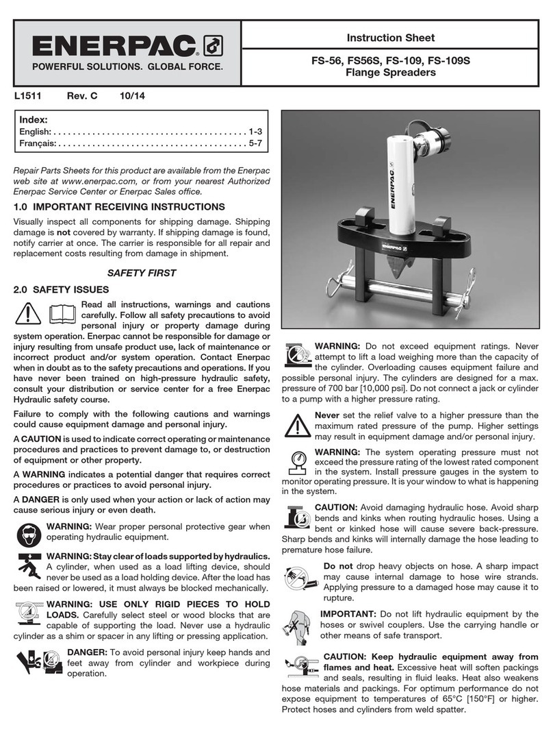
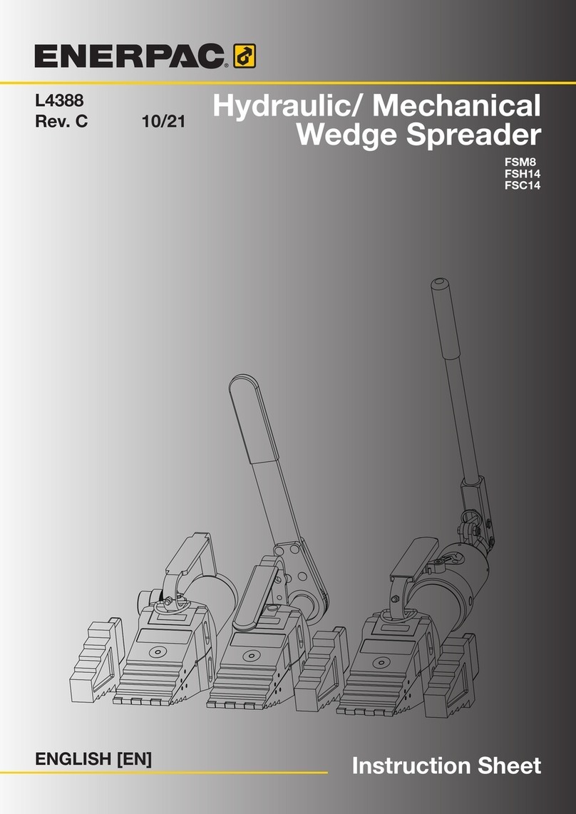
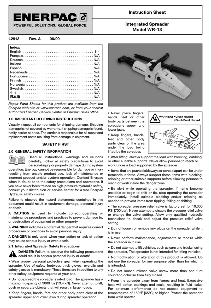
Enerpac FS-56 User manual

Repair Parts Sheets for this product are available from the Enerpac
web site at www.enerpac.com, or from your nearest Authorized
Enerpac Service Center or Enerpac Sales office.
1.0 IMPORTANT RECEIVING INSTRUCTIONS
Visually inspect all components for shipping damage. Shipping
damage is not covered by warranty. If shipping damage is found,
notify carrier at once. The carrier is responsible for all repair and
replacement costs resulting from damage in shipment.
SAFETY FIRST
2.0 SAfETy ISSUES
Read all instructions, warnings and cautions
carefully. Follow all safety precautions to avoid
personal injury or property damage during system
operation. Enerpac cannot be responsible for damage or injury
resulting from unsafe product use, lack of maintenance or incorrect
product and/or system operation. Contact Enerpac when in doubt as
to the safety precautions and operations. If you have never been
trained on high-pressure hydraulic safety, consult your distribution
or service center for a free Enerpac Hydraulic safety course.
Failure to comply with the following cautions and warnings could
cause equipment damage and personal injury.
A CAUTION is used to indicate correct operating or maintenance
procedures and practices to prevent damage to, or destruction of
equipment or other property.
A WARNING indicates a potential danger that requires correct
procedures or practices to avoid personal injury.
A DANGER is only used when your action or lack of action may
cause serious injury or even death.
sgls.eps
WARNING: Wear proper personal protective gear when
operating hydraulic equipment.
undr.eps
WARNING: Stay clear of loads supported by hydraulics.
A cylinder, when used as a load lifting device, should
never be used as a load holding device. After the load has
been raised or lowered, it must always be blocked mechanically.
®
®
blkd.eps
WARNING: USE ONLY RIGID PIECES TO HOLD LOADS.
Carefully select steel or wood blocks that are capable of
supporting the load. Never use a hydraulic cylinder as a
shim or spacer in any lifting or pressing application.
DANGER: To avoid personal injury keep hands and
feet away from cylinder and workpiece during
operation.
Dexceed.eps
WARNING: Do not exceed equipment ratings. Never
attempt to lift a load weighing more than the capacity of
the cylinder. Overloading causes equipment failure and
possible personal injury. The cylinders are designed for a max.
pressure of 700 bar [10,000 psi]. Do not connect a jack or cylinder
to a pump with a higher pressure rating.
danger.eps
Never set the relief valve to a higher pressure than the
maximum rated pressure of the pump. Higher settings
may result in equipment damage and/or personal injury.
gge.eps
WARNING: The system operating pressure must not
exceed the pressure rating of the lowest rated component
in the system. Install pressure gauges in the system to
monitor operating pressure. It is your window to what is happening
in the system.
hosbnd.eps
CAUTION: Avoid damaging hydraulic hose. Avoid sharp
bends and kinks when routing hydraulic hoses. Using a
bent or kinked hose will cause severe back-pressure.
Sharp bends and kinks will internally damage the hose leading to
premature hose failure.
®
drag.eps
Do not drop heavy objects on hose. A sharp impact
may cause internal damage to hose wire strands.
Applying pressure to a damaged hose may cause it to rupture.
IMPORTANT: Do not lift hydraulic equipment by the
hoses or swivel couplers. Use the carrying handle or
other means of safe transport.
CAUTION: Keep hydraulic equipment away from
flames and heat. Excessive heat will soften packings
and seals, resulting in fluid leaks. Heat also weakens
hose materials and packings. For optimum performance do not
expose equipment to temperatures of 65°C [150°F] or higher.
Protect hoses and cylinders from weld spatter.
inject.eps
DANGER: Do not handle pressurized hoses. Escaping
oil under pressure can penetrate the skin, causing serious
injury. If oil is injected under the skin, see a doctor immediately.
Instruction Sheet
fS-56, fS56S, fS-109, fS-109S
flange Spreaders
L1511 Rev. B 03/10

2
bdyhit.eps
WARNING: Only use hydraulic cylinders in a coupled
system. Never use a cylinder with unconnected couplers.
Ifthecylinderbecomesextremelyoverloaded,components
can fail catastrophically causing severe personal injury.
®
stblty.eps
WARNING: BE SURE SETUP IS STABLE BEFORE
LIFTING LOAD. Cylinders should be placed on a flat
surface that can support the load. Where applicable, use a
cylinder base for added stability. Do not weld or otherwise modify
the cylinder to attach a base or other support.
danger.eps
Avoid situations where loads are not directly centered on
the cylinder plunger. Off-center loads produce
considerable strain on cylinders and plungers. In addition,
the load may slip or fall, causing potentially dangerous results.
Distribute the load evenly across the entire saddle
surface. Always use a saddle to protect the plunger.
IMPORTANT: Hydraulic equipment must only be serviced
by a qualified hydraulic technician. For repair service,
contact the Authorized ENERPAC Service Center in your
area. To protect your warranty, use only ENERPAC oil.
sman.eps
WARNING: Immediately replace worn or damaged parts
by genuine ENERPAC parts. Standard grade parts will
break causing personal injury and property damage.
ENERPAC parts are designed to fit properly and withstand high
loads.
Flange Spreader Selection Chart
Model Side Lock 1/8 – 1 1/8” 1 3/16 – 2 3/16” Wt.
No. Pump Hose Cylinder Crossbar Plate Pin Pin Adaptor Wedge Wedge Lb.
FS-56 — — RC-53ST F56-2 (2) F56-3 F56-4 (2) F109-8 F56-5 F109-6 F109-7 (optional) 26
FS-56S P-142 HC-9206Q RC-53ST F56-2 (2) F56-3 F56-4 (2) F109-8 F56-5 F109-6 F109-7 (optional) 34
FS-109 — — RC-102 F109-2 (2) F109-3 F109-4 (2) F109-8 F109-5 F109-6 F109-7 (optional) 40
FS-109S P-392 HC-9206 RC-102 F109-2 (2) F109-3 F109-4 (2) F109-8 F109-5 F109-6 F109-7 (optional) 52
Metal box included with FS-56, FS-56S, FS-109, FS-109S.
Adaptor Wedge
Lockpin (2)
Pin
Side Plate (2)
Cylinder
Crossbar
Figure 1

3
ASSEMBLy INSTRUCTIONS
1. Before assembly, identify all component parts included with
the set. Refer to the Flange Spreader Selection Chart for
identification of the component parts and to Figure 1 to aid in
the assembly procedure.
2. Hand tighten the hydraulic cylinder into the crossbar making
sure the cylinder collar threads are fully engaged. (For cylinder
RC-102, first remove thread protector.)
3. Thread the adaptor (F56-5 or F109-5) into the end of the
cylinder plunger until fully engaged, hand tighten only.
4. Thread the wedge provided (or the optional wedge, if desired)
into the adaptor until fully engaged, hand tighten only.
5. Insert the small head of one of the side plates through the
slot in one end of the crossbar and rotate 90°. Repeat this
procedure for the other side plate into the slot at the opposite
end of the crossbar. The spreader is now ready to be slipped
onto the flange.
6. Connect the hose assembly to the proper port on your pump.
Use Teflon tape on the pipe threads and tighten with a
wrench.
IMPORTANT NOTE: Teflon tape is an excellent thread sealer.
However, if the tape is not properly applied, pieces may enter
the hydraulic system causing malfunctions and component
damage. Use 1-1/2 wraps of tape on each connection, leaving
the starting thread free of tape. Cut off all loose tape ends.
danger.eps
WARNING: If an Enerpac pump is not used, be
sure your pump does not exceed the rated capacity
of the flange spreader. Failure to do so could result
in personal injury or property damage.
OPERATING INSTRUCTIONS
IMPORTANT NOTE: Prepare the flange by loosening all the
bolts and removing one bolt for the insertion of the flange
spreader pin. Removal of the remaining bolts may be necessary
depending on your flange maintenance application. In some
cases, leaving one or two loosened bolts in the flange may be
helpful for realignment of the flange halves. Qualified personnel
should determine the proper method of preparation.
1. Slip the assembled spreader onto the flange. Align the holes
in the side plates with the flange bolt holes and insert the pin
through the side plates and bolt holes as shown in Figure B.
Insert the lockpins. Keep the side plates, pin and crossbar
centered on the flange.
2. Rotate the wedge clockwise allowing the tapered sides to
be forced between the flange faces. If the wedge cannot
be rotated sufficiently in a clockwise direction for proper
alignment, then rotate it counter-clockwise just enough to
align it with the flange. See Figure 2.
danger.eps
WARNING: Keep side plates close to flange face
while applying pressure Exceeding 1/4 inch
distance between side plate and flange face could
result in personal injury or property damage.
3. Connect the quick coupler on the hose to the quick coupler on
the cylinder and hand tighten.
Figure 2
4. Apply light pressure with the hand pump and check that
all connections fit securely. If so, proceed with the flange
spreading operation. If not, make needed adjustments before
proceeding.
NOTE: A light coating of grease on the wedge tapers will make
it easier for the wedge to be forced between the flange faces.
CAUTION: Do not force the wedge between the flange
faces beyond the maximum width of the tapered sides of
the wedge or binding may occur.
5. If two flange spreaders are to be used to perform the task,
they should be positioned 180° apart.
6. To remove the wedge, open the release valve of the hand
pump. If the wedge binds, work the cylinder back and forth to
help walk the wedge out of the gap.
Refer to chart below for matching flange spreaders to pipe sizes
and ASA ratings.
Gasket
Flange Face
Avoid Over
1/4" Gap
Side Plate
Quick Coupler
Spreader Assembly
Flange Spreader Matching Chart
Pipe Size (inches)
ASA Rating (psi) FS-56 FS-109
150 5 - 20 22 - 42
300 21/2 - 14 16 - 28
400 21/2 - 12 14 - 24
500 21/2 - 10 12 - 20
900 1/2 - 6 8 - 16
1500 1/2 - 31/2 4 - 8
2500 1/2 - 21/2 3 - 4

Africa
ENERPAC Middle East FZE
Office 423, JAFZA 15
P.O. Box 18004
Jebel Ali, Dubai
United Arab Emirates
Tel: +971 (0)4 8872686
Fax: +971 (0)4 8872687
Australia, New Zealand
Actuant Australia Ltd.
Block V Unit 3
Regents Park Estate
391 Park Road
Regents Park NSW 2143
(P.O. Box 261) Australia
Tel: +61 297 438 988
Fax: +61 297 438 648
Brazil
Power Packer do Brasil Ltda.
Rua dos Inocentes, 587
04764-050 - Sao Paulo (SP)
Tel: +55 11 5687 2211
Fax: +55 11 5686 5583
Toll Free in Brazil:
Tel: 0800 891 5770
Canada
Actuant Canada Corporation
6615 Ordan Drive, Unit 14-15
Mississauga, Ontario L5T 1X2
Tel: +1 905 564 5749
Fax: +1 905 564 0305
Toll Free:
Tel: +1 800 268 4987
Fax: +1 800 461 2456
Technical Inquiries:
China
Actuant Industries Co. Ltd.
No. 6 Nanjing Road
Taicang Economic Dep Zone
Jiangsu, China
Tel: +86 0512 5328 7529
+86 0512 5328 7500 7529
Fax: +86 0512 5335 9690
Actuant China Ltd. (Peking)
709B Diyang Building
Xin No. 2
Dong San Huan North Rd.
Beijing City
100028 China
Tel: +86 10 845 36166
Fax: +86 10 845 36220
France, Switzerland
francophone
ACTUANT - ENERPAC
France S.A., ZA de Courtaboeuf
32, avenue de la Baltique
91140 Villebon / Yvettte
France
Tel: +33 1 60 13 68 68
Fax: +33 1 69 20 37 50
Germany, Austria, Switzerland,
Greece, Baltic States, Central
and Eastern Europe
ENERPAC GmbH
P.O. Box 300113
D-40401 Düsseldorf
Willstätterstrasse13
D-40549 Düsseldorf
Germany
Tel: +49 211 471 490
Fax: +49 211 471 49 28
India
ENERPAC Hydraulics
(India) Pvt. Ltd.
No. 1A,
Peenya Industrial Area,
llnd Phase
Bangalore, 560 058 India
Tel: +91 80 40 792 777
Fax: +91 80 40 792 792
Italy
ENERPAC S.p.A.
Via Canova 4
20094 Corsico (Milano)
Tel: +39 02 4861 111
Fax: +39 02 4860 1288
Japan
Applied Power Japan LTD KK
Besshochou 85-7
Kita-ku,
Saitama-shi 331-0821
Japan
Tel: +81 48 662 4911
Fax: +81 48 662 4955
Middle East, Turkey and
Caspian Sea
ENERPAC Middle East FZE
Office 423, JAFZA 15
P.O. Box 18004
Jebel Ali, Dubai
United Arab Emirates
Tel: +971 (0)4 8872686
Fax: +971 (0)4 8872687
Russia and CIS
(excl. Caspian Sea Countries)
Actuant LLC
Admiral Makarov Street 8
125212 Moscow, Russia
Tel: +7-495-9809091
Fax: +7-495-9809092
Sweden, Denmark, Norway,
Finland and Iceland
ENERPAC Scandinavia AB
Fabriksgatan 7
412 50 Gothenburg
Sweden
Tel: +46 31 7990281
Fax: +46 31 7990010
Singapore
Actuant Asia Pte. Ltd.
37C, Benoi Road Pioneer Lot,
Singapore 627796
Tel: +65 68 63 0611
Fax: +65 64 84 5669
Toll Free: +1800 363 7722
Technical Inquiries:
South Korea
Actuant Korea Ltd.
3Ba 717,
Shihwa Industrial Complex
Jungwang-Dong, Shihung-Shi,
Kyunggi-Do
Republic of Korea 429-450
Tel: +82 31 434 4506
Fax: +82 31 434 4507
Spain and Portugal
ENERPAC SPAIN, S.L.
Avda. Los Frailes, 40 – Nave C
& D
Pol. Ind. Los Frailes
28814 DAGANZO DE ARRIBA
(Madrid)
Spain
Tel: +34 91 884 86 06
Fax: +34 91 884 86 11
Sweden, Denmark, Norway,
Finland and Iceland
Enerpac Scandinavia AB
Fabriksgatan 7
412 50 Gothenburg
Sweden
Tel: +46 (0) 31 7990281
Fax: +46 (0) 31 7990010
Inquiries:
The Netherlands, Belgium,
Luxembourg
ENERPAC B.V.
Galvanistraat 115, 6716 AE Ede
P.O. Box 8097, 6710 AB Ede
The Netherlands
Tel: +31 318 535 800
Fax: +31 318 525 613
+31 318 535 848
Technical Inquiries Europe:
United Kingdom, Ireland
Enerpac Ltd
Bentley Road South
Darlaston, West Midlands
WS10 8LQ, United Kingdom
Tel: +44 (0)121 50 50 787
Fax: +44 (0)121 50 50 799
USA, Latin America
and Caribbean
ENERPAC
P.O. Box 3241
6100 N. Baker Road
Milwaukee, WI 53209 USA
Tel: +1 262 781 6600
Fax: +1 262 783 9562
User inquiries:
+1 800 433 2766
Inquiries/orders:
+1 800 558 0530
Technical Inquiries:
ENERPAC
704 W. Simonds
Dallas, TX 75159 USA
Tel: +1 972 287 2390
Fax: +1 972 287 4469
09/30/09
All Enerpac products are guaranteed
against defects in workmanship and
materials for as long as you own them.
For your nearest authorized Enerpac
Service Center, visit us at
www.enerpac.com
This manual suits for next models
3
Other Enerpac Spreader manuals
Popular Spreader manuals by other brands

Ryobi
Ryobi P2402 Operator's manual

Dalton
Dalton MOBILITY 800 Operating and parts manual

Western
Western Tornado 78000-1 installation instructions

Art's Way
Art's Way X550 Operator manual & illustrated parts list

SnowEx
SnowEx SP-85 Owner's manual and installation instructions

Bush Hog
Bush Hog MS1300P Operator's manual