3LIOAN.1 7
EN EN
EN
GENERAL INSTRUCTIONS
Carefully read the following important information
regarding installation safety and maintenance.
Keep this information booklet accessible for further
consultations.The appliance can be installed
in either the EXAUST (external air exhaust) or
RECIRCULATING (internal air recycle) mode.
USE INSTRUCTIONS
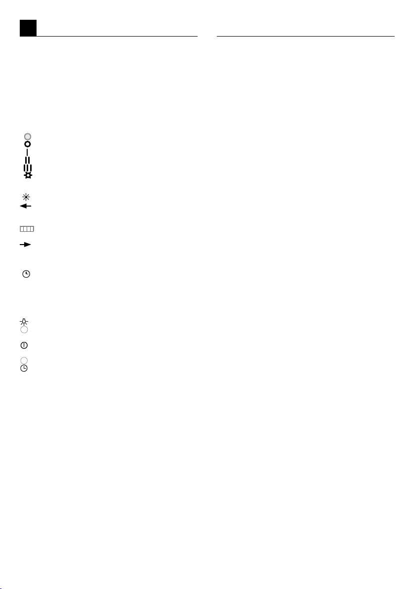
CONTROL PANEL
TYPE A (Fig.A)
- Pilot light
- Fan-off
- First speed (minimum)
- Second speed (medium)
- Third speed (maximum)
- Light ON/OFF
TYPE B (Fig.B)
- Light ON/OFF
- Switch on at 4th speed (maximum)
Speed reduction from 4th to 1st speed then
switch-off
-
Display - shows the set speed (from 1 to 4)
- Switch on at 1st speed (minimum). Intake
increase from 1st to 4th speed, then switch-
off.
- Timer - Activation of the auto switch-off timer
(10 minutes).
Remote Control (Fig.B1) optional
TYPE C (Fig.C)
- Light ON/OFF
- Reduce fan speed (4 to 1)
- ON/OFF.
Switch on the cooker hood at speed 1.
Switch off the cooker hood at any speed.
- Increase fan speed (1 to 4)
- TIMER - Activate the timer function.
The timer will automatically switch off the fan
after 15 minutes. When the fan speed is set
to 4 the timer activates automatically. After 15
minutes of activity the fan will automatically
switch to speed 3.
SAFETY INSTRUCTIONS
In certain circumstances electrical appliances
may be a danger hazard.
• The hood has been designed to remove the kitchen
smells; any other additional use shall be regarded
as non-intended.
• Areate the room if other appliances that are not
supplied by electrical power are being used while
the hood is on.
• Do not leave the cooker on if it is not being used.
• Do not ambé food directly under the cooker hood to
prevent the grease lter catching re due to ames.
• Constantly check food frying to avoid that the
overheated oil may become a re hazard.
• Do not check the status of the lters while the cooker
hood is operating.
• Do not touch the light bulbs after appliance use.
USE AND MAINTENANCE
It is recommended to switch on the appliance
before cooking. It is also recommended to leave
the appliance in operation for 10 minutes after
cooking is terminated in order to completely
eliminate cooking vapours and odours.
The proper function of the cooker hood is
conditioned by the regularity of the maintenance
operations, in particular, the active carbon lter.
Clean the fan and other surfaces of the cooker hood
regularly using a cloth moistened with denatured
alcohol or non abrasive liquid detergent.
WARNING: unplug the appliance or switch
off the circuit breaker before carrying out
maintenance operations.
METALLIC ANTI-GREASE FILTERS
- The lters must be washed at least once a month
with hot water and household detergent.
- They can also be washed in the dishwasher.
- To disassemble unscrew the xing screw in the
middle of the lter. (Fig. 1)
ACTIVATED CARBON FILTER (Fig. 2)
(Only ltering types) sold aside
- The lter cannot be regenerated, it must be re-
placed at least once every two months.
- For the substitution it is necessary to dismount
the central anti-grease metal lter, slide out the
modular lter from its housing situated inside the
cooker hood.
LIGHTING
In order to change the mounted lamps:
- rotate the light unit anti-clockwise;
- remove the light unit (Fig. 3).
- Replace the lamp with one that has the same fea-
tures because one with major power may cause
severe damage to the electrical system.
INSTALLING INSTRUCTIONS
GENERAL INFORMATION
This hood has been arranged to be installed above
a cooktop. It can be used in 2 ways:
•EXAUST MODE: the kitcken vapours are puried
by the metal anti-grease lters and carried outside
through a ducting system.
•RECIRCULATING MODE: the kitcken vapours
are puried by the metal anti-grease lters and
an activated carbon lter (sold separately), then
conveyed back into the kitchen.
We suggest to have installation carried out
by qualified personnel, in compliance with
all the current regulations and in particular
with the ones concerning air exhaust and
electrical connection.The manufacturer cannot
be held liable for damages caused by improper
installation or if it has not been carried out
according to the state-of-the-art.
EN
COMPONENTS (Fig.D)
A - Complete hood casing
B - Closing panel anchorage bracket
C - Rear closing panel
D - Box support bracket for wall
E - Reduction tting dia. 120/150
E - Deector (only for ltering types)
G - Upper stack wall clamp
(only for aspirating types)
H - Upper telescopic stack
I - Lower telescopic stack
L - Bag with accessories and screws
INSTALLATION
The appliance must be installed at a minimum
height of 650 mm from an electric cooker stove, or
750 mm from gas or combined cooker stoves.
If a connection tube composed of two parts is used,
the upper part must be placed outside the lower
part. Do not connect the cooker hood exhaust to
the same conductor used to circulate hot air or for
evacuating fumes from other appliances generated
by other than an electrical source.
Take care when the cooker hood is operating
simultaneously with an open replace or burner
that depend on the air in the environment and are
supplied by other than electrical energy, as the
cooker hood removes the air from the environment
which a burner or replace need for combustion.
The negative pressure in the environment must
not exceed 4 Pa (4x10 –5 bar). Provide adequate
ventilation in the environment for a safe operation
of the cooker hood. Follow the local laws applicable
for external air evacuation.
•HOW TO POSITION THE HOOD
plaster board wall:
- Mount the reduction connector 120/150 where the
discharge air pipe is a diameter of Ø125. (Fig. 4)
- Fix the anchorage bracket for the closing panel to
the cooker hood and lock into place the rear closing
panel; nally insert from beneath the two (2) xing
screws (Fig. 5).
The locking operation must be performed once the
cooker hood has been mounted.
- Securely hang the cooker hood body to the wall
using the 2 screws supplied M5 x 40 (Fig. 6),
always considering that the distance between the
cook top area and the cooker hood should not be
less than 65 cm.
- Fix the cooker hood to the wall on both sides using
the 4 screws (A/B). (Fig.6).
Attention: for the installation of the 2 shers (b) it
must remove the panel of closing of the hood.
corner:
- Fix the box support bracket to the wall using the 2
screws supplied. (Fig. 7)
- For the rest follow the instructions for mounting
as on plaster board wall for positioning the cooker
hood to the wall.
•HOW TO ASSEM BL E TH E OU TD OO R
SCAVENGING PIPE
- Preferably use a Ø150 or Ø125 tube, or possibly
exible, and x it with a hose clamp to the reduction
tting (Fig 8).
- Connect the scavenging pipe to the outdoor duct
and x it with a pipe-tightening ring.
•HOW TO POSITION THE UPPER STACK WALL
CLAMP (Fig.9)
(Only for aspirating types)
- Fix the upper replace anchoring rod at the height
desired, using the two supplied M5 x 40 screws.
•POSITIONING THE FILTER DEFLECTOR (Fig. 10)
(Only for lter version with carbon lter).
- Fix the ltering deector to the wall using the
screws supplied.
- Connect the Ø 150 air discharge tting of the hood
to the Ø 150 tting of the lter deector and relative
hose clamp.
•HOW TO POSITION THE STACKS:- Slide the
upper telescopic stack inside the lower telescopic
stack (Fig. 11).
- Position the lower telescopic stack on the hood
case.
- Raise the upper telescopic stack to the height
desired and x it by means of the two M3.9 x 9.5
screws included in the supply (Fig. 12).
ELECTRICAL CONNECTION
The appliance has been manufactured as a class II,
therefore no earth cable is necessary.
The connection to the mains is carried out as
follows:
BROWN = L line BLUE = N neutral
If not provided, connect a plug for the electrical load
indicated on the description label. Where a plug
is provided, the cooker hood must be installed in
order that the plug is easily accessible.
An omnipolar switch with a minimum aperture of
3 mm between contacts, in line with the electrical
load and local standards, must be placed between
the appliance and the network in the case of direct
connection to the electrical network.
OPERATING CHECKS
Check lights and motor start-up on all speeds.
DISPOSAL OF OLD ELECTRICAL APPLIANCES
The European Directive 2002/96/EC on Waste
Electrical and Electronic Equipment (WEEE),
requires that old household electrical
appliances must not be disposed of in the
normal unsorted municipal waste stream. Old
appliances must be collected separately in
order to optimise the recovery and recycling of the materials
they contain and reduce the impact on human health and
the environment.
The crossed-out dustbin symbol on the product reminds
you of your obligation regarding separated waste collection.
Consumers should contact their local public service or their
local dealer for more information on the correct disposal of
exhausted household appliances.
THE MANUFACTURER DECLINES ALL RESPONSIBILITY
FOR EVENTUAL DAMAGES CAUSED BY BREAKING
THE ABOVE WARNINGS. THE WARRANTY IS NOT
VALID IN THE CASE OF DAMAGE CAUSED BY FAILURE
TO COMPLY WITH THE ABOVE WARNINGS.THE
MANUFACTURER DECLINES ALL RESPONSIBILITY
FOR EVENTUAL DAMAGES CAUSED BY BREAKING
THE ABOVE WARNINGS.