Baumer DACU 820-2.0-500BS User manual

DACU_820_BA_V2_1M.doc 1/40 Baumer Electric AG
Frauenfeld, Switzerland
Betriebsanleitung
Ladungsverstärker
Instruction Manual
Charge Amplifier
DACU 820-2.0-500BS
Baumer Electric AG
P.O. Box
Hummelstrasse 17
CH-8501 Frauenfeld
http://www.baumer.com
Irrtum sowie Änderungen in Technik und Design
vorbehalten.
This Manual is subjected to change without notice.
DACU_820_BA_V2_1M.doc 2/40 Baumer Electric AG
Frauenfeld, Switzerland
INHALTSVERZEICHNIS
1Funktionsbeschreibung ...........................................................................................................................4
2Sicherheits- und Betriebshinweise .........................................................................................................4
2.1 Bestimmungsgemässer Gebrauch.......................................................................................................4
2.2 Inbetriebnahme ....................................................................................................................................4
2.3 Sicherheitshinweise .............................................................................................................................4
2.4 Transport und Lagerung.......................................................................................................................4
2.5 Organisatorische Massnahmen ...........................................................................................................5
3Montage......................................................................................................................................................5
4Funktion .....................................................................................................................................................6
4.1 Blockschaltbild .....................................................................................................................................6
4.2 Elektrische Anschlüsse ........................................................................................................................7
4.3 Ladungsbereiche..................................................................................................................................8
5Inbetriebnahme..........................................................................................................................................8
5.1 Steuerungsseitig anschliessen.............................................................................................................8
5.2 Sensorseitig anschliessen ...................................................................................................................8
5.3 Einstellung der Messbereiche..............................................................................................................9
5.4 Alarmausgänge .................................................................................................................................. 11
5.5 RESET – Funktion .............................................................................................................................11
5.6 PEAK – Funktion................................................................................................................................ 11
5.7 80% Test.............................................................................................................................................12
5.8 Polaritätsumschaltung........................................................................................................................12
5.9 Identifikation des Ladungsverstärkers ...............................................................................................12
6Serielle Schnittstelle ...............................................................................................................................13
6.1 Beschreibung .....................................................................................................................................13
6.2 Datenformat Master ...........................................................................................................................13
6.3 Datenformat Slave (DACU)................................................................................................................17
7Technische Daten....................................................................................................................................18
7.1 Elektrische Daten ...............................................................................................................................18
7.2 Mechanische Daten ...........................................................................................................................18
7.3 Umgebungsbedingungen...................................................................................................................18
7.4 Abmessungen ....................................................................................................................................19
8Zubehör....................................................................................................................................................19
9Service......................................................................................................................................................20

DACU_820_BA_V2_1M.doc 3/40 Baumer Electric AG
Frauenfeld, Switzerland
CONTENT
1Functional Description ...........................................................................................................................22
2Safety and operating notes....................................................................................................................22
2.1 Use as specified.................................................................................................................................22
2.2 Putting into operation .........................................................................................................................22
2.3 Safety notes .......................................................................................................................................22
2.4 Transport and storage........................................................................................................................22
2.5 Organizational actions .......................................................................................................................22
3Mounting ..................................................................................................................................................23
4Function ...................................................................................................................................................23
4.1 Block diagram ....................................................................................................................................23
4.2 Electrical connections ........................................................................................................................24
4.3 Measuring ranges ..............................................................................................................................25
5Start up.....................................................................................................................................................25
5.1 Connection on controller side ............................................................................................................25
5.2 Connecting on sensor side ................................................................................................................25
5.3 Setting the measurement ranges.......................................................................................................26
5.4 Alarm outputs .....................................................................................................................................28
5.5 RESET function..................................................................................................................................28
5.6 PEAK function ....................................................................................................................................28
5.7 80% test .............................................................................................................................................29
5.8 Change polarity..................................................................................................................................29
5.9 Identification of charge amplifier ........................................................................................................29
6Serial Interface.........................................................................................................................................30
6.1 Description .........................................................................................................................................30
6.2 Data format Master ............................................................................................................................30
6.3 Data format Slave (DACU).................................................................................................................34
7Technical data..........................................................................................................................................35
7.1 Electrical data.....................................................................................................................................35
7.2 Mechanical data .................................................................................................................................35
7.3 Ambient conditions.............................................................................................................................35
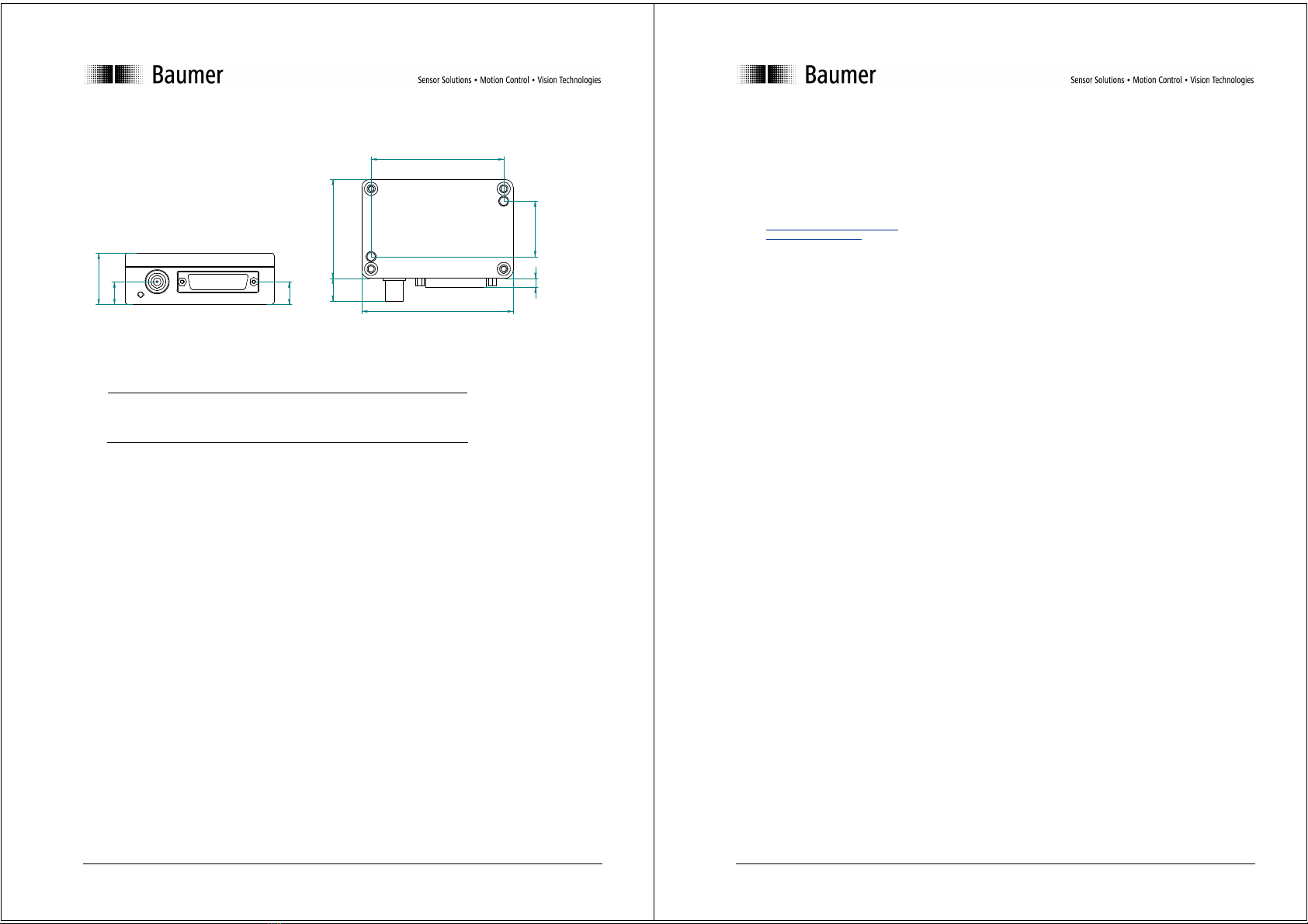
7.4 Dimensions ........................................................................................................................................36
8Accessories .............................................................................................................................................36
9Service......................................................................................................................................................37
DACU_820_BA_V2_1M.doc 4/40 Baumer Electric AG
Frauenfeld, Switzerland
1 Funktionsbeschreibung
Der DACU 820 ist ein Mehrbereichsladungsverstärker für den industriellen Einsatz. Er wandelt die
von einem piezoelektrischen Sensor abgegebene Ladung in zwei proportionale Spannungssignale
um, die in ihrer Empfindlichkeit separat eingestellt werden können. Dieser Ladungsverstärker eignet
sich somit in Verbindung mit einem hochempfindlichen Dehnungssensor sowohl zur
Schliesskraftmessung als auch zur gleichzeitigen Überwachung des Formschutzes ohne dass die
Ladungsbereiche umgeschaltet werden müssen.
Die wichtigsten Merkmale zusammengefasst:
• geringe Drift der Messkette durch abgeglichene Eingangsoffsetspannung
• robustes Aludruckguss-Gehäuse
• 3 fixe Bereiche von 100.000pC – 500.000pC (Kanal 1)
• 1 einstellbarer Bereich von 100.000pC – 500.000pC (Kanal 1)
• 4 fixe Bereiche von 2.000pC – 20.000pC (Kanal 2)
• Test-Funktion
• schneller Spitzenwertspeicher
• einstellbare Grenzwerte mit Schaltausgängen
• Versorgungsspannungsbereich von 10 bis 40V
• Serielle Schnittstelle RS 232
• Polaritätsumschaltung der Ausgangssignale
2 Sicherheits- und Betriebshinweise
2.1 Bestimmungsgemässer Gebrauch
• Der Ladungsverstärker darf ausschliesslich in den für ihn spezifizierten Leistungen betrieben
werden.
2.2 Inbetriebnahme
• Einbau und Montage des Ladungsverstärkers darf ausschliesslich durch eine Elektrofachkraft
erfolgen.
• Verdrahtungsarbeiten am Stecker oder im Schaltschrank dürfen nur in spannungslosen Zustand
durchgeführt werden.
• Betriebsanleitung des Maschinenherstellers beachten.
2.3 Sicherheitshinweise
• Vor Inbetriebnahme der Anlage alle elektrischen Verbindungen überprüfen.
• Wenn die Montage, das elektrische Anschliessen oder sonstige Arbeiten am Ladungsverstärker
nicht fachgerecht ausgeführt werden, kann es zu Fehlfunktionen oder Ausfall des
Ladungsverstärkers kommen.
• Eine Gefährdung von Personen, eine Beschädigung der Anlage und Betriebseinrichtungen durch
den Ausfall oder Fehlfunktion des Ladungsverstärkers muss durch geeignete
Sicherheitsmassnahmen ausgeschlossen werden.
• Der Ladungsverstärker darf nicht ausserhalb der Grenzwerte betrieben werden, welche in den
Technischen Daten (s. Kapitel 7 Technische Daten) angegeben sind.
Bei Nichtbeachtung der Sicherheitshinweise kann es zu Fehlfunktionen, Sach- und
Personenschäden kommen!
2.4 Transport und Lagerung
• Transport und Lagerung nur in Originalverpackung
• Ladungsverstärker nicht fallen lassen oder grösseren Erschütterungen aussetzen

DACU_820_BA_V2_1M.doc 5/40 Baumer Electric AG
Frauenfeld, Switzerland
2.5 Organisatorische Massnahmen
• Stellen Sie sicher, dass das Personal die Betriebsanleitung, und hier besonders das Kapitel
„Sicherheits- und Betriebshinweise“ gelesen und verstanden hat.
• Ergänzend zur Betriebsanleitung allgemeingültige gesetzliche und sonstige verbindliche
Regelungen zur Unfallverhütung und zum Umweltschutz beachten und sicherstellen.
3 Montage
Der Ladungsverstärker wird mit zwei rostfreien Befestigungsschrauben M4 geliefert. Das Gehäuse
muss für die Montage nicht geöffnet werden, da die Schrauben bereits eingelegt sind.
Die Masse für die Montagelöcher betragen 86 x 36mm (s. Kapitel 7.4
DACU_820_BA_V2_1M.doc 6/40 Baumer Electric AG
Frauenfeld, Switzerland
Abmessungen),
Gewindetiefe mindestens 8mm.
Die Schrauben können durch die Deckelbohrungen mit einem Inbusschlüssel (3mm) angezogen
werden, ggf. mit Loctite sichern.
Sollten längere Schrauben benötigt werden ist der Deckel aufzuschrauben. Neue Schrauben mit
Zahnscheibe einsetzen.
Anschluss der Stecker s. Kapitel 5 Inbetriebnahme.
Hinweise:
Aus EMV-Gründen empfehlen wir, die Montageplatte (Montageort) zu erden.
Der Ladungsverstärker kann in jeder beliebigen Lage montiert werden, bei vertikaler Anordnung ist
jedoch eine Montage mit nach unten abgehenden Steckern vorzuziehen.
4 Funktion
4.1 Blockschaltbild
uP
Gain
80%-Test
Offset
Charge CH 1
Out
10
Ω
1
14
Offset
adjust
(sealed) 10
Ω
2Peak
Out
Signal
GND
Case
=
=
11
24
12
13
5
6
7
25
8
20
21
19
L1
20kHz
Com
Logik
Input
80%
Test
Operate
Range
A0
Range
A1
Range
B0
Range
B1
Code
Supply +
Code 0
Code 1
Code 2
9,22
4
15
16
10 +5V
- 12V
+12V
3
Com
Logik
Output
Alarm 0
Alarm 1
Level 0
Level 1
L0
Range
var.
Reset
Block diagram
DACU 820
Supply
GND
Supply
+
Gain
80%-Test
Offset
CH2
Out
10
Ω
23
20kHz
DIP-1
polarity
change
18
17
TX
RX
RS232
TTL
+-
+-
DIP-2
polarity
change
DIP-3
GW-1
DIP-4
GW-2

DACU_820_BA_V2_1M.doc 7/40 Baumer Electric AG
Frauenfeld, Switzerland
4.2 Elektrische Anschlüsse
Elektrische Anschlüsse D-Sub 25
Pin Funktion Aderfarbe nach DIN47100
1 Signal out CH1 weiss
2 Peak out braun
3 Level 1 (In or Out) grün
4 Level 0 (In or Out) gelb
5 Range B1 (CH2) grau
6 Range B0 (CH2) rosa
7 Range A1 (CH1) blau
8 Range A0 (CH1) rot
9 Supply GND schwarz
10 + Supply violett
11 Code 2 grau-rosa
12 Code 0 rot-blau
13 Code Supply + weiss-grün
14 Signal GND braun-grün
15 Alarm 1 (CH1) weiss-gelb
16 Alarm 0 (CH1) gelb-braun
17 RX weiss-grau
18 TX grau-braun
19 Com Logic Input weiss-rosa
20 Operate rosa-braun
21 80% Test weiss-blau
22 Supply GND braun-blau
23 Signal out CH2 weiss-rot
24 Code 1 braun-rot
25 Com Logic Output (Alarm) weiss-schwarz
DACU_820_BA_V2_1M.doc 8/40 Baumer Electric AG
Frauenfeld, Switzerland
4.3 Ladungsbereiche
Wahl der Messbereiche
Range CH1 Messbereich
A1 A0
pC/10V
1 0 0
500’000
2 0 1
200’000
3 1 0
100’000
4 1 1
100’000...500’000
Range CH2
B1 B0
5 0 0
20’000
6 0 1
10’000
7 1 0
5’000
8 1 1
2’000
5 Inbetriebnahme
5.1 Steuerungsseitig anschliessen
Die Ein- und Ausgänge sind galvanisch getrennt und können sowohl als positive als auch als negative
Logik geschaltet werden. Die Eingänge haben den gemeinsamen Anschluss an Pin 19 – Com Logic
Input, die beiden Schaltausgänge an Pin 25 – Com Logic Output.
Beispiele für das Operate Signal:
DACU
D-Sub
Maschinen-
steuerung
SV
s
20 Operate
19 Com Logic Input
Positive Logik, Operate aktiv bei geschlossenem Schalter S
DACU
D-Sub
Maschinen-
steuerung
S
V
s
20 Operate
19 Com Logic Input
Negative Logik, Operate aktiv bei geschlossenem Schalter S
Hinweis:
Wenn während dem Betrieb keine Umschaltung der Ladungsbereiche erfolgen muss, können die
benötigten Range-Eingänge mit der Speisespannung fix verbunden werden. Der Com Logic Input wird
dann mit dem Supply GND verbunden.
5.2 Sensorseitig anschliessen
Für den Anschluss eines Sensors müssen grundsätzlich hochisolierende Kabel verwendet werden.
Schliessen sie den Sensor vor dem Anschliessen nach Möglichkeit kurz, denn piezoelektrische
Sensoren können hohe Spannungen erzeugen. Diese könnten die Elektronik des Ladungsverstärkers
beschädigen. Vermeiden Sie es die Isolation der BNC - Stecker zu berühren und achten Sie darauf,
dass kein Staub und keine Feuchtigkeit eindringen kann. Durch Feuchtigkeit und sonstige
Verschmutzung wird die Isolation vermindert, dies kann zu erhöhter Drift führen.

DACU_820_BA_V2_1M.doc 9/40 Baumer Electric AG
Frauenfeld, Switzerland
5.3 Einstellung der Messbereiche
Die beiden Messbereiche werden über die vier Range-Eingänge angewählt (Anschluss s. Kapitel 5.1
Steuerungsseitig anschliessen).
5.3.1 Fixe Bereiche
Es stehen 3 fixe Bereiche von 100’000pC bis 500’000pC für Kanal 1 und 4 fixe von 2’000pC bis
20’000pC für Kanal 2 zu Verfügung. Wählen Sie je nach zu erwartender Ladung den passenden
Messbereich aus.
Beispiel:
Es soll die Schliesskraft mit einem Piezoelektrischen Dehnungssensor gemessen werden.
-Empfindlichkeit Sensor: -920pC/µε
-max. Schliesskraft 400kN Dehnung an der Messstelle: 180µε
Die max. Ladung berechnet sich: pC
pC
Q165600180920
max −=∗−=
µε
µε
gewählter Messbereich (-)200.000pC/10V
Eingang Range A0 (Pin 8) auf high setzen (bei pos. Logik)
Die Ausgangspannung beträgt dann bei 400kN: VV
pC
pC
UCH 28.810
200000
165600
1=∗
−
−
=
Bemerkung
Der andere Range-Eingang A1 muss nicht beschaltet werden!
Die maximal tolerierte Kraft für den Formschutz wird mit 0.5%FS = 2kN festgesetzt.
die Dehnung wird dann 0.9µε betragen (0.5% von 180µε)
Der Sensor liefert ein Ausgangssignal von: pC
pC
QS8289.0920 −=∗−=
µε
µε
gewählter Messbereich: 2.000pC/10V
Eingang Range B1 und B0 (Pin 5 und 6) auf high setzen (bei pos. Logik)
Der Pegel für die Formschutzüberwachung (Maschinensteuerung) ist dann auf:
VV
pC
pC
UCH 14.410
2000
828
2=∗
−
−
= einzustellen
DACU_820_BA_V2_1M.doc 10/40 Baumer Electric AG
Frauenfeld, Switzerland
5.3.2 Variabler Bereich
Mit dem variablen Bereich kann die Messkette bei bekannter Messgrösse auf ein beliebiges
Ausgangssignal abgeglichen werden. Nehmen Sie die Anlage in Betrieb und stellen sie das
Ausgangssignal auf den gewünschten Spannungswert mit dem Range-Poti ein.
Dazu muss der Deckel des Ladungsverstärkers geöffnet werden.
Range
L0
L1
Anordnung der Poti und DIP-Schalter
Beispiel:
Die Messkette soll bei maximaler Kraft auf eine Ausgangsspannung von 8V abgeglichen
werden.
Die Ladung des Sensors darf bei maximaler Kraft höchstens 500’000pC betragen.
Eingang Range A1 und A0 (Pin 7 und 8) auf high setzen (bei pos. Logik)
Anlage in Betrieb nehmen und bei maximaler Kraft mit dem Range-Poti die Ausgangspannung
auf 8V abgleichen.
Wichtiger Hinweis:
Der Ladungsverstärker muss nach der letzten Justage des variablen Bereichs noch mind.
5min in Betrieb sein. Erst dann wird die Einstellung im nichtflüchtigen Speicher übernommen.
O
N
1
2
3
4

DACU_820_BA_V2_1M.doc 11/40 Baumer Electric AG
Frauenfeld, Switzerland
5.4 Alarmausgänge
Die beiden Alarmausgänge überwachen das Ausgangssignal von Kanal 1 oder Kanal 2 und können
zur Signalisierung von Grenzwerten oder zur Definition von Messfenstern eingesetzt werden. Die
Schwellspannung von 0 – 10V kann auf zwei Arten eingestellt werden:
1. Die Schwellspannung wird über den Eingang an Pin 3 bzw. 4 extern eingespeist
oder
2. sie wird nach Öffnen des Deckels mit den beiden Poti L0 und L1 (s. Bild 5.3.2) eingestellt. Die
eingestellte Spannung kann an Pin 3 bzw. 4 gemessen werden.
Kanalselektion:
Die beiden Alarmausgänge können über DIP-Schalter wie folgt den jeweiligen Kanälen (K1, K2)
zugeordnet werden:
DIP 3 DIP 4
ON GW 1 K1 GW 2 K1
OFF GW 1 K2 GW 2 K2
Beide Alarmausgänge schliessen den Kontakt sobald der jeweils eingestellte Schwellwert
überschritten ist und bleiben bis zum nächsten Reset gesetzt.
Bemerkung:
Als Schaltelemente dienen zwei Photo-Mos Relais. Die Ausgänge sind galvanisch getrennt und für AC
und DC geeignet. Sie sind aber nicht kurzschlussfest und dürfen nicht jenseits der Spezifikation
betrieben werden. Bei einem Defekt sind die Photo-Mos Relais jedoch schnell austauschbar
(gesockelt).
5.5 RESET – Funktion
Durch die endlichen Isolationswiderstände der Sensoren, Kabel und der elektronischen Komponenten
geht ein Teil der vom Sensor abgegebene Ladung verloren. Das bedeutet, dass bei konstanter
physikalischer Messgrösse (z.B. Kraft) sich das Ausgangssignal in positiver oder negativer Richtung
verändert. Durch diese „Drift“ können statische Messungen nur bedingt bzw. über kurze Zeiträume
durchgeführt werden. Es ist deshalb notwendig den Ladungsverstärker zyklisch zu resetieren.
Der Ladungsverstärker wird über den Operate – Eingang aktiv geschaltet
Bemerkung:
Der Ladungsverstärker sollte immer auf „Reset“ geschaltet sein wenn kein Messergebnis benötigt
wird.
5.6 PEAK – Funktion
Die Peak - Funktion liefert für die Dauer eines Messzyklus den Maximalwert des Ausgangssignals
von Kanal 1. Sie wird mit dem Steuereingang Operate automatisch zurückgesetzt.
DACU_820_BA_V2_1M.doc 12/40 Baumer Electric AG
Frauenfeld, Switzerland
t
t
Operate
+10V
1
0
-10V Signal out CH1
Peak out
5.7 80% Test
Diese Funktion ermöglicht die Überprüfung der Messkette ohne dass ein Sensor angeschlossen ist
und kann somit für die Fehlereingrenzung genutzt werden. Die Amplitude beträgt ca. 8V (80%FS) an
beiden Kanälen.
Beispiel:
t
t
t
Operate
+8V
1
1
0
0
-8V
80%-Test
Signal out
CH1=CH2
5.8 Polaritätsumschaltung
Sollten die Ausgangssignale des Ladungsverstärkers nicht die gewünschte Polarität haben, kann
diese mit den jeweiligen DIP-Schaltern (DIP-1 Kanal 1, DIP-2 Kanal 2) gekehrt werden.
5.9 Identifikation des Ladungsverstärkers
Der Ladungsverstärker kann anhand eines Codes am Anschlussstecker identifiziert werden. Dazu
muss an Pin 13 eine definierte Spannung angelegt werden.
An den Pins 11,12 und 24 kann der Code ausgelesen werden, der diesem Typ entspricht.
Code für DACU 820:
Code 2 Code 1 Code 0
Pegel 0 1 0
Bedeutung: 0 Supply GND
1 Code Supply +

DACU_820_BA_V2_1M.doc 13/40 Baumer Electric AG
Frauenfeld, Switzerland
6 Serielle Schnittstelle
6.1 Beschreibung
Der DACU 820 ist mit einer seriellen Schnittstelle RS232 ausgerüstet. Darüber können mit den
entsprechenden Befehlen alle Funktionen eingestellt und die Messwerte der Analogausgänge (CH1
und CH2) ausgelesen werden.
Übertragungsformat
Die Informationen werden seriell über den Bus gesendet. Dabei gilt folgendes Format:
• 1 Start-Bit
• 8 Daten-Bits (das niederwertigste zuerst)
• 1 Stop-Bit
• Übertragungsgeschwindigkeit: 9’600 Baud (Default) – 115’200 Baud
Somit ergeben sich 10 Bit pro übertragenem Zeichen.
6.2 Datenformat Master
6.2.1 Allgemein
Der Befehl beginnt mit einem Startzeichen STX (02h), gefolgt vom Befehl und einer festen Anzahl
von Parametern und einer abschliessenden Checksumme. Der DACU gibt nach erfolgreicher
Überprüfung der Checksumme und der Ausführung des Befehls ein ACK (06h) an den Master
zurück.
Jede vom Master gesendete Botschaft hat folgendes Format:
ASCII ASCII ASCII ASCII
Startzeichen Befehl n-Parameter Checksumme
Checksumme: Summe aller ASCII-Zeichen, immer 1Byte lang (niederwertigste 4 Bit in ASCII
gewandelt).
6.2.2 Remote Funktion
Schaltet den Verstärker auf Remotebetrieb, oder wieder zurück. Im Remotebetrieb haben alle
Steuersignale (Operate, Range, Test) keinen Einfluss mehr.
Nach einem Stromunterbruch bzw. nach dem Einschalten ist die Remotefunktion inaktiv.
Der DACU lädt nach der Reaktivierung alle gespeicherten Einstellungen aus dem E2Prom.
Befehls-Datenstruktur:
Beispiel: Remote aktiv
Start Befehl Parameter Checksumme
02h 61h 31h 34h
STX a 1 4 (94h)
Parameter 0: Remote inaktiv, Steuerung über die Sub-D Leitungen
1: Remote aktiv, Steuerung über RS232
Achtung
Die Schnittstelle ist nach jedem Einschalten des DACU immer auf 9’600 Baud gesetzt!
Die Baudrate kann wie unter 6.2.9 beschrieben eingestellt werden.
DACU_820_BA_V2_1M.doc 14/40 Baumer Electric AG
Frauenfeld, Switzerland
6.2.3 Operate, Reset
Schaltet den Verstärker auf Reset bzw. Operate.
Befehls-Datenstruktur:
Start Befehl Parameter Checksumme
02h 62h 31h 35h
STX b 1 5 (95h)
Parameter 0: Reset
1: Operate
6.2.4 Range fixe Bereiche
Schaltet den Verstärker in einen fixen Bereich.
Befehls-Datenstruktur:
Beispiel: CH2 auf 10’000pC
Start Befehl P. 1 P. 2 P. 3 Checksumme
02h 63h 31h 30h 37h 44h
STX c 1 0 7 D(FDh)
Parameter 1 0: CH1
1 CH2
Parameter 2 & 3 02: Range 2 500'000 pC
CH1
03: Range 3 200'000 pC
CH1
04: Range 4 100'000 pC
CH1
06: Range 6 20'000 pC
CH2
07: Range 7 10'000 pC
CH2
08: Range 8 5'000 pC
CH2
09: Range 9 2'000 pC
CH2
6.2.5 Range variabler Bereich
Schaltet CH1 des Verstärkers in einen variablen Bereich zwischen 100’000pC und 500’000pC
Befehls-Datenstruktur:
Beispiel: 230’000pC
Start Befehl P. 1 P. 2 P. 3 P. 4 P. 5 P. 6 P. 7 Checksumme
02h 64h 30h 32h 33h 30h 30h 30h 30h 42h
STX d 0 2 3 0 0 0 0 B (1BBh)
Parameter 1 0: CH1
Parameter 2 - 7 Zahlenwerte im ASCII-Format

DACU_820_BA_V2_1M.doc 15/40 Baumer Electric AG
Frauenfeld, Switzerland
6.2.6 Alarmausgänge
Stellt den Level ein, bei dem eine Umschaltung erfolgt.
Befehls-Datenstruktur:
Beispiel: Alarm 2 auf (0)8’500mV
Start Befehl
P. 1 P. 2 P. 3 P. 4 P. 5 P. 6 Checksumme
02h 65h 31h 30h 38h 35h 30h 30h 35h
STX e 1 0 8 5 0 0 5 (195h)
Parameter 1 0: Alarm 1
1: Alarm 2
Parameter 2 - 6 Zahlenwerte im ASCII-Format
6.2.7 80% Test
Testfunktion, bei welcher der Ladungsverstärker ca. 8V ausgibt
Befehls-Datenstruktur:
Beispiel: Test on
Start Befehl
P. 1 Checksumme
02h 66h 31h 39h
STX f 1 9 (99h)
Parameter 1 0: Test off
1: Test on
6.2.8 Signal
Fragt den aktuellen Messwert ab.
Befehls-Datenstruktur:
Start Befehl
P. 1 Checksumme
02h 67h 31h 41h
STX g 1 A (9Ah)
Parameter 1 0: Ausgabe eines Messwertes CH1
1: Kontinuierliche Ausgabe der Messwerte CH1
2 Ausgabe eines Messwertes CH2
3 Kontinuierliche Ausgabe der Messwerte CH2
Bemerkung:
Die kontinuierliche Ausgabe muss mit der Abfrage eines Einzelwertes beendet werden!
(Parameter 1 = 0 oder 2)
DACU_820_BA_V2_1M.doc 16/40 Baumer Electric AG
Frauenfeld, Switzerland
6.2.9 Übertragungsrate
Konfiguriert die Schnittstelle auf die entsprechende Übertragungsrate.
Der DACU gibt auf der vorherigen Übertragungsrate ein ACK (06h) zurück und wechselt dann auf
die neue Einstellung.
Befehls-Datenstruktur:
Beispiel: 38’400Baud
Start Befehl
P. 1 Checksumme
02h 68h 37h 31h
STX h 7 1 (A1h)
Parameter 1 5: 9'600 (default)
6: 19’200
7: 38’400
8: 57’600
9: 115’200
Übertragung der Messwerte:
Baud Abtastfrequenz
[Hz]
Zeitfenster
[ms]
9k6 40 25
19k2 50 20
38k4 50 20
57k6 100 10
115k2 200 5
6.2.10 Einstellungen speichern
Speichert folgende Werte im E2Prom.
• Fixe Bereiche von CH1 und CH2 oder variabler Bereich
• Level der Alarmausgänge
Diese werden nach dem aktivieren wieder eingelesen ( 6.2.2).
Befehls-Datenstruktur:
Start Befehl
P. 1 Checksumme
02h 73h 30h 35h
STX s 0 5 (A5h)
Parameter 1 0: Immer 0

DACU_820_BA_V2_1M.doc 17/40 Baumer Electric AG
Frauenfeld, Switzerland
6.3 Datenformat Slave (DACU)
6.3.1 Messwerte
Gibt den aktuellen Messwert an den Master aus. Die Messwerte werden als Hex-Zahl ausgegeben.
Negative Werte als 2er-Komplement. Als Startwert dient die Kanalkennung a bzw. b.
Checksumme: Summe aller Hex-Werte, immer 1Byte lang als ASCII-Zeichen
Antwort-Datenstruktur:
P. 1 P. 2 P. 3 P. 4 P. 5 Checksumme
Parameter 1 a: Messwerte CH1
b Messwerte CH2
Parameter 2 - 5 Messwert als Hex Zahl
Beispiel 1:
Messwert: 7685mV an CH1
Hex: 1E05h, Checksumme 13C
P. 1 P. 2 P. 3 P. 4 P. 5 Checksumme
61h 31h 45h 30h 35h 43h
a 1 E 0 5 C (13Ch)
Beispiel 2:
Messwert -300mV an CH2
Hex: FED4h, Checksumme 165h
P. 1 P. 2 P. 3 P. 4 P. 5 Checksumme
62h 46h 45h 44h 34h 35h
b F E D 4 5 (165h)
DACU_820_BA_V2_1M.doc 18/40 Baumer Electric AG
Frauenfeld, Switzerland
7 Technische Daten
7.1 Elektrische Daten
Spannungsversorgung 10...40VDC
Leistungsaufnahme < 1.5W (1)
Messbereich Kanal 1 ± 100’000..500’000pC
Messbereich Kanal 2 ± 2’000..20’000pC
Ausgangssignal ± 10V
Genauigkeit <± 1%FS
Linearität < 0.02%FS
Ausgangsoffset <± 5mV
Störspannung < 5mVpp (0.1Hz..100kHz) (2)
Ausgangswiderstand 10Ω
Reset Operate Sprung <± 10mV
Drift < 0.03pC/s bei 23°C (3)
Offsetspannung Q-Eingang <50µV
Frequenzgang (-3dB) 0..20kHz
Steuereingänge ± 5V.. ± 45V, galv. getrennt
Schaltausgänge
max. 45V
max. 100mA
galv. getrennt
1) < 55mA bei 24V
2) <20mVpp im 2000pC Bereich
3) Geltungsbereich: Ladungseingang offen und abgeschirmt, DACU für min. 30min an der
Betriebsspannung angeschlossen,
RESET aktiv, Deckel fest geschlossen.
7.2 Mechanische Daten
Anschluss Steuerungsseitig D-Sub 25-Pol, male
Anschluss Sensor BNC
7.3 Umgebungsbedingungen
Betriebstemperatur -5...+60°C
Lagertemperatur -20...+80°C
Schutzart IP 40
EMV EN 61000-6-2 Immunität
EN 61000-6-4 Emission

DACU_820_BA_V2_1M.doc 19/40 Baumer Electric AG
Frauenfeld, Switzerland
7.4 Abmessungen
34
15
15
64
6
15
98
36
86
8 Zubehör
Bestellbezeichnung
Anschlusskabel 5m,
D-Sub 25 female,
anderes Ende offen
(Aderfarben siehe Kapitel 4.2)
DZCS 05/DACU 8
Weiteres Zubehör auf Anfrage.
DACU_820_BA_V2_1M.doc 20/40 Baumer Electric AG
Frauenfeld, Switzerland
9 Service
Unsere Verkaufs- und Beratungsteams stehen Ihnen gerne zur Verfügung.
Baumer Electric AG
P.O. Box
Hummelstrasse 17
CH-8501 Frauenfeld
Tel. +41 (0)52 728 11 22
Fax +41 (0)52 728 13 95
www.baumer.com

DACU_820_BA_V2_1M.doc 21/40 Baumer Electric AG
Frauenfeld, Switzerland
DACU_820_BA_V2_1M.doc 22/40 Baumer Electric AG
Frauenfeld, Switzerland
1 Functional Description
The DACU 820 is a multi-range charge amplifier for industrial use. It converts the charge which is
output by one piezo-electric sensor into two proportional voltage signals. The measuring range of both
output signals can be set separately. The DACU 820 is especially suitable in combination with the
high resolution strain sensor DSPN. Clamping force measurement and mold protection on injection
molding machines can be realized contemporaneously without switching the measuring range. Here
the most important features:
• small drift of measuring chain because of compensated input offset voltage
• robust die cast aluminum housing
• 3 fix ranges 100.000pC – 500.000pC (Channel 1)
• 1 adjustable range 100.000pC – 500.000pC (Channel 1)
• 4 fix ranges 2.000pC – 20.000pC (Channel 2)
• test function
• peak value memory
• adjustable limits with switching outputs
• RS232 Interface
• Supply voltage range 10 to 40V
• Polarity change-over of the output signals
2 Safety and operating notes
2.1 Use as specified
• The charge amplifier must be operated exclusively at the specified purposes.
2.2 Putting into operation
• The charge amplifier must be mounted only by a qualified electrician.
• Wiring on the plug or in the control cabinet must be carried out only in the off-power state.
• Follow the machine manufacturer's instructions.
2.3 Safety notes
• Before the system is put into operation, check all electrical connections.
• If the mounting, electrical connection or other work on the charge amplifier is not carried out
correctly, wrong functioning or failure of the charge amplifier may result.
• Danger to personnel and damage to the system and operating equipment because of failure or
wrong functioning of the charge amplifier must be excluded by suitable safety actions.
• The charge amplifier must not be operated outside the limits which are given in the Technical
Data (see Section 7 Technical Data).
Failure to observe the safety notes can result in wrong functioning and material and
personal damage!
2.4 Transport and storage
• Transport and storage only in original packing
• Do not let the charge amplifier fall or allow it to be shaken vigorously
2.5 Organizational actions
• Ensure that the personnel have read and understood the operating instructions, particularly the
section "Safety and operating notes".
• In addition to the operating instructions, generally applicable legal and other binding regulations
for accident prevention and environmental protection must be reliably observed.

DACU_820_BA_V2_1M.doc 23/40 Baumer Electric AG
Frauenfeld, Switzerland
3 Mounting
The charge amplifier is supplied with two stainless mounting screws M4. The housing does not have
to be opened for mounting, because the screws are already inserted.
The dimensions of the mounting holes are 86 x 36mm (see Section 7.4), minimum thread depth 8mm.
The screws can be tightened through the holes in the lid using an hex wrench (3mm), and secured
with Loctite if necessary.
If longer screws are required, the lid must be unscrewed. Insert new screws with tooth lock washer.
For connecting the plug, see Section 5 Start up.
Notes:
For EMC reasons, we recommend to connect the mounting plate to earth (mounting position).
The charge amplifier can be fitted in any position, but if it is arranged vertically, mounting with plugs
pointing downward is preferred.
4 Function
4.1 Block diagram
uP
Gain
80%-Test
Offset
Charge CH 1
Out
10
Ω
1
14
Offset
adjust
(sealed) 10
Ω
2Peak
Out
Signal
GND
Case
=
=
11
24
12
13
5
6
7
25
8
20
21
19
L1
20kHz
Com
Logik
Input
80%
Test
Operate
Range
A0
Range
A1
Range
B0
Range
B1
Code
Supply +
Code 0
Code 1
Code 2
9,22
4
15
16
10 +5V
- 12V
+12V
3
Com
Logik
Output
Alarm 0
Alarm 1
Level 0
Level 1
L0
Range
var.
Reset
Block diagram
DACU 820
Supply
GND
Supply
+
Gain
80%-Test
Offset
CH2
Out
10
Ω
23
20kHz
DIP-1
polarity
change
18
17
TX
RX
RS232
TTL
+-
+-
DIP-2
polarity
change
DIP-3
GW-1
DIP-4
GW-2
DACU_820_BA_V2_1M.doc 24/40 Baumer Electric AG
Frauenfeld, Switzerland
4.2 Electrical connections
Electrical connections D-Sub 25
Pin Function Leads color DIN47100
1 Signal out CH1 white
2 Peak out brown
3 Level 1 (In or Out) green
4 Level 0 (In or Out) yellow
5 Range B1 (CH2) gray
6 Range B0 (CH2) pink
7 Range A1 (CH1) blue
8 Range A0 (CH1) red
9 Supply GND black
10 + Supply violet
11 Code 2 gray-pink
12 Code 0 red-blue
13 Code Supply + white-green
14 Signal GND brown-green
15 Alarm 1 (CH1) white-yellow
16 Alarm 0 (CH1) yellow-brown
17 RX white-gray
18 TX gray-brown
19 Com Logic Input white-pink
20 Operate pink-brown
21 80% Test white-blue
22 Supply GND brown-blue
23 Signal out CH2 white-red
24 Code 1 brown-red
25 Com Logic Output (Alarm) white-black

DACU_820_BA_V2_1M.doc 25/40 Baumer Electric AG
Frauenfeld, Switzerland
4.3 Measuring ranges
Choice of measuring range
Range CH1 measuring range
A1 A0
pC/10V
1 0 0
500’000
2 0 1
200’000
3 1 0
100’000
4 1 1
100’000...500’000
Range CH2
B1 B0
5 0 0
20’000
6 0 1
10’000
7 1 0
5’000
8 1 1
2’000
5 Start up
5.1 Connection on controller side
The inputs and outputs are galvanically separated and can be connected as both positive and negative
logic. The inputs have the common connection on pin 19 – Com Logic Input. The two outputs are on
pin 25 – Com Logic Output.
Examples of the Operate Signal:
DACU
D-Sub
machine controller
SV
s
20 Operate
19 Com Logic Input
positive logic, operate aktiv with closed switch S
DACU
D-Sub
machine
controller
S
V
s
20 Operate
19 Com Logic Input
negative logic, operate active with closed switch S
Note:
If no change of charge range has to take place during operation, the required range inputs can be
permanently connected to the supply voltage. The Com Logic Input is then connected to the Supply
GND.
5.2 Connecting on sensor side
To connect a sensor, high-insulation cables must always be used. If possible, short-circuit the sensor
before connecting it, because piezo-electric sensors can generate high voltages, which could damage
the electronics of the charge amplifier. Avoid touching the insulation of the BNC plug, and ensure that
no dust or humidity can penetrate it. Humidity and other contamination reduce the insulation, and can
cause increased drift.
DACU_820_BA_V2_1M.doc 26/40 Baumer Electric AG
Frauenfeld, Switzerland
5.3 Setting the measurement ranges
The measurement ranges are selected via the four range inputs (for connection see Section 5.1
Connecting on controller side).
5.3.1 Fix ranges
3 fix ranges from 100’000pC to 500,000pC for channel 1 and 4 fix ranges from 2’000pC to 20’000pC
for channel 2 are available. Select the suitable measurement range according to the expected
charge.
Example:
The intention is to measure a clamping force using a piezo-electric strain sensor.
-Sensor sensitivity: -920pC/µε
-max. clamping force 400kN strain on the measuring spot: 180µε
The maximum charge is calculated as: pC
pC
Q165600180920
max −=∗−=
µε
µε
chosen measurement range (-)200.000pC/10V
Set Range A0 (Pin 8) input to high (with positive logic)
Output voltage at 400kN: VV
pC
pC
UCH 28.810
200000
165600
1=∗
−
−
=
Comment
The other range input A1 must not be connected!
The maximum specified force for the mold protection is 0.5% = 2
die strain will have a value of 0.9µε (0.5% of 180µε)
The sensor has an output signal of: pC
pC
QS8289.0920 −=∗−=
µε
µε
choose measuring range: 2.000pC/10V
Input Range B1 und B0 (Pin 5 und 6) set on high (with pos. Logic)
the level for the mold protection should be set as follows:
VV
pC
pC
UCH 14.410
2000
828
2=∗
−
−
=

DACU_820_BA_V2_1M.doc 27/40 Baumer Electric AG
Frauenfeld, Switzerland
5.3.2 Variable range
With the variable range, the measuring chain can be adjusted for any output signal with a known
measured magnitude. Select the suitable measurement range according to the charge to be
expected. Now put the system into operation and set the output signal to the desired voltage value
using the range potentiometer.
To do this, the lid of the charge amplifier must be opened.
Range
L0
L1
Arrangement of potentiometer and DIP-switches
Example:
The measuring chain should be adjusted for a maximum force to an output voltage of 8V
Charge of sensor for maximum force: 500.000pC.
Input Range A1 and A0 (Pin 7 and 8) set on high (with pos. Logic)
Put the system into operation and set the output signal to 8V using the range potentiometer for
maximum force.
Important note:
The charge amplifier has to be in operational mode for five minutes after adjustment of the
variable range. After this time the setting is stored in the non-volatile memory.
O
N
1
2
3
4
DACU_820_BA_V2_1M.doc 28/40 Baumer Electric AG
Frauenfeld, Switzerland
5.4 Alarm outputs
The two alarm outputs monitor the output signal of channel 1, and can be used to signal limits or to
define measurement windows. The threshold voltage of 0 – 10V can be set in two ways:
3. The threshold voltage is fed in externally via the input on pin 3 or 4
or
4. It is set after the lid is opened, using the two potentiometers L0 and L1 (see Fig. 5.3.2). The set
voltage can be measured on pin 3 or 4.
Both alarm outputs close the contact as soon as the set threshold value is exceeded, and remain set
until the next reset.
Channel selection:
Both alarm outputs can be assigned to one of the two analog outputs (CH1, CH2) by a DIP-switch:
DIP 3 DIP 4
ON TH 1 CH1 TH 2 CH 1
OFF TH 1 CH 2 TH 2 CH 2
Comment:
Two Photo-Mos relays are used as circuit elements. The outputs are galvanically separated and
suitable for AC and DC. However, they are not short-circuit-proof and must not be operated beyond the
specification. However, the Photo-Mos relays can be replaced quickly in the case of a defect
(socketed).
5.5 RESET function
Because of the finite insulation resistances of the sensors, cables and electronic components, part of
the charge which the sensor outputs is lost. This means that with a constant physical measured
magnitude (e.g. force), the output signal changes in the positive or negative direction. Because of this
"drift“, static measurements can only be carried out to a limited extent or over short periods. It is
therefore necessary to reset the charge amplifier cyclically.
The charge amplifier is switched active via the Operate input.
Comment:
The charge amplifier should always be switched to "Reset“ if no measurement result is required.
5.6 PEAK function
For the duration of one measurement cycle, the peak function supplies the maximum value of the
output signal of Channel 1. It is reset automatically using the control input Operate.
t
t
Operate
+10V
1
0
-10V Signal out CH1
Peak out

DACU_820_BA_V2_1M.doc 29/40 Baumer Electric AG
Frauenfeld, Switzerland
5.7 80% test
This function makes it possible to check the measuring chain without a sensor being connected, and
can thus be used to limit errors. The amplitude is approx. 8V (80%FS).
Example:
t
t
t
Operate
+8V
1
1
0
0
-8V
80%-Test
Signal out
CH1=CH2
5.8 Change polarity
If the polarity of the output channel is not as favored it can be changed by the DIP-switch
(DIP-1 channel 1, DIP-2 channel 2).
5.9 Identification of charge amplifier
The charge amplifier can be identified on the basis of a code on the connecting plug. For this purpose,
a defined voltage must be applied to pin 13.
On pins 11, 12 and 24, the code corresponding to this type can be read out.
Code for DACU 820:
Code 2 Code 1 Code 0
Level 0 1 0
Meaning: 0 Supply GND
1 Code Supply +
DACU_820_BA_V2_1M.doc 30/40 Baumer Electric AG
Frauenfeld, Switzerland
6 Serial Interface
6.1 Description
The DACU 820 has an implemented serial interface RS232. With the corresponding commands it is
possible to set the Charge Amplifier and to read out the output signals (CH1 und CH2).
Transmission format
The Information are transmitted serially with following format:
• 1 Start-Bit
• 8 Data-Bits (the low order first)
• 1 Stop-Bit
• Transmission rate: 9’600 Baud (Default) – 115’200 Baud
That results 10 bit per transmitted character.
6.2 Data format Master
6.2.1 General
The command starts with the character STX (02h), followed by a command and a fix number of
parameters and finally a checksum. After checking the checksum and the execution of the
command, the DACU returns an ACK (06h) back to the master.
The message of the master has always following format:
ASCII ASCII ASCII ASCII
Start character command n-Parameter Checksum
Checksum: Sum of all ASCII-characters, always 1Byte long (lowest order 4 Bit in ASCII converted).
6.2.2 Remote Function
Enables and disables the remote function of the DACU. When the remote function is enabled, the
control functions (Operate, Range, Test..) are disabled.
An interruption of the power supply or a power up causes the disabling of the remote function. After
each enabling the settings are loaded from the E2Prom.
Command data structure:
Example: Remote active
Start command Parameter Checksum
02h 61h 31h 34h
STX a 1 4 (94h)
Parameter 0: Remote inactive, control by the Sub-D connection
1: Remote active, control by RS232
Note
After each power up of the DACU the transmission rate is set on 9’600 Baud!
The baud rate can be set as explained under 6.2.9.

DACU_820_BA_V2_1M.doc 31/40 Baumer Electric AG
Frauenfeld, Switzerland
6.2.3 Operate, Reset
Turns the DACU on Reset resp. Operate.
Command data structure:
Start command Parameter Checksum
02h 62h 31h 35h
STX b 1 5 (95h)
Parameter 0: Reset
1: Operate
6.2.4 Fix Range
Setting a fix measuring range.
Command data structure
Example: CH2 10’000pC
Start command P. 1 P. 2 P. 3 Checksum
02h 63h 31h 30h 37h 44h
STX c 1 0 7 D(FDh)
Parameter 1 0: CH1
1 CH2
Parameter 2 & 3 02: Range 1 500'000 pC
CH1
03: Range 2 200'000 pC
CH1
04: Range 3 100'000 pC
CH1
06: Range 5 20'000 pC
CH2
07: Range 6 10'000 pC
CH2
08: Range 7 5'000 pC
CH2
09: Range 8 2'000 pC
CH2
6.2.5 Variable Range
Setting the variable range of CH1 between 100’000pC and 500’000pC
Command data structure:
Example: 230’000pC
Start command
P. 1 P. 2 P. 3 P. 4 P. 5 P. 6 P. 7 Checksum
02h 64h 30h 32h 33h 30h 30h 30h 30h 42h
STX d 0 2 3 0 0 0 0 B (1BBh)
Parameter 1 0: CH1
Parameter 2 - 7 Numerical value ASCII-Format
DACU_820_BA_V2_1M.doc 32/40 Baumer Electric AG
Frauenfeld, Switzerland
6.2.6 Alarm outputs
Alarm output setting of the threshold.
Command data structure:
Example: Alarm 2 auf (0)8’500mV
Start command
P. 1 P. 2 P. 3 P. 4 P. 5 P. 6 Checksum
02h 65h 31h 30h 38h 35h 30h 30h 35h
STX e 1 0 8 5 0 0 5 (195h)
Parameter 1 0: Alarm 1
1: Alarm 2
Parameter 2 - 6 Numerical value in ASCII-Format
6.2.7 80% Test
Test function to check the measuring chain.
Output value 8V
Command data structure:
Example: Test on
Start command
P. 1 Checksum
02h 66h 31h 39h
STX f 1 9 (99h)
Parameter 1 0: Test off
1: Test on
6.2.8 Signal
Read out of the actual measuring value.
Command data structure:
Start Command
P. 1 Checksum
02h 67h 31h 41h
STX g 1 A (9Ah)
Parameter 1 0: Read out of measuring value CH1
1: Continuous read out of measuring values CH1
2 Read out of measuring value CH2
3 Continuous read out of measuring values CH2
Comment:
The continuous read out oft the measuring values can be stopped by changing the parameter 1
(Parameter 1 = 0 or 2)

DACU_820_BA_V2_1M.doc 33/40 Baumer Electric AG
Frauenfeld, Switzerland
6.2.9 Baud rate
The DACU send the answer (ACK;06h) with the previous baud rate back to the master and changes
afterwards to the new baud rate.
Command data structure:
Example: 38’400Baud
Start command
P. 1 Checksum
02h 68h 37h 31h
STX h 7 1 (A1h)
Parameter 1 5: 9'600 (default)
6: 19’200
7: 38’400
8: 57’600
9: 115’200
Transmission of the measuring values:
Baud Sampling rate
[Hz]
Time frame
[ms]
9k6 40 25
19k2 50 20
38k4 50 20
57k6 100 10
115k2 200 5
6.2.10 Save settings
Save the following actual settings in the E2Prom.
• Fix range of CH1 and CH2 or variable range
• Level of alarm output
The values will be reloaded after enabling the remote function ( 6.2.2).
Command data structure:
Start command
P. 1 Checksum
02h 73h 30h 35h
STX s 0 5 (A5h)
Parameter 1 0: always 0
DACU_820_BA_V2_1M.doc 34/40 Baumer Electric AG
Frauenfeld, Switzerland
6.3 Data format Slave
6.3.1 Measuring values
Actual measuring value will be sent to the master. The measuring values are sent as hex value.
Negative values are sent as two complements.
Checksum: Sum of all hex values, always 1Byte long as ASCII-character
Answer data structure:
P. 1 P. 2 P. 3 P. 4 P. 5 Checksum
Parameter 1 a: Measuring value CH1
b: Measuring value CH2
Parameter 2 - 5 Measuring value as Hex value
Example 1:
Measuring value: 7685mV on CH1
Hex: 1E05h, Checksum 13C
P. 1 P. 2 P. 3 P. 4 P. 5 Checksum
61h 31h 45h 30h 35h 43h
a 1 E 0 5 C (13Ch)
Example 2:
Measuring value -300mV on CH2
Hex: FED4h, Checksum 165h
P. 1 P. 2 P. 3 P. 4 P. 5 Checksum
61h 46h 45h 44h 34h 35h
b F E D 4 5 (165h)

DACU_820_BA_V2_1M.doc 35/40 Baumer Electric AG
Frauenfeld, Switzerland
7 Technical data
7.1 Electrical data
Supply voltage range 10...40VDC
Current draw < 1.5W (1)
Measuring ranges CH1 ± 100’000..500’000pC
Measuring ranges CH2 ± 2’000..20’000pC
Output signal ± 10V
Accuracy <± 1%FS
Linearity < 0.02%FS
Output offset <± 5mV
Noise < 5mVpp (0.1Hz..100kHz) (2)
Output resistance 10Ω
Reset Operate Offset <± 10mV
Drift < 0.03pC/s at 23°C (3)
Offset voltage Q-input <50µV
Frequency response (-3dB) 0..20kHz
Control inputs ± 5V.. ± 45V, galv. separated
Switching output
max. 45V
max. 100mA
galv. Separated
1) < 55mA at 24V
2) <20mVpp in the 2000pC range
3) Scope: charge input open and screened, DACU connected to operating voltage for min.
30min, RESET active, lid tightly closed.
7.2 Mechanical data
Control side connection D-Sub 25-Pol, male
Sensor connection BNC
7.3 Ambient conditions
Operating temperature -5...+60°C
Storage temperature -20...+80°C
Protection class IP 40
EMC EN 61000-6-2 Immunity
EN 61000-6-4 Emission
DACU_820_BA_V2_1M.doc 36/40 Baumer Electric AG
Frauenfeld, Switzerland
7.4 Dimensions
34
15
15
64
6
15
98
36
86
8 Accessories
Order code
5m connecting cable,
D-Sub 25 female,
open leads
(for leads colors see Section 4.2)
DZCS 05/DACU 8
Other accessories on request.

DACU_820_BA_V2_1M.doc 37/40 Baumer Electric AG
Frauenfeld, Switzerland
9 Service
Our sales and consulting teams are at your disposal.
Baumer Electric AG
P.O. Box
Hummelstrasse 17
CH-8501 Frauenfeld
Tel. +41 (0)52 728 11 22
Fax +41 (0)52 728 13 95
www.baumer.com
DACU_820_BA_V2_1M.doc 38/40 Baumer Electric AG
Frauenfeld, Switzerland

DACU_820_BA_V2_1M.doc 39/40 Baumer Electric AG
Frauenfeld, Switzerland
DACU_820_BA_V2_1M.doc 40/40 Baumer Electric AG
Frauenfeld, Switzerland
Table of contents
Languages:
Other Baumer Amplifier manuals
Popular Amplifier manuals by other brands

Atoll Electronique
Atoll Electronique HD120 owner's manual

Marantz
Marantz PM-75 Service manual

Theta Digital
Theta Digital Prometheus owner's manual

Link electronics
Link electronics DigiFlex 1132 Specification sheet

Cloud
Cloud CX-A6 Installation and operation manual

Panasonic
Panasonic CY-M9054EN operating instructions