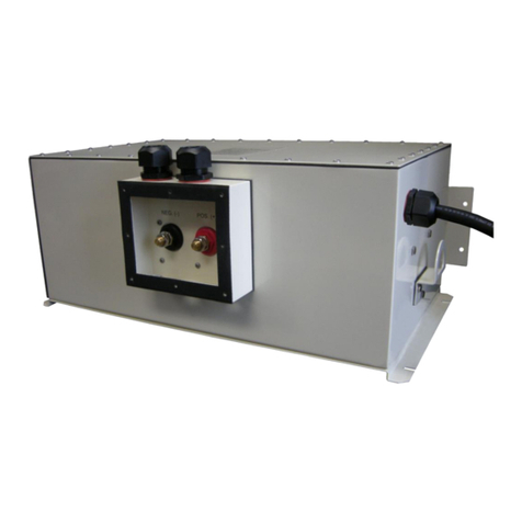
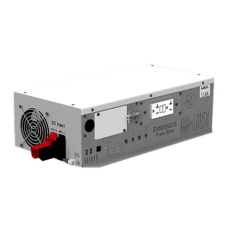
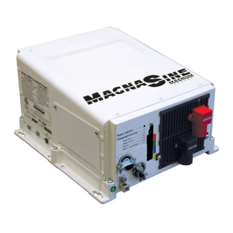
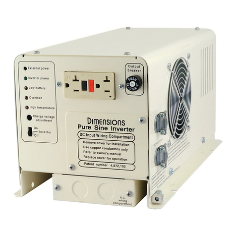
Sensata Dimensions 24NP36 User manual

DC to AC Power Inverter/Charger
24 VDC to 120 VAC
Pure Sine Wave Output
Owner’s Manual
Models:
24NP36

TABLE OF CONTENTS
Introduction....................................................................................................................................................3
Safety Information..............................................................................................................................................................4
Specications.......................................................................................................................................................................6
Components ........................................................................................................................................................................7
Design Features...................................................................................................................................................................8
Installation ......................................................................................................................................................9
Mount the Inverter .............................................................................................................................................................9
Wiring Diagram.................................................................................................................................................................10
DC Wire Gauge & Fusing...............................................................................................................................................11
AC Input & Output Connections ..................................................................................................................................12
BTS Connection................................................................................................................................................................13
Remote Operation ............................................................................................................................................................15
NP Control Board Pinout ...............................................................................................................................................17
Operation ...................................................................................................................................................... 18
Inverter Power Mode .......................................................................................................................................................18
External Power Mode.......................................................................................................................................................18
Operation Using 7-Segment Display .............................................................................................................................22
Operation Using Remote On/Off Switch ...................................................................................................................26
GFCI Operation ...............................................................................................................................................................27
Optional LCD Remote ....................................................................................................................................................28
Congurations .............................................................................................................................................. 29
NVM Setup Utility............................................................................................................................................................29
Congurations...................................................................................................................................................................30
Ignition Switch Control with the 7-Seg Display Panel................................................................................................32
Branch Circuit Rating (BCR) Max Limit with the 7-Seg Display Panel ...................................................................33
Battery Type and Prole with the 7-Seg Display Panel...............................................................................................33
Troubleshooting ........................................................................................................................................... 34
7-Seg Display Panel Messages.........................................................................................................................................34
LED Status Chart .............................................................................................................................................................38
Troubleshooting Guide....................................................................................................................................................40
Appendix....................................................................................................................................................... 41
Accessories & Replacement Parts ..................................................................................................................................41
System Default Settings ...................................................................................................................................................42
Inverter Charger Model Options....................................................................................................................................42
CAN....................................................................................................................................................................................43
Limited Warranty Terms & Conditions ....................................................................................................... 45

24NP Manual Page 3
Introduction
INTRODUCTION
Thank you for purchasing a Dimensions™ inverter/charger from Sensata Technologies®! We think that you will
nd this product to be extremely reliable and easy to use.
Please read this manual completely before installing or operating the unit.
All information is subject to change without warning. Contact Sensata for the latest updates.
Contact Us
Sensata Technologies can be reached by phone or email if you need assistance with this product.
Phone: 1-800-553-6418 or 1-651-653-7000
Fax: 1-888-439-3565 or 1-651-653-7600
E-mail: inver[email protected]
Website: http://magnum-dimensions.com/

Page 4 24NP Manual
Important Safety Information
Read this manual before installation. This manual contains important instructions pertaining to safety, installation,
and operation.
Save this manual and keep it in a safe place.
Sensata Technologies is an ISO 9001:2015 Registered Company.
Sensata uses the following special notices to help prevent injury and/or damage to equipment:
Safety Symbols
DANGER indicates an imminently hazardous situation which, if not avoided, will result in death or serious
injury.
WARNING indicates a potentially hazardous situation which, if not avoided, could result in death or serious
injury.
CAUTION indicates a potentially hazardous situation which, if not avoided, may result in minor or moderate
injury.
CAUTION is used without the safety alert symbol indicates a potentially hazardous situation which, if not avoided,
may result in property damage.
NOTE is used to notify of installation, operation, or maintenance information that is important but not hazard
related.
Safety Listing
Power Inverter, E100666

24NP Manual Page 5
Introduction
Inverter Safety Instructions
WARNING: Customer must match battery type with charger battery type.
WARNING: Power inverters produce hazardous voltages. To avoid risk of harm or re, the unit must be
properly installed.
WARNING: There are no user serviceable parts inside. Do not remove the cover.
WARNING: Power inverters should not be mounted in a location that may be exposed to rain, spray, salt, or
corrosive chemicals.
WARNING: Power inverters should not be installed in a zero-clearance enclosure.
WARNING: Damage to the power inverter will occur if correct polarity is not observed when installing the
inverter’s DC input cables.
WARNING: Damage to the power inverter will occur if an external AC power source is applied to the inverter’s
AC hardwire output.
WARNING: Power inverters contain a circuit breaker and capacitor that may produce a spark upon connection
or during normal operation. Do not mount in a conned battery or gas compartment where toxic fuel vapor is
present.
WARNING: Be sure that the power inverter is turned off and AC power is disconnected when batteries are
being connected, disconnected, serviced, and replaced or personal injury and/or damage to the inverter could
result.
WARNING: Working near lead-acid batteries is dangerous. There is a risk of acid exposure.
Battery Safety Instructions
WARNING: Batteries may vent explosive gases during operation.
WARNING: There is risk of high current discharge from shorting a battery that can cause re and explosion.
Use insulated tools during installation.
WARNING: Remove all rings, watches, jewelry, or other conductive items before working near the batteries.
WARNING: Inspect the batteries at least once a year for cracks, leaks, or swelling. Follow the scheduled
maintenance procedures from the battery manufacturer.
WARNING: Dispose of the batteries according to local regulations. Do not incinerate batteries; there is risk of
explosion.
WARNING: A fuse must be installed between the battery and the inverter to protect against shorted cables.
WARNING: If multiple LFP batteries are connected in parallel, the maximum charger current shall not exceed
the maximum rated charge current of a single battery. This is to prevent overcharging into one battery if
any other battery disconnects during charging. Failure to limit the charge current may result in the battery
disconnecting due to overcurrent and/or may damage the battery.
WARNING: Only use LFP batteries that utilize a BMS that shuts down the battery due to over-current, high
temperature, and cold temperature.
WARNING: The converter/inverter is intended to recharge batteries. The battery that is connected to this
product is only suitable if it complies with the given battery standard for that battery type and is provided with
a battery management system that will monitor and control the electrical and thermal health of the battery
during charging. When installing this converter/inverter, the battery is to be veried as in compliance with the
applicable battery standard.

Page 6 24NP Manual
Specications
WARNING: The inverter is intended to recharge batteries. The battery that is connected to this product is
only suitable if it complies with the given battery standard for that battery type and is provided with a battery
management system that will monitor and control the electrical and thermal health of the battery during
charging. When installing this inverter, the battery is to be veried as in compliance with the applicable battery
standard.
All ratings assume 25.2 VDC nominal voltage, 25°C ambient temperature, and that the inverter is mounted in free
air. Specications are subject to change without notice.
Inverter 24NP36
Enclosure Type Large
Output Power (Watts Cont.) 3600
Output Current (Amps AC Cont.) 30
Input Current (Amps DC Cont.) Up to 167
Peak Power (Watts) 8000
Peak Output (Amps AC) 100
Motor Starting Rating (HP) 2
Weight (lbs.) 68
Dimensions in. (L x W x H) 13.8 x 17.1 x 8
Output Voltage (VAC) 120 +/- 3%
Output Frequency 60 +/- .05%
Output Waveform Pure Sine < 5% THD
Input Voltage (VDC) 21–34
Nominal Input Voltage (VDC) 25.2
Operating Temperature -20°C to 65°C (0°F to 149°F)
Peak Efciency Up to 88%
DC Input Capacitance Up to 160,000µF
Battery Charger
Minimum Req’d Battery A-Hr* 50
Max A-Hr** 500
AC Input Voltage Range (VAC) 95 –135
Nominal Input Voltage (VAC) 120
Input Current (AAC) Up to 25
Output (ADC) Up to 90
Bypass (AAC) 30
Table 1 Specications
* For optimal charging, the inverter amp hour setting should match the amp hour rating of the connected battery.
** Each inverter amp-hr setting can be adjusted with the optional LCD or with RV-C CAN.

24NP Manual Page 7
Introduction
Components
Figure 1 Components
A. DC Input
B. Bonding Lug
C. AC Input & Output (Hardwired)
D. AUX Connector
E. Remote Switch Wiring Tab
F. Status LED
G. 7-Segment Display
H. GFCI
I. AC Wiring Plate
J. 20 A GFCI Output Breaker
K. 30 A Output Breaker
L. BTS Connector Port
M. CAN Port
N. AUX Ports and Connectors

Page 8 24NP Manual
Design Features
• DC Input: Connects to the 24 VDC battery bank.
• Bonding lug: Connects to the system ground.
• AC Input & Output (Hardwired): Terminal blocks are provided behind front access cover for hardwiring AC
Input and Output. A second set of openings to access the AC terminals can be found on the underside of the
inverter/charger when using the large chassis.
• AUX Connector: Currently not used in standard conguration. Mating connector sold separately.
• Remote Switch Wiring Tab: Terminal is used to wire a customer supplied snap style “On/Off ” switch.
NOTE: The 7-Seg display can also be used as a remote. Order remote LCD panel kit# 625000. Alternatively, the
“R” sufx version of the inverter can also be provided with a simple “On/Off ” switch in place of either remotes.
See the “L” option in the Appendix.
• Status LED: This LED will show the operation mode and troubleshooting information. See the table in the
troubleshooting section at the rear of the manual for further mode descriptions.
• 7-Segment Display: Provides limited local control and status of the inverter/charger. The 7-Seg display or an
LCD remote may be purchased separately as a remote. See the “R” option in the Appendix.
• GFCI: Outlet protection; 20 A self-testing receptacle.
• GFCI Output Breaker: Trips to protect the GFCI from shorted AC loads or overload situations.
• Output Breaker: Trips to protect the internal circuitry from shorted AC loads or overload situations. Rated for
30 A.
• BTS: Allows for proper temperature charging across the operating range of the inverter.
• CAN Port: DB9 port used for CAN control of inverter/charger.
• AUX Ports and Connectors: Currently provides no function. May be lled with blank plugs.
• Thermally Controlled Cooling Fan
• Low Battery Protection: Automatically shuts down the inverter at 21.0 VDC with inrush delay.
• High Surge Rating for Large Motor Loads
• Rugged Design for RV/Mobile Environments
• Battery Conguration: Standard models are congured for use with AGM batteries (for charging). Options
for battery type include wet, AGM, gel, and LFP (lithium iron phosphate or LiFePO4). Additionally, there
are four battery prole options for LFP. The battery type may be changed using the optional LCD remote or
through the RV-C CAN tool.
Contact the factory for updated information or for other voltage, current ratings, and battery congurations that
may be available.

Page 9
Installation
24NP Manual
INSTALLATION
Mount the Inverter
NOTE: The inverter mounting location should provide adequate ventilation and clearance to maintain room
temperature during operation. At least ½” of clearance is required on all sides except the bottom. This includes ½”
beyond the mounting anges and DC terminal covers.
Installation Tools
The following tools may be required for inverter installation:
• Wire Termination Crimper
• Cable-Ties
• Drill
• 9/16” Socket or Open Ended Wrench
• Phillips Screwdriver
• Tape Measure
• Wire Cutters
• Wire Strippers
• 3/16’’ Slotted Screwdriver
1. Locate a suitable, secure, vertical or horizontal mounting surface as close to the batteries as possible without
being in the same airtight compartment.
2. Mount the inverter using four ¼-20 steel bolts, at and lock washers, and nuts. The length of the bolts should
be equal to the mounting material thickness plus ¾”.
Figure 2 Large Models Mounting Pattern (Units in Inches)

Page 10 24NP Manual
Typical Wiring Diagram
Figure 3 Typical Wiring Diagram
1. Remove the fuse from the fuse holder.
2. Connect the inverter’s bonding lug to ground of the vehicle chassis.
3. Connect the ring terminated end of the black cable set and the temperature sensor cable directly to either the
negative (-) lead-acid battery post or to the positive (+) LFP battery post.
4. Connect the fuse holder to the positive (+) side of the battery bank.
5. Connect the ring terminated end of the red cable from the inverter to the fuse holder.
6. Inverter DC connectors should be torqued to 160–165 inch-pounds.
7. Install the fuse in the fuse holder. A typical one-time spark will occur when this nal connection is made. Install
the fuse cover.
15 ft. Max
Black Neg (-)
15 ft. Max Red Pos (+) To Chassis Ground
Fuse 18 in. Max Red Pos (+)
Lead-Acid to Battery
Bank Neg (-)
LFP to Battery
Bank Pos (+)
24 VDC Battery

Page 11
Installation
24NP Manual
DC Wire Gauge & Fusing
An “Inverter Cable Kit” (positive cable, negative cable, and proper fuse) is needed to connect the inverter to a
battery bank. An 8 AWG single-strand cable is also recommended to connect the inverter’s bonding lug to ground.
The inverter cable length and the size of the inverter will determine the cable gauge and the fuse size to use. The
maximum recommended length for the inverter cable is 15 feet. The cable must be fused within 18 inches from the
positive (+) terminal of the battery.
Cross reference the inverter model and the estimated cable length in the table below to determine the proper cable
gauge and fuse size. An inverter cable kit designed to SAE guidelines can be purchased directly from our factory –
call for options.
Min. Cable and Max. Fusing Guide for 3% Voltage Drop — 100% Duty Rating
Inverter
Model
Full Load
Amps DC
Inverter to Battery Estimated Cable Length in Feet
1 to 5 feet 6 to 10 feet 11 to 15 feet 16 to 20 feet
24NP36 167 2/0 AWG,
400 A Fuse
3/0 AWG,
500 A Fuse
3/0 AWG,
500 A Fuse
3/0 AWG,
500 A Fuse
Min. Cable and Max. Fusing Guide for 3% Voltage Drop — 50% Duty Rating
Inverter
Model
Full Load
Amps DC
Inverter to Battery Estimated Cable Length in Feet
1 to 5 feet 6 to 10 feet 11 to 15 feet 16 to 20 feet
24NP36 167 1 AWG,
300 A Fuse
1 AWG,
300 A Fuse
1/0 AWG,
350 A Fuse
2/0 AWG,
400 A Fuse
Table 2 DC Fusing Guide
NOTE: 100% duty rating assumes the inverter is operating at its full rated output power continuously for at least
thirty minutes. The 50% duty rating assumes that the inverter is operating at its full rated output power for up to
15 minutes and then operating with a load less than 25% of its full rating for at least 15 minutes before returning
to full power and repeating. Alternatively, it can also operate at 50% of its rated output power continuously. Table
values assume operation in an ambient temperature of 25°C (77°F). For higher ambient temperatures, additional
derating may be required (i.e. may need to use a larger cable size).
NOTE: The DC input terminals will only accept one cable with the provided cover installed. Cover not required for
use.
Make an “Inverter Cable Kit”
1. Use stranded copper cables in all cases.
2. Use SGX cross-linked polyurethane insulation type that complies with the high temperature insulation
requirements (125°C) of SAE J-1127 and vehicle manufacturer requirements.

Page 12 24NP Manual
AC Input & Output Connections
WARNING: Do not connect another source of AC power directly to the output of the inverter. This will result
in damage not covered under warranty.
WARNING: Do not reverse the input and output AC connections. This will result in damage not covered under
warranty.
The inverter’s 120 VAC output power is provided at the GFCI receptacle and the hardwire terminal blocks behind
the access panel. Wire the AC input to the hardwire terminal blocks behind the access panel for charging and shore
power.
1. Remove the black hole covers as needed for hardwire AC wiring. Use a Romex type clamp to protect the wires
from the metal edge of the hole.
2. Apply 14.0 in-lbs torque to the terminal block screws on DIN rail style and 14.6 in-lbs on the white modular
style.
NOTE: Systems rated at 2400 watts and above, the AC input should be protected by a 30 A branch rated input
breaker external to the inverter/charger
NOTE: Connecting the AC inverter input to a GFCI protected outlet may cause some interference with the
inverter’s GFCI.
NOTE: The AC output should be protected by a branch rated breaker external to the inverter if required to comply
with the NEC, NFPA 70, or the Canadian Electrical Code, C22.1.
Figure 4 AC Wiring Terminals

Page 13
Installation
24NP Manual
BTS Connection
Charger operation with a battery temperature sensor, or BTS, cable is required. The BTS measures the battery
temperature and automatically adjusts the charger output for the fastest and safest charge.
Lead-Acid
When batteries are cold, their chemical reaction is slowed, and the battery will not charge as easily in this condition.
A charge voltage optimized for room temperature will not charge the battery at low temperatures. The temperature
sensor cable allows the charger to increase the charge voltage for optimum charging at low temperatures.
When batteries are hot, their chemical reaction is accelerated, and the batteries absorb energy too readily. A charge
voltage optimized for room temperature will tend to overcharge the batteries and cause gassing. The BTS will cause
the charger to decrease the charge voltage to a safe level.
The charger will switch to a “warm battery” mode in which the charger will only provide a oat voltage when the
batteries are between 50°C/122°F and 60°C/140°F. If the battery temperature continues to rise over 60°C/140°F
the charger will shut off. The charger will resume charging in the “warm battery” mode when the battery cools to
55°C/131°F. The charger will resume normal charging when the battery cools to 45°C/113°F.
LFP
Lithium Iron Phosphate (LFP) batteries should not be charged at temperatures less than 0°C/32°F as this may
permanently reduce the battery capacity. The Dimensions inverter/charger can support different proles or modes
for cold charging. The charger can be set to shut down once it reaches the cold shutdown threshold or it can be set
to ignore (not use) the cold shutdown threshold. If set to cold shutdown: After the battery temp sensor warms to
the charge ok temp there is a delay before charging starts. This delay allows the cells located inside the battery time
to warm as there is a thermal lag from the internal cells to the battery post where the battery temp sensor is located.
NOTE: If a user has a battery with a heater, the user should choose proles with cold shutdown disabled or “not-
used.” Ignoring the shutdown will allow the charger to supply voltage to the battery heater (and any other connected
DC load). The current will still be limited to 0.1C so most DC loads should still not be used.

Page 14 24NP Manual
BTS Connection Continued
Install the BTS
1. Connect the lug end of the battery temperature sensor to the battery.
NOTE: Lead-acid battery type will connect the BTS to the negative post of the battery. LFP battery types will
connect the BTS to the positive post of the battery.
2. Connect the connector to the appropriate port located at the rear of the inverter labeled “Temp Sense.” The
BTS is part# ME- BTS-XX (XX=length in feet - 6, 8, 15, 25, 40). The 40 ft version comes standard with the
inverter/charger (unless a non-charger version is ordered).
NOTE: If the BTS is not connected, the battery charger will not function.
Figure 5 Battery Temperature Sensor

Page 15
Installation
24NP Manual
Remote Operation
Install 7-Segment Display Panel
The 7-segment display panel can be removed from the inverter and installed in a different location in the vehicle for
remote control and monitoring.
1. Unscrew the two screws that hold the panel in using a 3/32” Allen wrench.
2. Disconnect the RJ45 connector from the back of the remote panel.
3. Install the RJ45 connector to the backside of the replacement RJ45 cover plate.
WARNING: Mount the RJ45 cover plate on the inverter with the two screws provided in the remote extension
kit (8-32x3/8”). DO NOT USE the screws that held the display to mount the RJ45 cover plate. Using any other
screw type or length than that provided in the kit may damage the inverter and/or harm the installer. Tighten
the screws to 16–17 inch-pounds.
4. Connect the extension cable to the RJ45 jack.
5. Route the cable through the vehicle to the desired location.
NOTE: Avoid routing the RJ45 connector around high current power cables.
6. Install the remote display panel at the desired new interior location using installer supplied #8 screws and
connect the extension cable to it.
To mount remotely, the 7-Seg Display panel will require the mounting hole and screw positions shown below:
Figure 6 Seven-Segment Display Hole Pattern

Page 16 24NP Manual
Remote Operation Continued
Remote Inverter “On/Off ” Switch
An optional customer-supplied remote switch can also be used to control the inverter.
Install Remote Inverter “On/Off ” Switch
1. Using an insulated female faston and 18 AWG wire, wire between the “Remote On/Off ” connection on the
right side of the inverter and the remote switch.
2. Wire from the remaining connection on the remote switch to the battery.
3. Install a 5 A in-line fuse installed in series within 18 inches from the positive (+) terminal of the battery.
Figure 7 Remote On/Off Wiring
24 VDC Battery
Remote
On/Off Switch
Fuse

Page 17
Installation
24NP Manual
NP Control Board Pinout
An additional switch may be installed as an optional way to enable the inverter. Enable remote operation by
installing a switch between between the pin 4 and 6. The installed switch must be rated for 80 V minimum.
Figure 8 Pinout
Board Pinout
ACC / Remote
(RJ12)
PIN 1 & 3 Digital Ground
PIN 2 CAN-H
PIN 4 Remote + (Output, DC Power Fused at 2 Amps)
PIN 5 CAN-L
PIN 6 Inverter Request (Input)
Battery
Temperature
Sensor (RJ12)
PIN 1 N/C
PIN 2 & 5 Sensor Signal Input
PIN 3 Sensor Ground
PIN 4 & 6 N/C
CAN Bus (DB9)
PIN 1, 4, 5, 6, 8, & 9 N/C
PIN 2 CAN-L
PIN 3 CAN REF, GND (N/C)
PIN 7 CAN-H
SYNC/STACK
(RJ45) - Not Yet
Supported
PIN 1 & 2 Digital Communication
PIN 3 & 4 N/C (Not Connected)
PIN 5 & 6 Digital Communication
PIN 7 N/C
PIN 8 Inverter Request (Output)
Table 3 Pinout
GND
CAN H
GND
CAN L
Vbatt
Inverter
Request
ACC Jack
1 2 3 4 5 6

Page 18 24NP Manual
OPERATION
Inverter Power Mode
Control the inverter with the display panel “On/Off ” key or a voltage between 8 and 32 volts applied to the
“Remote On/Off ” input tab.
The 7-segment display panel “On/STBY” LED will be green, and the status LED will blink amber while the
inverter is on. The AC power produced by the inverter comes from the energy stored in the battery bank. A
transformer, a Metal Oxide Silicon Field Effect Transistors (MOSFET), a lter capacitor, and microprocessor
control are used to generate clean AC power with THD <5%.
The inverter will operate at DC input voltages ranging from 21 to 34 volts. If the DC input measures between
33 and 34 volts for greater than ve minutes, the inverter will shut down. Above 34 volts, the system will stop
operating due to input voltage being out of range. The inverter can tolerate up to 34 VDC input. When the input
voltage drops to 21.0 volts, the inverter will stop operating due to a low battery condition. When the lead-acid
battery bank voltage drops to 21 volts, the battery is considered to be fully discharged.
NOTE: Inverters have a large capacitance on the DC input terminals. If the capacitors are discharged when
LFP batteries are connected, a large inrush current may occur. The inrush current may cause the BMS within the
LFP battery to immediately disconnect. This issue will occur if the amount of connected battery amp-hrs is not
sufcient to support the inverter size.
External Power Mode
The 7-segment display panel will show charger mode and output and the status LED will blink green indicating
that there is a valid external AC power line applied to the inverter AC input. There may be a 30 second delay before
charge or bypass is enabled while the AC input power is qualied.
Bypass Relay
The loads attached to the inverter output will operate directly from the external AC power line independently of
the inverter on/off status. If the inverter is left on (standby mode), the built-in bypass relay will automatically cycle
back and forth between “inverter power” and “external power” mode depending on the availability of the external
AC power line.
Battery Charger
WARNING: Customer must match battery type with charger battery type.
The battery charger will engage automatically and independently of the inverter on/off status.
NOTE: When in charge mode, the charger may not be able to charge at its full capacity if AC power is being used
in bypass mode.
NOTE: The charger is capable of charging AGM, gel, wet lead-acid, or LFP batteries. The battery type may also
be set via the 7-Seg Display, the optional LCD remote display (sold separately), or RV-C CAN. Contact factory for
further details on RV-C CAN. The LCD part number may be found in the Appendix.

Page 19
Operation
24NP Manual
External Power Mode Continued
Battery Charger Continued
Battery Type AGM Gel Wet LFP
Bulk Charge Phase
Bulk
Current Limit SEE SPEC
Phase Terminates 1. When battery voltage reaches the accept voltage
2. When the bulk charge timeout is reached
Phase Timeout
6 Hours
Bulk charge timers will extend when load management
reduces charger current below 50% (25 A)
Accept Charge Phase
Accept
Accept charge voltage
@ 77°F/25°C 28.6 VDC 27.4 VDC 29.2 VDC 28.8 VDC
Accept voltage temp compensated 5mv/cell/°C
Maximum accept charge at low
temps 30.0 VDC @ 4 °C 29.0 VDC @
-6°C
30.0 VDC
@ 10°C N/A
Phase Terminates
1. When charge current is reduced.
2. When the accept timeout is reached.
3. If the charger can’t maintain the accept voltage
Phase Timeout 6 hours (may be congured through CAN or LCD) 0.5 hours
Float Charge Phase
Float
Float voltage @77°F/25°C 26.8 VDC 26.8 VDC 26.4 VDC 27.2 VDC
Float voltage temp comp 5mv/cell/°C
Condition (Equalization) Phase
Condition
Condition voltage @77°F/25°C N/A N/A 15.5 VDC N/A
Condition voltage temp
compensation N/A N/A 30.24 mV/
cell/°C N/A
Condition duration N/A N/A 4 hours N/A
Condition frequency N/A N/A Manual
Control N/A
Table 4 Battery Charger Recipes with BTS

Page 20 24NP Manual
External Power Mode Continued
Battery Charger Continued
Battery Type AGM Gel Wet LFP
Battery Temperature
Battery Temp
Charger Warm Battery: output switches to
compensated oat from bulk/accept/off (hot)
>50°C/ 122°F
<60°C/140°F N/A
Charger High Battery Temp: output to off >60°C/140°F See Prole
Charger resumes in previous mode: bulk/
accept/oat <45°C/112°F Prole value
-5°C
Charger Low Battery Temp Off: output to off N/A See Prole
Enter 0.1C charge rate from Charger Low
Temp Off N/A
Chg Low
Temp Off
value +5°C
Enter 0.1C charge rate from bulk/accept/oat N/A See Prole
Charger 0.1C charge rate recovery to bulk/
accept/oat mode N/A See prole
value +5°C*
Table 4 Continued Battery Charger Recipes with BTS
*Prole value +15°C when charge cycle starts cold plus elapsed minimum time in mode.
Load Management
Incoming AC power is shared between the AC loads and the charger. The AC loads are given priority; this means
that the charger will reduce its output when AC loads are applied. This feature also controls the total amperage draw
of the system so that the utility service circuit breaker is not tripped. The load management feature will return the
charger to full output when the AC loads are removed or reduced.
Figure 9 Load Management
The total amperage draw of the system is controlled by the AC limit setting also known as the BCR. These terms
may be used interchangeably. The default AC limit is set by the factory to 15 A. The BCR may be changed at the
factory or through the NVM Setup Utility, 7 Seg Display, or the optional LCD remote.
NOTE: Dynamic external loads (such as motors or pumps that continuously vary the power required) may cause
variations in the charge rate. The charger may reset if the dynamic load causes the input AC waveform to become
temporarily disqualied.
Table of contents
Other Sensata Inverter manuals

Sensata
Sensata 12/800N User manual

Sensata
Sensata Dimensions 12LPC15 User manual

Sensata
Sensata Magnum-Dimensions MagnaSine MS-G Series User manual

Sensata
Sensata Dimensions 12LP15 User manual

Sensata
Sensata MAGNUM ENERGY MM Series User manual

Sensata
Sensata MIL-24XM15N User manual

Sensata
Sensata 24TX60 User manual

Sensata
Sensata Magnum Energy CSW3012-X User manual

Sensata
Sensata ADI-300/3000D User manual

Sensata
Sensata Magnum Energy MS Series User manual