Baxi Solarflo Guide

Commissioning, Maintenance & Servicing Guide
Solarflo - Solar Thermal Domestic Hot Water System
© Baxi Heating UK Ltd 2007.
Please read these instructions before installing or commissioning.
The Solarflo - Solar Thermal Domestic Hot Water System should
only be installed by a competent person.
Please leave these instructions with the user for safe keeping.

Solarflo - Solar Thermal Domestic Hot Water System2
Index
© BAXI Heating UK Ltd 2007. All rights reserved. No part of this publication may be reproduced
or transmitted in any form or by any means, or stored in any retrieval system of any nature
(including in any database), in each case whether electronic, mechanical, recording or otherwise,
without prior written permission of the copyright owner, except for permitted fair dealing under
Copyrights, Designs and Patents Act 1988.
Applications for the copyright owner’s permission to reproduce or make other use of any part of
this publication should be made, giving any details of the proposed use to the following address:
The Company Secretary, BAXI Heating UK Ltd,The Wyvern Business Park, Stanier Way, Derby DE21 6BF.
Full acknowledgement of author and source must be given.
WARNING: Any person who does any unauthorised act in relation to a copyright work may be
liable to criminal prosecution and civil claims for damages.
2 Index
3 Commissioning of system
General information
Flushing and filling the system
5 Commissioning of hydraulic station
Checking/setting pressure
Checking/adjusting flow rate
Installation of thermal insulation
7 Commissioning of solar controller
Overview of display
Button function
Operating menu
Menu structure
"Info"
"Programming"
"Manual operation"
"Basic adjustment"
Controller functions
21 Commissioning record
22 Servicing and maintenance record
24 Maintenance
Check heat transfer fluid
Maintenance of the collector
25 Fault finding
Failures with error message
Resistance table
Flow charts
28 Spares
30 Warranty

Solarflo - Solar Thermal Domestic Hot Water System 3
1.0 Commissioning of system
1.1 Commissioning - General
The Baxi Solarflo system uses a sealed system indirect
solar primary circuit which must be filled with the solar
heat transfer fluid provided. This is pre-diluted to the
appropriate strength (40% glycol/60%water) and should
not be diluted further. Use only the fluid supplied.
Additional canisters of solar fluid are available in 10 litre
(5119550) and 20 litre (5119549) bottles.
DO NOT mix the fluid with other types.
The system should be filled when there is no direct
radiation from the sun. If direct radiation occurs the
collector panels should be shaded by covering them
during filling and flushing.
Although the solar heat transfer fluid is non corrosive
and biodegradable appropriate precautions should be
taken when handling.
- Wear protective gloves and goggles.
- Wash with soap and water if the fluid comes into
contact with skin.
- If fluid gets into eyes, immediately rinse with large
quantities of clear running water.
- A full safety and specification sheet can be obtained
by request.
The solar heat transfer fluid must be pumped into the
system.The pump can be electric or manual but must be
capable of producing a pressure of at least 2 bar.
The system should be thoroughly flushed to remove any
contaminants in the solar primary circuit prior to filling
with the heat transfer fluid

Solarflo - Solar Thermal Domestic Hot Water System4
1.0 Commissioning of system
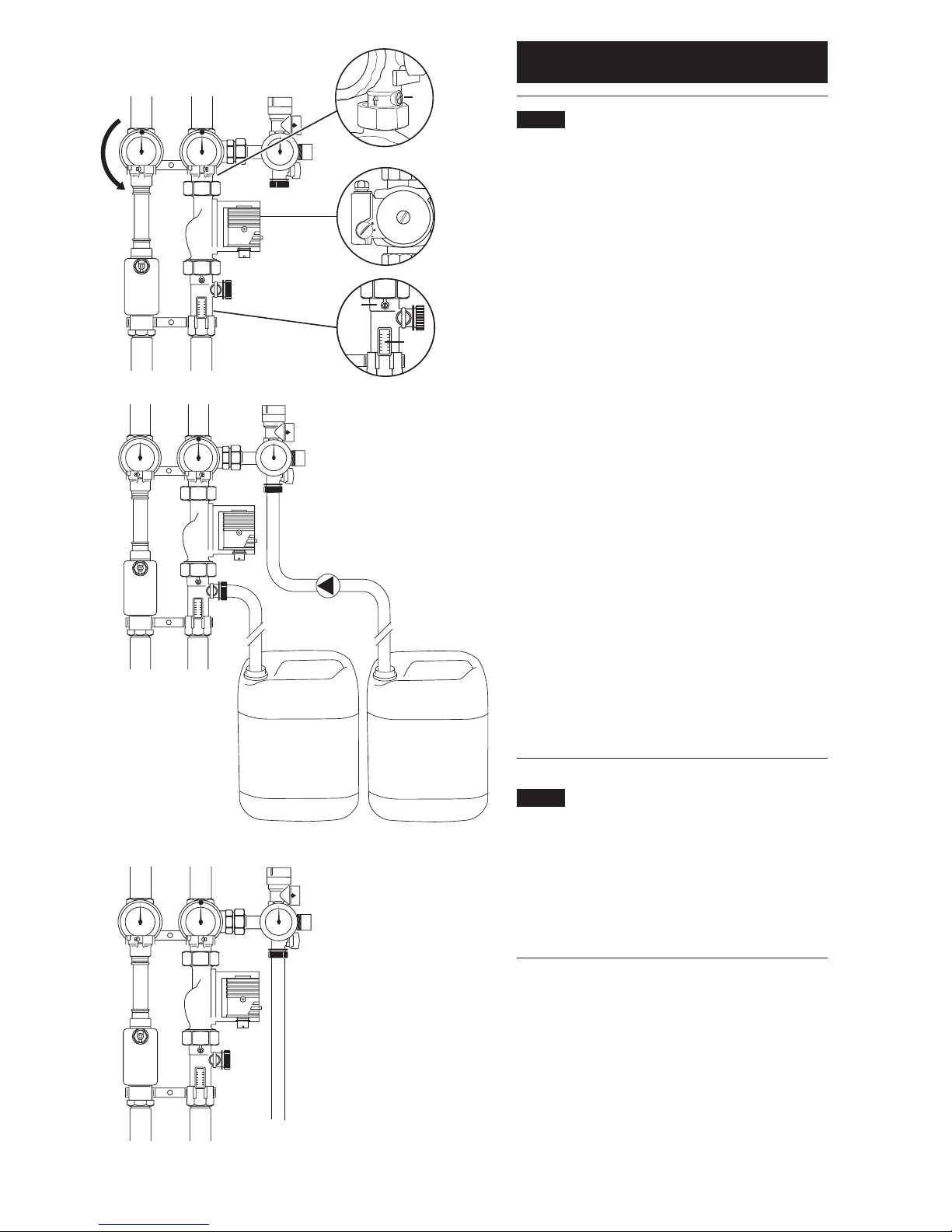
1.2 Flushing the pipework
Before the system is commissioned the pipework must
be flushed to remove any contaminants. It is recommended
that this is done using the solar heat transfer fluid as it
will be impossible to fully drain all parts of the system.
Connect the flushing pipes to the fill & drain valve on
the safety group (Fig. 1 Item 1) and to the fill & drain
valve on the flow meter (Fig. 1 Item 2).
Open the fill & drain valves.
Turn the slot of the adjusting screw (Fig. 1 Item 3) in the
return so the slot is vertical to open the non-return
valve.
Turn the left hand isolating valve with integral
thermometer in the flow (Fig. 1 Item 4) in the direction
indicated by the arrow (to a 45° position) to open the
non-return valve.
Ensure that the right hand isolating valve with integral
thermometer in the return (Fig. 1 Item 5) is open
indicated by the dot on the thermometer bezel being
at the top.
Turn the slot of the adjusting screw of the flow meter
(Fig. 1 Item 6) in the return vertically to open the flow
limiter (Fig. 1 Item 7).
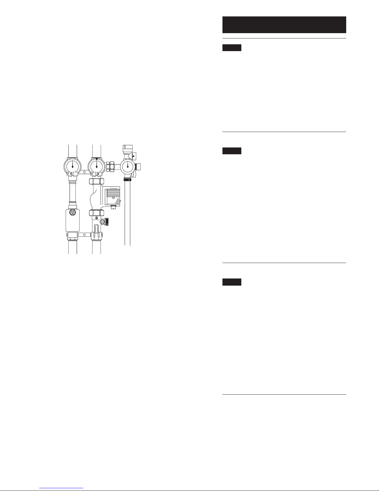
Flush the solar primary pump by pumping the fluid into
the system via the fill and drain valve on the safety group.
Close right hand isolating valve (dot on thermometer
bezel at 9 o’clock position). Flush solar primary pipework
and panels via the fill and drain valve on the safety group.
If reusing flushed fluid ensure this is filtered before
re-introducing into the system
(see Fig. 2).
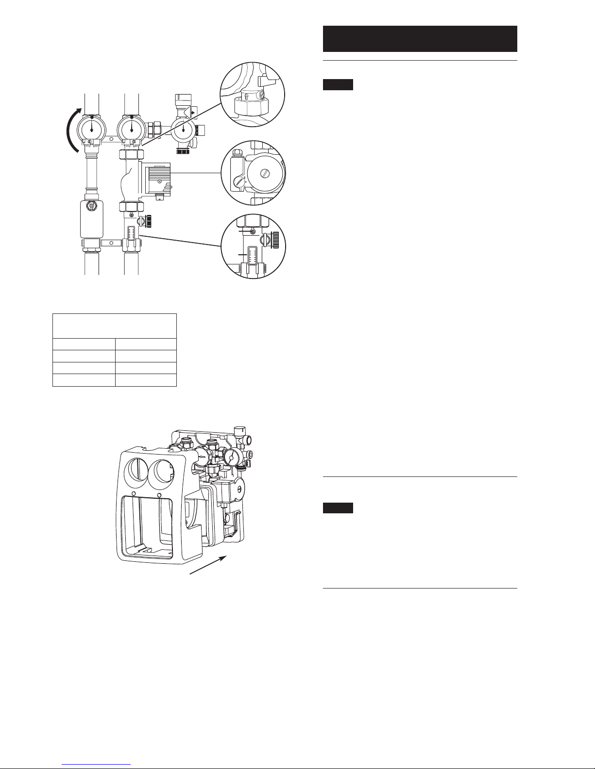
1.3 Filling the pipework
Close the fill and drain valve (Fig. 3 Item 2) on the flow
meter. Open the righthand isolating valve (Fig. 3. Item 1)
with integral thermometer by turning so that the dot on
the bezel is at the top. Fill the solar primary system by
pumping in fluid until the system pressure reads 1.5 to
2.0 bar. Close the fill and drain valve (Fig. 3. Item 3) on
the safety group.
45
3
6
7
Fig. 1
Fig. 2
Fig. 3
Solar fluid Solar fluid
Filling pump
Filter
1
2
1
3
2

Solarflo - Solar Thermal Domestic Hot Water System 5
2.0 Commissioning of hydraulic station
2.1 Check pressure in the solar primary
pipework
After flushing and filling the solar primary system with
heat transfer fluid the pressure must be checked.
Pressure test the system (6 bar). Observe the maximum
pressure ratings of all components concerned.
Check the solar heating system for leaks.
Close the fill and drain valve on the safety group.
2.2 Ensure the solar primary system is free
from air
Switch on the power supply to the solar differential
temperature controller.
Manually switch the circulation pump ON and OFF
via the solar differential temperature controller
(see section 3.1.7) to pump fluid around the solar
primary system.
Turn the pump off and open the airbleed screw on the
air separator (Fig. 4 Item 1). Bleed any air from the air
separator. If the system pressure drops top up by opening
the fill and drain valve (Fig. 4 Item 2) on the safety group
and pumping in more solar fluid to restore the pressure.
This must be repeated until the pressure remains stable.
2.3 Setting the system pressure
During commissioning, the system pressure should be
0.7 bar above the static pressure (1 metre height
differential equals 0.1 bar). However, it must be at least
1.5 bar and no higher than 2.2 bar.
Determine the system pressure when the system is
cold (20°C).This should be recorded on the
Commissioning Record Sheet (page 21).
If the pressure is too low you should pump additional
heat transfer fluid into the system; the fill & drain valve
on the safety group (Fig. 4 Item 2) needs to be opened
for this purpose.When system pressure is correctly set,
ensure the fill and drain valve is closed and remove filling
hose from safety group.
Fig. 4
1
2

Solarflo - Solar Thermal Domestic Hot Water System6
2.0 Commissioning of hydraulic station
2.4 Checking and adjusting the flow rate
Adjust the flow rate when the system is cold (20°C)
(see Fig. 5).
The flow rate should be adjusted to give the optimum
flow rate depending on the number and type of
collector panels connected.
Turn the slot of the adjusting screw (Fig. 5 Item 1) below
the return temperature gauge horizontally to close the
non-return valve.
Turn the l.h. isolating valve with integral thermometer in
the flow (Fig. 5 Item 2) as far as it will go in the direction
indicated by the arrow to close the non-return valve (dot
on bezel on top).
Turn the slot of the adjusting screw (Fig. 5 Item 3) in the
return vertically to open the flow limiter on the flow
meter (Fig. 5 Item 4).
Manually operate the solar pump (see section 3.1.7).
Set the solar pump switch (Fig. 5 Item 5) so that the
required flow rate is achieved or exceeded with the
lowest possible setting.The flow limiter adjusting screw
(Fig. 5 Item 3) can be used to fine-tune the flow rate.
Depending on the number and type of collectors installed,
set the required flow rate from table (See Table 1).
The float in the flow meter will indicate the circulation
flow rate through the flow meter sight glass.
Adjust screw of the flow limiter (Fig. 5 Item 3) with a
screwdriver, until the upper edge of the float in the sight
glass indicates the required flow rate.
Set manual pump operation to off.
2.5 Installation of the thermal insulation
Refit the controller mounting moulding (Fig. 6 Item 1)
onto the rear moulding.
Push the front thermal insulation (Fig. 6 Item 2) against
the rear thermal insulation section (Fig. 6 Item 3) until it
clips into place.
Flow rate
(when system is cold)
Collectors l/min
1 approx. 2
2 approx. 4
3 approx. 6
Fig. 5
Fig. 6
2
5
3
4
1
2
3
1
Table 1

Solarflo - Solar Thermal Domestic Hot Water System 7
Graphic symbol Description Indication in operation
Indicator values
dT Temperature difference
min Min value Appears when minimum values are indicated
max Max value Appears when maximum values are indicated
min Timeframe 1 start Appears when the differential controller is active
0:00 (timeframe 1-3) or tube collector is active (timeframe 4)
1
Max Timeframe 1 stop Appears when the differential controller is active
23:59 (timeframe 1-3) or tube collector is active (timeframe 4)
1
5 x 7 segment display. Display of all values, display flashes when
Presentation of figures 00000 to 99999 a value is changed
ºC Temperature in Celsius
KTemperature difference in Kelvin
hOperating hours
kWh Productivity indication in kWh
3.0 Commissioning of solar controller
3.1 Overview of display and operating elements
Number Description
1 Display with graphic symbols
2 Control button scroll upwards / +
3 Control button exit / break-off
4 Control button scroll downwards / –
5 Control button choice / confirmation
3.1.1 Explanation of graphic symbols
When symbol flashes it is possible for it to be
selected. If that symbol is chosen by pressing the
button, the symbol remains static (not flashing).
Graphic symbol Description Indication in operation
Main Menu
Menu "Info"
Menu "Programming"
Menu "Manual operation"
Menu "Basic adjustment"
1
2
4
35
Fig. 7
(see Fig. 7).

Solarflo - Solar Thermal Domestic Hot Water System8
3.0 Commissioning of solar controller
Graphic symbol Description Indication in operation
Measuring points assignment
Temperature measuring point collector array 1
Temperature measuring point collector array 2
Temperature measuring point storage tank 1 lower
(storage tank 1 charging)
Temperature measuring point storage tank lower
(storage tank 2 charging)
Temperature measuring point collector - return
Temperature measuring point storage tank upper
(thermostat function)
Antifreezing sensor or universal temperatures
measuring point (T6) (no sensor monitoring)
2nd temperature differential controller
Operating hours, energy productivity measurement
Status indication
Solar circulation pump Symbol revolves when solar circulation pump is on
Switch output 1 is active Appears when switch output 1 is active (on)
Switch output 2 is active Appears when switch output 2 is active (on)
Switch output 3 is active Appears when switch output 3 is active (on)
Reference to system fault Display flashes when a fault occurs in the system
Safety query for value changes which are to be stored Input value can be either
rejected or accepted
!
ok?

Solarflo - Solar Thermal Domestic Hot Water System 9
Button Function Icon after operation step Description
"Exit" Exit menu's "Info"
"Scroll right" Choosing menu "Programming"
"Call" Call up menu "Programming", the first menu
point appears
"Down" Repeated pressing up to menu point
"S1 dTmin" appears
"Choice" Choosing presented character
"Up" Increase of parameter
"Confirm" Confirmation of the character
"Confirm" Storing of the parameter
"Exit" Exit menu "Programming"
"Scroll left" Choosing menu "Info"
"Call" Call up menu "Info"
Max
65°C
ok?
dT min
3K
dT min
3K
dT min
4K
dT min
4K
dT min
4K
60°C
Currently selected menu icon will flash
Chosen menu icon will flash
When chosen, value to be changed will flash
"ok?" icon will flash
When stored, icon will stop flashing
Currently selected menu icon will flash
Chosen menu icon will flash
Example of setting procedure
Button Function Description
"Up" • Step up through menu
"+" • Value change: Increase of the indicated value by 1, holding the button down will
automatically increase values
"Call" • Call up of main menu, step down through menu
"Down" • Value change: Decrease of the indicated value by 1, holding the button down will
automatically decrease values
"Scroll left" • In main menu, scrolls to the left
"Exit" • Exit current menu
• Exit menu point
"Break-off" • Break-off value change without storing
"Scroll right" • In main menu, scrolls to the right
"Choice" • Choosing one menu point
"Confirmation" • Confirmation of value change, stores value change
3.1.2 Button function
Operation and programming of the Solarflo differential
temperature controller is by means of 4 operating buttons.
By means of pressing these buttons you can:
• recall display values
• carry out controller adjustments
The graphic symbols on the display step through the
operating structure and show clearly the current menu
points, display values or parameters.
Operating buttons have the following functions:

Solarflo - Solar Thermal Domestic Hot Water System10
3.0 Commissioning of solar controller
3.1.3 Operating menu
To make the operation of the controller clear, operating
and display functions are divided into 4 main menus.
These are
• Info
• Programming
• Manual operation
• Basic adjustment
Each active menu is shown in the upper line of the
display by its corresponding icon.
Menu Description
Info Main menu for automatic regulation of solar system
• Indication of current measured values
• Indication of system condition
• Indication of error messages
• Indication of operating hours and energy productivity (if installed)
Programming Changes to programmable values (parameters)
Note: Changes can affect system functions!
Manual operation Switching on and off connected pumps / valves by hand. Overrides automatic regulation.
Basic adjustment Information about basic adjustment for system function
Important
Adjustments and changes in this menu must be carried out only by a competent
installer or service engineer.

Solarflo - Solar Thermal Domestic Hot Water System 11
3.1.4 Overview: Construction of menu structure
The overview shows the whole menu structure.
According to basic adjustment and system type some
menu points may not be displayed.
Info Program Manual operation Basic setting
Current collector temperature Maximum temperature Pump1 off / on Collector protection function
/ Collector1 storage cylinder1 off / on
Minimum collector temperature Storage cylinder1 Pump2 / Valve1 Collector protection
/ Collector1 Td max (Td on) off / on temperature
Maximum collector temperature Storage cylinder1 Heating / Cooling / Temperature Re-cooling
/ Collector1 Td min (Td off) differential controller off / on
off / on
Current storage cylinder Maximum temperature of Re-cooling
temperature / storage1 at bottom storage cylinder2 temperature
Minimum storage cylinder Storage cylinder2 Tube collector
temperature / storage1 at bottom Td max (Td on) off / on
Maximum storage cylinder Storage cylinder2 Yield estimation
temperature / storage1 at bottom Td min (Td off) off / on
Current storage cylinder temp / Minimum Glycol type
storage2 at bottom / collector 2 pump rotating speed in %
Minimum storage cylinder temp / Start temperature Glycol percentage
storage2 at bottom / collector 2 Heating / cooling
Maximum storage cylinder temp / Hysteresis temperature Volume flow
storage2 at bottom / collector 2 heating / cooling Td
Current collector Temperature differential Controlling time in
temperature - return line controller: seconds
Maximum temperature of the
heating target Tmax
Current temperature Temperature differential Storage cylinder priority
heating / cooling / controller:
differential controller Minimum temperature of the
heating source heating source Tmin
Current temperature Temperature differential Frost protection
frost protection sensor / controller: off / on
differential controller heating Hysteresis Tdmax
target / universal measuring
point T6
Operating hours pump1 Temperature differential Frost protection sensor
controller: assignment
Hysteresis Tdmin
Yield storage1 Timeframe start 1,2,3 for the Frost protection:
independent controller, 4 for the start temperature
tube collector function
Operating hours pump2 Timeframe stop 1,2,3 for the Independent controller
independent controller, 4 for the assignment: Cooling, heating,
tube collector function temperature differential
controller
Yield storage2 Set time Sensor assignment for the
independent controller
Select basic configuration
3.0 Commissioning of solar controller

Solarflo - Solar Thermal Domestic Hot Water System12
3.0 Commissioning of solar controller
3.1.5 Menu “Info”
In this menu mode all measured values and operating
states are shown.
If the values are marked as “resettable”, they may be
reset in the following way:
Choose the value with buttons and
Reset value by means of the button
Message “OK?” confirm with = no or = yes
Indication Description Reset possible
75ºC Indication of current collector temperature no
min. 12ºC Indication of minimum collector temperature yes
Re-settable to current temperature
max. 105ºC Indication of maximum collector temperature yes
Re-settable to current temperature
52ºC Indication of current temperature storage tank (lower) no
min. 40ºC Indication of minimum temperature storage tank (lower) yes
Re-settable to current temperature
max. 67ºC Indication of maximum temperature storage tank (lower) yes
Re-settable to current temperature
25ºC Indication of universal temperature measuring points (T3) no
55ºC Indication of current temperature storage tank thermostat no
60ºC Indication of current temperature collector return no
60ºC Heating, cooling, temperature differential controller no
heat source. Sensor T1...T6
35ºC Temperature differential controller no
heat target
1234 h Operating hours for charging storage tank Yes
Resettable to 0 h
927 kWh Energy productivity for storage tank Yes
Resettable to 0 kWh

Solarflo - Solar Thermal Domestic Hot Water System 13
3.0 Commissioning of solar controller
3.1.6 Menu “Programming”
All adjustable parameters can be checked in this menu
and, if necessary, changed.The default factory set values
will usually give efficient, problem free operation.
The number of indicated values depends on the
controller type and the adjusted additional functions.
Only the required values are shown at each menu step:
Indication Description Value range Defaults
max Storage 1/2: 15..95ºC 65ºC
65ºC Maximum temperature
dT max Storage 1/2: Hysteresis (Tdon) 3..40 K 7 K
7 K
dT min Storage 1/2: Hysteresis (Tdoff) 2..35 K 3 K
3 K
min Setting the speed control of the pump 30%..100% 100%
100 100% = speed control off
13:21 Clock 0:00...23.59 12:00
min Temperature start for the function 20..90ºC 40ºC
40ºC heating/cooling
dT Hysteresis heating/cooling 1..30K 10K
10K
max Differential controller: Maximum 15..95ºC 65ºC
65ºC temperature of heat target Tmax
min Differential controller: Maximum 0..95ºC 15ºC
15ºC temperature of heat source Tmin
dTmax Temperature differential controller: 3..40K 7K
7 K Hysteresis dTmax
dT min Temperature differential controller: 2..35K 3K
3 K Hysteresis dTmin
min Timeframe 1(2,3): Start 0:00... 00:00
00:00 for the independent controller 23.59
1(2,3)
max Timeframe 1(2,3): Stop 0:00... 23:59
23:59 for the independent controller 23:59
1(2,3)
min Timeframe 1(2,3): Start 0:00... 6:00
6:00 for the tube collector function 23:59
4
max Timeframe 1(2,3): Stop 0:00... 20:00
20:00 for the tube collector function 23:59
4
2

Solarflo - Solar Thermal Domestic Hot Water System14
3.0 Commissioning of solar controller
3.1.7 Menu “Manual operation”
For commissioning, service and test purposes the solar
primary system can be manually operated. For this purpose
the switch outputs may be disconnected or connected.
During manual operation there is no automatic regulation
of the system.To avoid inadmissible operating states this
mode of operation changes into “Indication” after ca.
8 hours and the automatic regulation is activated again.
Indication Description Value range
Switching on / off switch output A1 (solar circulation pump) by hand 0 = off
1 = on
Switching on / off switch output A2 (pump2 / valve1) by hand 0 = off
1 = on
Switching on / off switch output A3 (cooling, thermostat or 2nd temperature 0 = off
difference controller function) by hand 1 = on

Solarflo - Solar Thermal Domestic Hot Water System 15
3.1.8 Menu “Basic adjustment”
Adjustments and changes in this menu must be carried
out only by a competent installer or service engineer.
Incorrect adjustments may adversely affect the
function of controller and solar primary system.
To avoid accidental changes in menu “Basic adjustment”,
it is not editable in normal functioning but has only a
display function.To be able to carry out any changes, this
menu must be chosen within the first minute after
switching on the appliance. The basic adjustment menu is
‘blocked’ automatically one minute after if no buttons are
pressed or one minute after switching on the appliance.
3.0 Commissioning of solar controller
Indication Description Value Factory
range set-up
0 – 0 Collector protection 0 = off 0 = off
1 = on
1 – 120ºC Start temperature for the collector protection 110..150ºC 120ºC
2 – 0 Re-cooling function (only when collector 0 = off 0 = off
protection is on) 1 = on
3 – 40ºC Target temperature for the storage after 30..90ºC 40ºC
collector protection activity
4 – 0 Time controlled circulation with 0 = off 0 = off
tube collectors 1 = on
5 – 0 Yield estimation off/on 0 = off 0 = off
1 = on
6 – 0 Glycol types (see table below) 0...10 0
7 – 50 Glycol percentage 0 ... 100% 50
5% - steps
8 – 1,0 Volume flow: Litre per impulse - flow meter 0,5 ... 25 I/I 1,0
0,5l - steps
9 – 240 Time controlling in s 30...480 240
10 – 1 Storage priority 1...2 1
11 – 0 Frost protection on/off 0 = off 0
1 = on
12 – 6 Sensor assignment - Frost protection 1...6 6
13 – 3 Start temperature for the frost protection function -20ºC ... +7ºC 3
14 – 0 Select cooling thermostat 0 = off 0
or temperature differential controller 1 = cooling
2 = heating
3 = temperature
differential controller
15 – 5 Sensor assignment for the independent controller (source) 1...6 5
16 – 0 System configuration 0...4 0
Glycol types (point 6):
0 Anro 6 Tyfocor L5.5 - supplied
1 IIexan E, Glythermin 7 Dowcal 10
2 Antifrogen L 8 Dowcal 20
3 Antifrogen N 9 Dowcal N
4 IIexan E 10 Tyfocor LS
5 IIexan P
Parameter / value

Solarflo - Solar Thermal Domestic Hot Water System16
3.0 Commissioning of solar controller
3.1.9 Controller functions
The Baxi Solarflo differential temperature controller
contains many functions to regulate and monitor the
solar primary system. Including
- controller functions for heating the solar cylinder
- functions for system protection and system monitoring
- additional functions (other accessories may be required
to achieve these functions).
3.1.10 General controller functions
The controller collects the temperatures of various
measuring points and determines the right time to charge
the storage tank on account of programmed (additional)
functions and controller parameters.
3.1.11 Cylinder heating by solar primary system
Switching action can be adjusted through dTmax (dTon)
and dTmin (dToff), but dTon cannot be set lower than dT
off + 1K .The solar cylinder is heated by operating the
solar pump on output A1 up to the set maximum storage
temperature. Pump operation is allowed as long as the
collector panel temperature exceeds the cylinder
temperature by a set amount.
3.1.12 Systems with two storage cylinders
For systems with more than one storage cylinder (System
Types 1 and 2) the cylinder heating can be optimised
depending on the energy supply. Usually the cylinder with
lower priority will have a lower temperature than that
with the higher priority. Re-directing the energy to the
lower priority cylinder will lower the temperature in the
collector array.To “reinforce” the collector temperature
the heating of the lower priority cylinder will be
interrupted for a short while at fixed intervals. If the
heating criteria for the higher priority cylinder is fulfilled
then the lower priority cylinder will be heated.
The higher priority cylinder can be selected in the
“Basic Settings” menu point no. 10.
“Basic adjustment” “Programming”
--- Maximum temperature
--- dT max (dT on)
Switch-on temperature difference
--- dT min (dT off)
Switch-off temperature difference
Corresponding values in menu

Solarflo - Solar Thermal Domestic Hot Water System 17
“Basic adjustment” “Programming”
14 -- 1 Start temperature max ºC
15 -- 5 Hysteresis Td in K
Timeframe (1…3) Start: min time
Timeframe (1…3) Stop: max time
Corresponding values in menu
“Basic adjustment” “Programming”
14 -- 2 Start temperature max ºC
15 -- 5 Hysteresis Td in K
Timeframe (1…3) Start: min time
Timeframe (1…3) Stop: max time
Corresponding values in menu
“Basic adjustment” “Programming”
--- Rotational speed min <100%
Corresponding values in menu
3.1.13 Rotational speed regulation
The solar circulation pump on 230V-outputs A1 and
A2 can be operated either in switch-mode (two-point
controller) or in a rotational speed regulated way.
If the rotational speed regulation is activated the pump
power is adjusted by a controller so that switch-on
temperature difference “Storage tank dTmax” is kept
constant as much as possible.At lower deviation of
“Storage tank dTmax” the pump is operated with the
lowest power till the switch-off wave is reached.
3.1.14 Thermostat (heating)
The thermostat is a control circuit that’s independent
from the storage loading.Thus an auxiliary heating in
the top area of the storage cylinder is made possible.
The output A3 will be:
• Switched on, when the temperature falls below the
adjusted start level.
• Switched off, when the temperature reaches the
adjusted start level + hysteresis.
3.1.15 Thermostat (cooling)
In order to optimise the energy yield, it could be useful
to “redirect” the solar energy, or to take it away from
the storage when the storage temperature reaches a
certain level.
When the sensor reaches the start temperature, output
A3 will be switched on.When the temperature level falls
below the start temperature hysteresis, the output A3
will be switched off.
Thermostat
(Storage top)
Heating on (A3)
T[ºC]
t
dT
10k
TTh
40ºC
on
A3
off

Solarflo - Solar Thermal Domestic Hot Water System18
3.1.16 Temperature difference control
The temperature difference control manages an output
according to adjustable temperature differential criteria.
The function is independent from all the other functions.
TDiff1 is the temperature of the heating source and TDiff2
of the heating target. Output A3 will be switched on
regarding the conditions below, when a timeframe is active.
3.1.17 Tube collector
The function “tube collector” can be switched off/on in
the “Basic setting” menu – point 4.The timeframe 4 in the
“Program” menu makes it possible to activate this function
only for a certain period of time (sunshine period).When
activated, the solar pump will be switched on every 30
minutes for a period of 30 seconds.This is necessary, to
measure a temperature change in the collector if there
was no circulating for a long period of time.
3.2.1 Sensor monitoring
The sensors necessary for control functions and their
connecting cables are monitored regarding break and
short circuit. If a faulty sensor is recognised by the
software, the symbol is shown. By scrolling up and
down you can find an error source.
The use of temperature sensors of the wrong
type can also lead to an error message
“Basic Setting” “Programming”
14 -- 3 Maximum temperature heating target max ºC
15 -- 5 Minimum temperature heating source min ºC
Hysteresis Td max in K
Hysteresis Td min in K
Timeframe (1…3) Start: min time
Timeframe (1…3) Stop: max time
Corresponding values in the menu
“Basic Setting” “Programming”
4 -- 1 Timeframe (4) Start: min time
Timeframe (4) Stop: max time
Corresponding values in menu
A3 on TDiff >= TDiff2 + Diff.Tdmax and
TDiff2 < Diff.Tmax – 1 and
TDiff1>=Diff.Tmin + 1
A3 off TDiff1 < TDiff2 + Diff.Tdmin or
TDiff2 >= Diff.Tmax or
TDiff1<Diff.Tmin
!
!
Short circuit on temperature sensor of the current measuring point
Break on temperature sensor of the current measuring point,
circulation error at activated energy productivity measurement
Indication Meaning
X

Solarflo - Solar Thermal Domestic Hot Water System 19
3.2.2 Flow monitoring
If the energy productivity measurement option is
deactivated, the temperature difference between
collector and storage tank is checked.
If it exceeds the amount of (60K + dTmax), it is then
interpreted as an error because in the case of normal
system dimensioning and a pump switched on such large
differences cannot take place.
If the energy productivity measurement option is
activated, the flow amount when the pump is switched
on is checked. If for 15 minutes no flow is recognised
it is evaluated as an error.
Error message is automatically reset after eliminating
the failure.
3.2.3 Collector protection / Re-cooling
This function can be switched on/off in the “Basic settings”
menu.
High temperatures can destroy antifreeze liquids.Therefore,
the maximum collector temperature should be restricted.
When all storages have been loaded to the limit, the solar
pump is switched off. If the collector temperature rises
above “T collector max”, the solar pump is switched on,
until the collector temperature drops by 10K. Part of the
energy is lost in the pipes, the rest is loaded in the storage,
which results in increasing the storage temperature above
the adjusted maximum storage temperature. For security
reasons the function will be interrupted if the storage
reaches 95ºC.
If the storage temperature is bigger TStmax+2K and the
collector temperature is 10K below TSt, then the re-cooling
function is activated.The redundant storage energy will be
released through the collector in order to assure reserves
for the next loading cycle.
The re-cooling ends when TSt drops below the value “re-
cooling till…” in the “Basic settings” menu, point 3, or
when the collector temperature >= the storage
temperature – 2K.
The re-cooling function can be active only when the
collector protection function is on.
3.2.4 System protection function
The system protection function switches the system off if
the “maximum collector temperature” is exceeded by 10K.
As soon as the temperature drops below the “maximum
collector temperature”, the system is started up again.This
function has higher priority and is always active, regardless
of whether the collector protection is on or off.
“Basic SETTINGS” “Programming”
0 -- 1 ---
1 -- 120ºC
2 -- 1
3 -- 40ºC
Corresponding values in menu
Indication Meaning
+Missing circulation in solar circuit
!

Solarflo - Solar Thermal Domestic Hot Water System20
3.2.5 Frost protection
This function can be switched on/off in the “Basic settings”
menu, point 11 and the start temperature can be adjusted
in point 13. Furthermore, a frost protection sensor can be
selected (T1-T6, point 12).
For systems driven without or with very low amounts of
antifreeze, the pipes and the collector have to be protected
from freezing. For this purpose, the selected frost
protection sensor measures the temperature at an exposed
place, e.g. blank pipes before the collector. If the measured
value is lower than the start temperature, the solar pump
is activated until the adjusted frost protection start
temperature +5K is reached.The minimum runtime of
the pump is 5 minutes.
For security reasons the function is deactivated if the
temperature of the priority storage falls below 5ºC.
3.2.6 Energy productivity measurement
For the purposes of energy productivity measurement
(solar gain), a sensor on the collector return line and a
flow meter are required.The yield value is calculated
from the values of the temperature difference between
the collector and collector return line and the value
measured by the flow meter. This function is switched on
and off in the “Basic settings” menu.
3.2.7 Operating hours meter
So long as the storage tank is charged by a pump, the
operating hours meter records for each separate pump.
The number of operating hours can be read in menu
“info” and for each pump separately reset to 0.
“Basic Setting” “Programming” “info”
5 -- 1 --- XXXX kWh
Corresponding values in menu
“Programming” “info”
--- XXXX h
Corresponding values in menu
Other manuals for Solarflo
5
Table of contents
Other Baxi Water System manuals
Popular Water System manuals by other brands

Cooke
Cooke Water Witch Installation & setup guide

Weishaupt
Weishaupt WHI circuload 9 1 manual

Hunter
Hunter RZWS Series installation instructions

Kenmore
Kenmore 625.384720 manual

Spectra Watermakers
Spectra Watermakers Newport 400 Installation and owner's manual

Easy watering
Easy watering Hozelock AC1 quick start guide

Orbit
Orbit 27752 instructions

AmeriWater
AmeriWater CHIE VARIABLE SPEED BOOSTER PUMP SYSTEM Operation & maintenance manual

Dewhot
Dewhot LPDH 5 manual

Craftsman
Craftsman 390.252158 owner's manual

Watermark
Watermark Xsential QUAD-RO Installation and maintenance manual

Endress+Hauser
Endress+Hauser ASP 2000 operating instructions