THE BASIC REVERSE OSMOSIS SYSTEM 5
Rev B
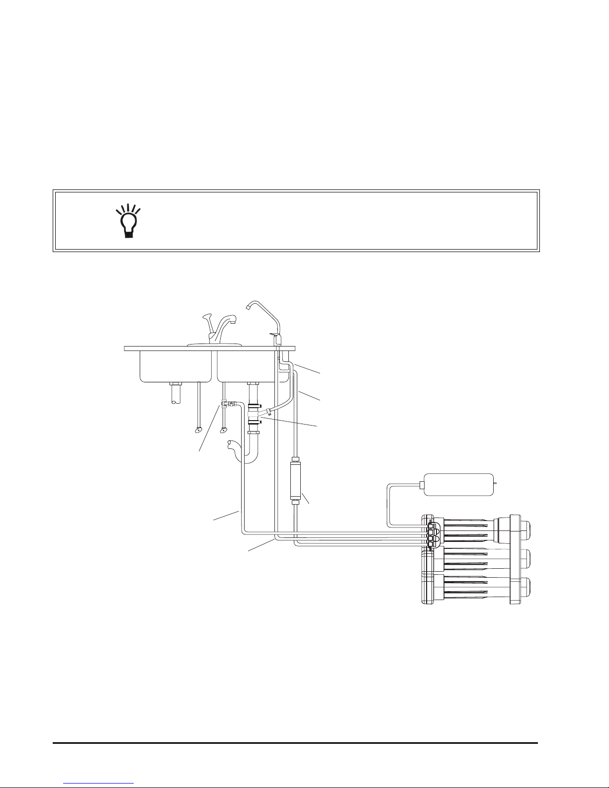
LOCATION OF SYSTEM
The reverse osmosis system is designed for installation under a sink,
usually in the kitchen or bathroom. The RO assembly can be placed on
the cabinet floor in any position that does not apply pressure on the
disconnect elbows. The RO product water faucet installs on the sink or
on the countertop next to the sink.
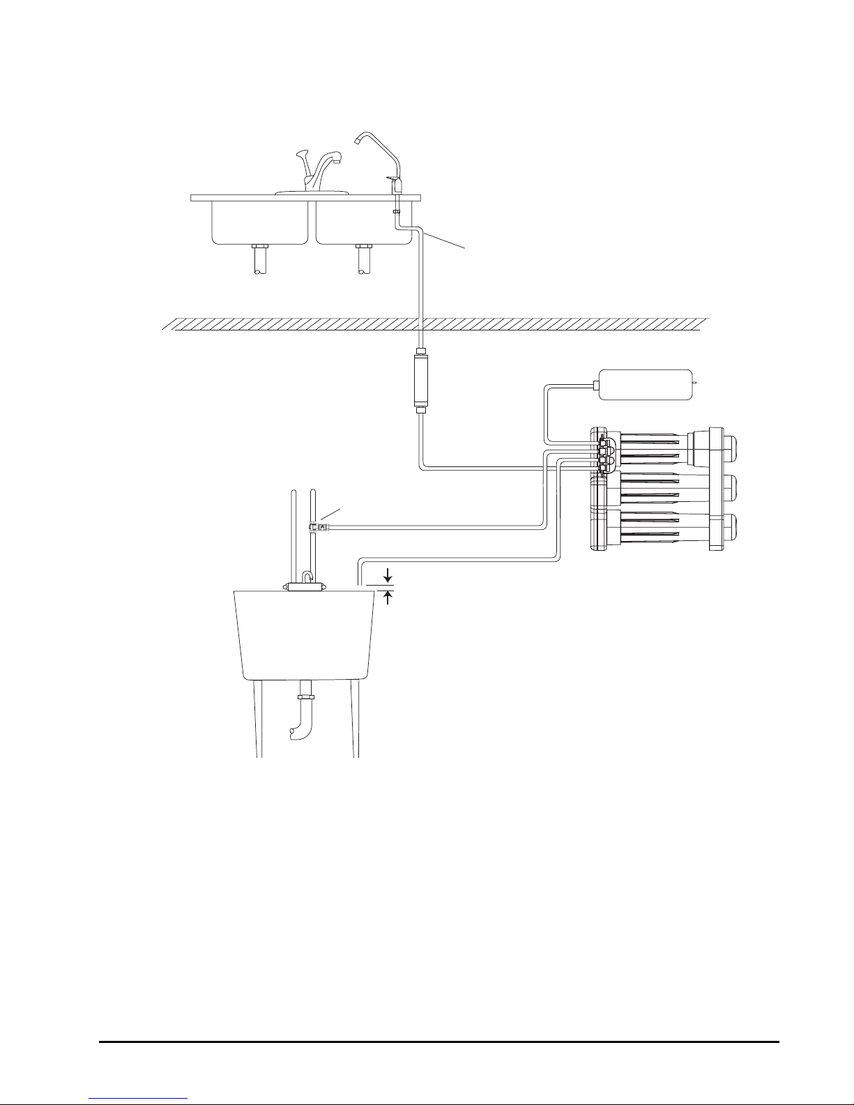
The RO system can also be located in a location away from the faucet.
A nearby water source and drain point are required.
Water Supply: To provide supply water to the RO system inlet, a feed
supply fitting is required or install pipe fittings as needed.
Drain Point: A suitable drain point is needed for reject water from the
RO system. A floor drain, laundry tub, standpipe, sump, etc. are all
acceptable. A sink p-trap drain adapter is included to install as an
optional drain point where codes permit.
All components and tubing should be located in an area which is not
exposed to freezing temperatures. Do not expose unit or tubing to
direct sunlight.
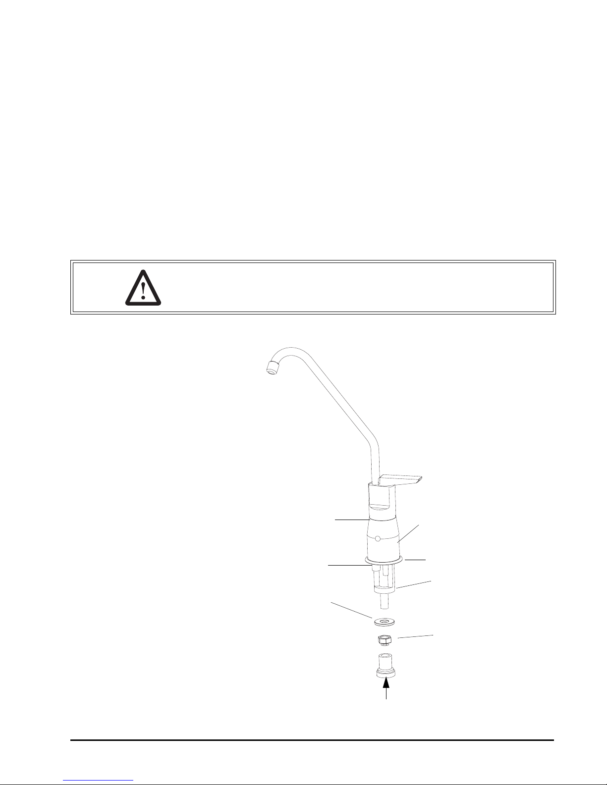
Dispensing Faucet: The faucet should be placed near the sink where
drinking water is normally obtained. Convenience of use (filling of
water pitchers and glasses) and an open area beneath the faucet
under the sink for attaching product and drain tubing are
considerations. A 2-inch diameter flat surface is required above and
below the installation site. The thickness of mounting surface should
not exceed 1-1/4 inches. Avoid any strengthening webbing on the
underside of the sink.
RO Manifold Assembly: The manifold can be installed on either the
right or left side of the under-sink area or cabinet. Installation in the
basement is also an option. One possible location is near the
laundry/utility sink where cold potable water and drain access are
close. The location chosen should allow adequate clearance and
accessibility for membrane element changes.
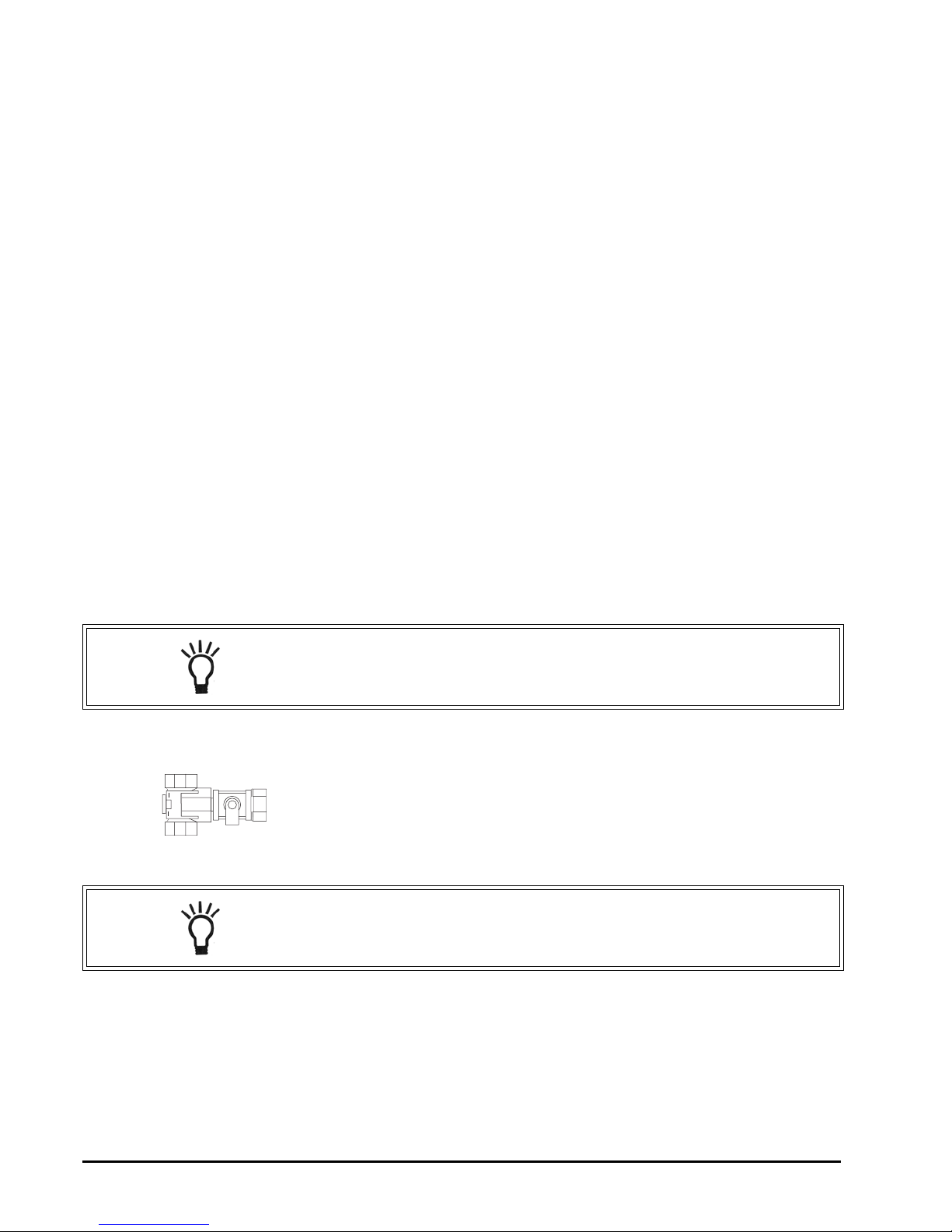
Feed Water Connection: The feed water valve should be located as
close to the manifold assembly as possible. USE A POTABLE COLD
WATER SUPPLY ONLY. Softened water is preferred as it will extend
the life of the RO membrane element.
NOTE: Keep the lengths of tubing short. Longer lengths of tubing
will decrease system performance. A booster pump can be used on
the supply line.
NOTE: The feed water connection is not included in the package.