3333
3333
33
GBGB
GBGB
GB
6 Installation6 Installation
6 Installation6 Installation
6 Installation
By the operator of the unit
Fit shut-off valves up- and downstream of the unit. The unit can be connected to
the water-supply network with commercially available fittings and stop valves.
We recommend that you connect the unit using flexible hoses, e.g. with the
connection set. Softening units with more than 90 litres of resin per bottle mustmust
mustmust
must
have flexible,have flexible,
have flexible,have flexible,
have flexible, i.e. not rigid, piping.
A multiblock module can only be installed on Rondomat Duo 2 and 3 models if
blended water is to be used (not at a residual hardness of(not at a residual hardness of
(not at a residual hardness of(not at a residual hardness of
(not at a residual hardness of
< 0.1 °d)< 0.1 °d)
< 0.1 °d)< 0.1 °d)
< 0.1 °d).
If the residual hardness is less than 0.1° d, a GIT multiblock module can be used.
Please note that there is a separate manual for the Multiblock/GIT Module and for
connection set DN 32/32.
The univalve block 11/2“ order no.: 11822 can also be used for Rondomat
6 models.
Note: Be sure to observe the arrows on the control valve that indicate theNote: Be sure to observe the arrows on the control valve that indicate the
Note: Be sure to observe the arrows on the control valve that indicate theNote: Be sure to observe the arrows on the control valve that indicate the
Note: Be sure to observe the arrows on the control valve that indicate the
direction of flodirection of flo
direction of flodirection of flo
direction of floww
ww
w.
Units 6 and 10 onlyUnits 6 and 10 only
Units 6 and 10 onlyUnits 6 and 10 only
Units 6 and 10 only
Units 6 and 10 are delivered empty and in unassembled form.
1. Position softening columns (1+21+2
1+21+2
1+2) in a suitable location (see installation
diagram), and remove the central pipes. Note!Note!
Note!Note!
Note! Do not mix up central
pipes! The length of the central pipe with the distributor is designed precisely
for the softening columns.
Make sure that the softening columns are empty and clean.
2. The distributor at the lower end of the central pipe has an alignment.
There is a counter piece at the bottom of the softener column. Place the
central column with the distributor nozzle alignment downwards on the
counter piece in the softener column. Seal the pipes using protective
caps.
Note! DurNote! Dur
Note! DurNote! Dur
Note! During filling no chips maing filling no chips ma
ing filling no chips maing filling no chips ma
ing filling no chips may fy f
y fy f
y fall under the distrall under the distr
all under the distrall under the distr
all under the distribib
ibib
ibutor nozzleutor nozzle
utor nozzleutor nozzle
utor nozzle..
..
.
TheThe
TheThe
The
control valve could break while it is being screwed on.control valve could break while it is being screwed on.
control valve could break while it is being screwed on.control valve could break while it is being screwed on.
control valve could break while it is being screwed on.
3. Put the filling cone in place and pour in the correct quantity of coarse
chip, followed by fine chip and resin, making sure that they are evenly
distributed around the central pipe. Flush in the last 1 - 2 sacks of ion
exchanger with a disinfectant solution.
Disinfectant solution preparation:
6 g powder for 10 liters of water6 g powder for 10 liters of water
6 g powder for 10 liters of water6 g powder for 10 liters of water
6 g powder for 10 liters of water
Safety note!Safety note!
Safety note!Safety note!
Safety note! Wear disposable gloves when preparing and flushing.
Filling quantity per softening columnFilling quantity per softening column
Filling quantity per softening columnFilling quantity per softening column
Filling quantity per softening column
ModelModel
ModelModel
Model CoarseCoarse
CoarseCoarse
Coarse Fine chipFine chip
Fine chipFine chip
Fine chip ResinResin
ResinResin
Resin Desinf.Desinf.
Desinf.Desinf.
Desinf.
chipchip
chipchip
chip solutionsolution
solutionsolution
solution
66
66
6 1 bag 1 bag 4 sacks approx. 40 l
= 10 l = 4 l = 100 l
1010
1010
10 1 bag 1 bag 6 sacks approx. 50 l
= 10 l = 7 l = 150 l
Refill disinfectant solution until it is approx. 2 cm above the resin.
The disinfectant solution must remain in the softening column for 1 hour.The disinfectant solution must remain in the softening column for 1 hour.
The disinfectant solution must remain in the softening column for 1 hour.The disinfectant solution must remain in the softening column for 1 hour.
The disinfectant solution must remain in the softening column for 1 hour.
The unit may not be started for at least one hour after filling.The unit may not be started for at least one hour after filling.
The unit may not be started for at least one hour after filling.The unit may not be started for at least one hour after filling.
The unit may not be started for at least one hour after filling.
4. Clean softening column upper sections and threads of resin. RemoveRemove
RemoveRemove
Remove
the protective caps from the middle pipes. Do not pull the pipes upwards.the protective caps from the middle pipes. Do not pull the pipes upwards.
the protective caps from the middle pipes. Do not pull the pipes upwards.the protective caps from the middle pipes. Do not pull the pipes upwards.
the protective caps from the middle pipes. Do not pull the pipes upwards.
5. Smear O-rings with high-quality grease (e.g. Vaseline), and screw the
control valve (33
33
3) and the adapter (44
44
4) on the softening columns, ensuring
a tight fit. The central pipes must engage in the openings sealed by the
O-rings on the control valve and adapter respectively.
Turn the softening column into the connecting position. Pull the O-rings onto
the reinforced hoses (1717
1717
17). Insert the reinforced hoses into the control valve
and adapter and secure each one with two support clamps (1818
1818
18).
Secure the controller mounting-plate
Unscrew two screws on the control valve (see below) and secure the
mounting plate using these screws. Screw the Soft-Control controller and
the transformer onto the mounting plate.
Connect the unit to the local water-supply networkConnect the unit to the local water-supply network
Connect the unit to the local water-supply networkConnect the unit to the local water-supply network
Connect the unit to the local water-supply network
The local hard and soft water pipes should be connected to the input and
output pipes on the unit respectively.
Insert the brine hose (99
99
9) into the tapered opening of the brine hose connection
(1616
1616
16) and tighten the coupling ring.
Secure the flushing-water hose (16 x 3) to the flushing-water connection
(1010
1010
10) using hose clamps. Route the hose with a natural incline to the sewage
system connection and secure against sudden pressure-induced movement.
Fasten a hose (13 x 2) around the overflow (88
88
8) of the brine container.
Secure it with hose clamps and route it with an incline to the sewage system
connection (drain). There should be no constriction of the cross section of
either hose.
Please note:Please note:
Please note:Please note:
Please note: The flushing water and overflow hoses must be routed
separately and connected to the sewage water system at least 20 mm
above the highest waste water level (unimpeded drainage).
Make electrical connections (see terminal connection diagram; 8-wire valve
block, numbered cables; salt low, water meter, transformer).
Note:Note:
Note:Note:
Note:
The poThe po
The poThe po
The poww
ww
wer supply unit fer supply unit f
er supply unit fer supply unit f
er supply unit for the control vor the control v
or the control vor the control v
or the control valvalv
alvalv
alve is constre is constr
e is constre is constr
e is constructed accordingucted according
ucted accordingucted according
ucted according
to EN 60335-1.to EN 60335-1.
to EN 60335-1.to EN 60335-1.
to EN 60335-1.
The complete poThe complete po
The complete poThe complete po
The complete poww
ww
wer supply unit mer supply unit m
er supply unit mer supply unit m
er supply unit must be replaced in eust be replaced in e
ust be replaced in eust be replaced in e
ust be replaced in evv
vv
ventent
entent
ent
of damage to the mains cable.of damage to the mains cable.
of damage to the mains cable.of damage to the mains cable.
of damage to the mains cable.
41
32
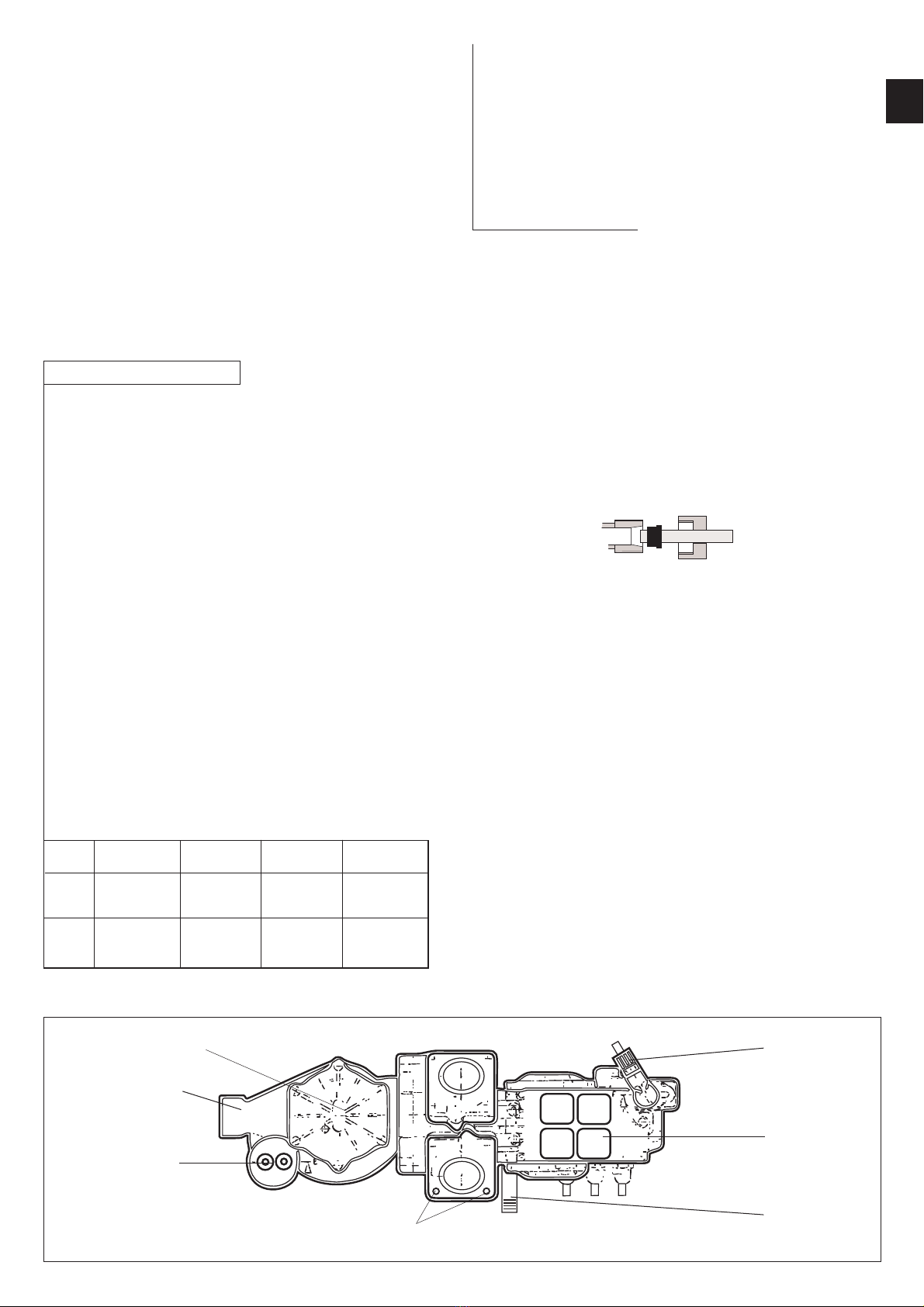
Fig. 1aFig. 1a
Fig. 1aFig. 1a
Fig. 1a
1010
1010
10
1616
1616
16
12+1312+13
12+1312+13
12+13
14+1514+15
14+1514+15
14+15
Water meterWater meter
Water meterWater meter
Water meter
SolenoidSolenoid
SolenoidSolenoid
Solenoid
valvesvalves
valvesvalves
valves
Mounting plate for Soft-Control screwedMounting plate for Soft-Control screwed
Mounting plate for Soft-Control screwedMounting plate for Soft-Control screwed
Mounting plate for Soft-Control screwed
down heredown here
down heredown here
down here