Bay Products 11352 User manual


Level 1 Service Manual
Manhole Odor Control Units
Table Of Contents
SECTION 1: GENERAL INFORMATION FOR OPERATION
AND MAINTENANCE
SECTION 2: DETAILED INSTALLATION, MAINTENANCE,
CALIBRATION AND REPAIR
SECTION 3: DIAGRAMS AND SCHEMATICS
SECTION 4: WARRANTIES, GUARANTIES AND SPARE
PARTS
See Section 2 – 2.G on Pg. 2-12 thru 2-14 for
information needed to Order Replacement Activated
Carbon Media for the Manhole Odor Control Units
SECTION 5: FIELD TESTING RECORDS
SECTION 6: EQUIPMENT DATA SHEETS

Level 1 Service Manual
Manhole Odor Control Units
Table Of Contents
SECTION 1: GENERAL INFORMATION FOR OPERATION
AND MAINTENANCE
1.A General Instructions
1.A.1 Description Of The Equipment and How It Functions
including Location Maps for each Site Area ................Pg. 1-1 thru 1-6
1.A.2 Identification Information ..............................Pg. 1-7 thru 1-12
Safety Precautions ................................................... Pg. 1-7
Manhole Odor Control Units......................Pg. 1-8 thru 1-9
Carbon Canister .................................................... Pg. 1-10
Carbon Media ........................................Pg. 1-10 thru 1-11
Backdraft Dampers ................................Pg. 1-11 thru 1-12
1.A.3 Normal Operation Information
Normal Operation – Passive Odor Control............ Pg. 1-13
1.A.4 General Assembly Drawings, Sections, or Photographic
Views
Equipment Drawing............................................... Pg. 1-14
Typical Installation of Manhole Odor Control Unit with
(Open Bilco Door) showing Backdraft Dampers and
Carbon Media Canister.......................................... Pg. 1-15

1.A.5 Dimensions, Weight, Capacity and Design Conditions
Manhole Odor Control Units................................. Pg. 1-14
Carbon Canister .................................................... Pg. 1-10
Carbon Media ........................................Pg. 1-10 thru 1-11
Backdraft Dampers ................................Pg. 1-11 thru 1-12

Manhole Odor Control Units
1.A.1 – Description of the Equipment and How it Functions
The following paragraphs provide a brief description of the nine (9) Manhole Odor Control Units
installed in the Vent Structures throughout Sites 1995, Site 4, Site 17 and Site 27:
The Manhole Odor Control Units are installed inside of the manhole vent structures and are
designed to remove malodorous compounds from the foul manhole air as it is diffused from the
vent structures. As malodorous air from the manhole enters the bottom of the carbon canister
support in each manhole, it is diffused up through the activated carbon media by the ambient
pressure in the sewer vault. As the foul air is diffused through the activated carbon media, the
odorous compounds are absorbed by the activated carbon media. The carbon canisters can be
easily removed and the carbon media can be replaced as required. The pressure drop through the
carbon canister is less than 1.0 inch water column at a velocity of 35 feet per minute.
Each Manhole Odor Control Unit is comprised of four major components: the Carbon Canister,
the Carbon Media, the Canister Support Plate, and two Backdraft Dampers.
The Carbon Canister, manufactured by Bay Products, Inc., is white in color and composed of 90-
mil thick High-Density Polyethylene (HDPE). This canister has a porous bottom with a
polypropylene carbon retention screen and a closed flat top with treated air release holes. The
Carbon Canister has a 12 inch diameter top, a 10-¾ inch diameter bottom, and is 15 inches in
height.
The Carbon Media provided within the Carbon Canister is virgin, granular, bituminous coal
derived activated carbon. Please find the table below summarizing the Carbon Media
specifications:
Carbon Media (Activated Carbon) - Specifications
Volume Supplied (ft3) 0.62
Weight Supplied (lbs) 20
Butane Activity (wt. %) 15.6 (minimum)
Hardness Number 97 (minimum)
Iodine Number (mg/g) 800 (minimum)
Ash (wt. %) 7 (maximum)
Apparent Density (g/cc) 0.56 (minimum)
Mean Particle Diameter (mm) 3.7 (minimum)
Minimum Hydrogen Sulfide (H2S) Capacity (g/cc) 0.09
1-1

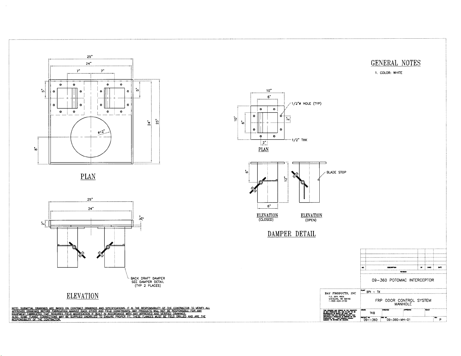
The Canister Support plate, used for holding the Carbon Canister and mounting the
Backdraft Dampers, is 24 inches in length, 24 inches in width and ½ inch in thickness
and composed of Fiberglass Reinforced Plastic (FRP).
The Backdraft Dampers (two per Manhole Odor Control Unit) are designed to allow
atmospheric air in but prevent malodorous air from leaking out of the vent structure. The
dampers are white in color, gel-coated with UV inhibitors, and are composed of AOC
K022, Vinyl Ester Resin with Class 1 Flame Spread Rating, with a 100 mil corrosion
barrier consisting of a 10 mil layer of Nexus surfacing veil, and backed with two layers of
1-½ oz. chopped strand mat. Please see the table below referencing the construction
materials of the individual components associated with the Manhole Odor Control
System Backdraft Dampers:
Backdraft Damper Components – Material Construction
Blade FRP with corrosion barrier
Bearings Graphite-filled Teflon
Axels Premium grade FRP
Hardware 316 Stainless Steel
Flanges 6” x 6” (inside diameter) for mounting to FRP plate
Face-to-face lengths 12 inches
Blade Seal EPDM
Shaft Seal EPDM O-Ring housed in the FRP flange
Bolt/Gasket Set 1/8 inch thick Neoprene gasket material with 316 Stainless Steel
bolts, 6” x 6” (inside diameter)
1-2

Site 1995 –Manhole Odor Control Systems
The below referenced table and photo summarize the locations of the Manhole Odor Control
Systems installed throughout Site 1995:
Site –1995 Manhole Odor Control Systems
Vent
Structure
Longitude (West)
Latitude (North)
Degree
Min
SS
Degree
Min
SS
VS-2
77
7
18.23
38
56
25.29
VS-3
77
7
25.49
38
56
43.57
VS-1994
77
6
5.03
38
55
5.01
1-3
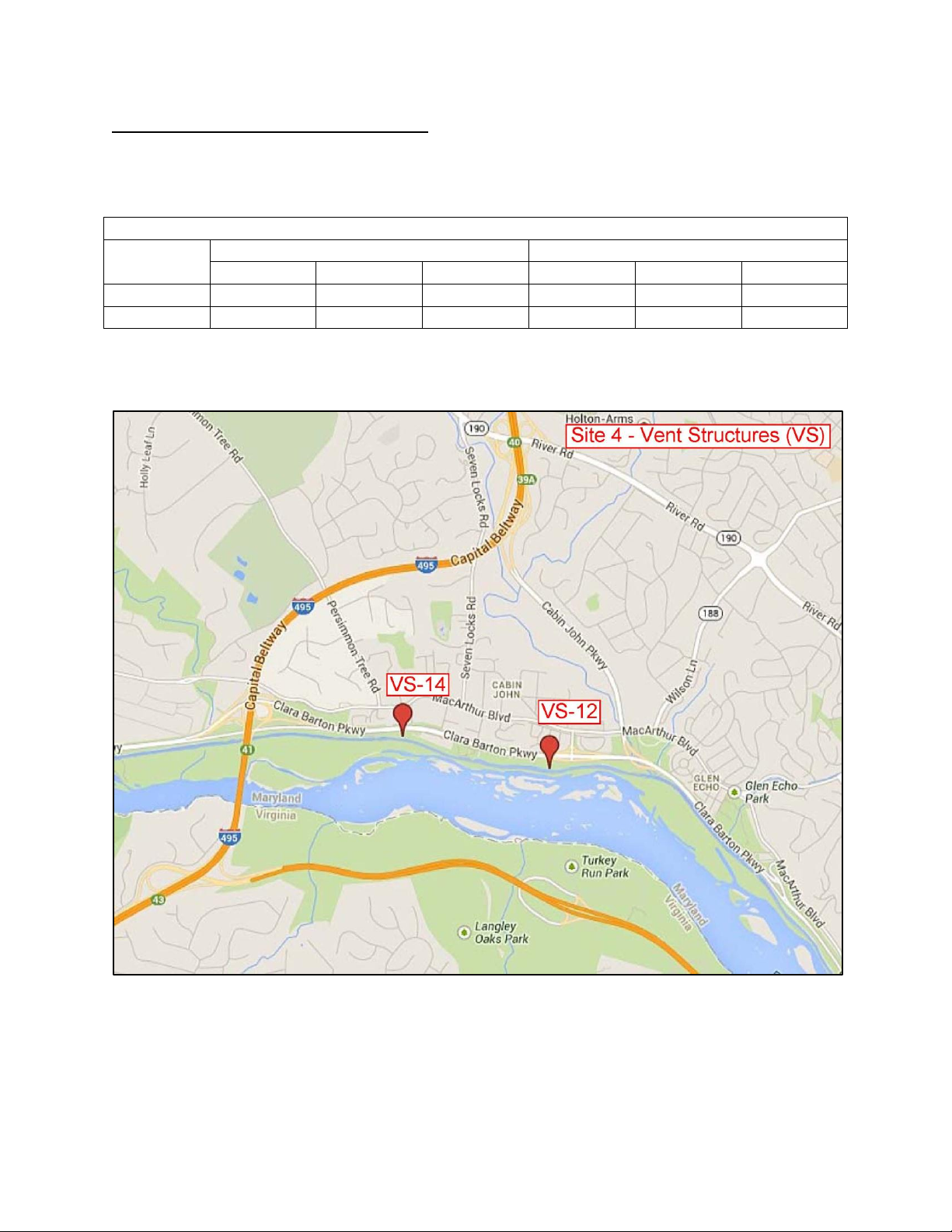
Site 4 –Manhole Odor Control Systems
The below referenced table and photo summarize the locations of the Manhole Odor Control
Systems installed throughout Site 4:
Site –4 Manhole Odor Control Systems
Vent
Structure
Longitude (West)
Latitude (North)
Degree
Min
SS
Degree
Min
SS
VS-12
77
9
16.58
38
58
13.65
VS-14
77
9
59.17
38
58
21.02
1-4

Site 17 –Manhole Odor Control Systems
The below referenced table and photo summarize the locations of the Manhole Odor Control
Systems installed throughout Site 17:
Site –17 Manhole Odor Control Systems
Vent
Structure
Longitude (West)
Latitude (North)
Degree
Min
SS
Degree
Min
SS
VS-24
77
12
22.75
38
58
40.69
VS-25
77
12
48.29
38
58
40.32
VS-26
77
13
15.3
38
58
43.91
1-5
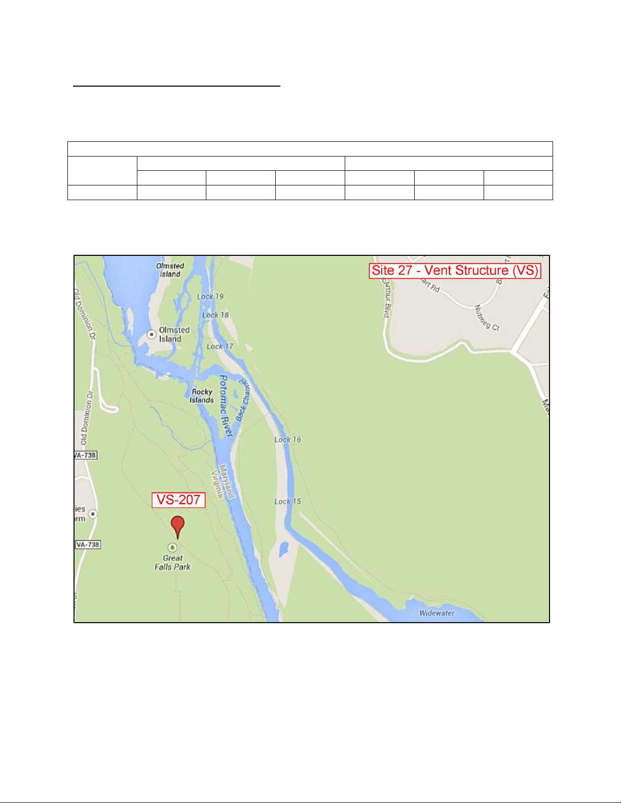
Site 27 –Manhole Odor Control System
The below referenced table and photo summarizes the location of the Manhole Odor Control
System installed on Site 27:
Site –27 Manhole Odor Control System
Vent
Structure
Longitude (West)
Latitude (North)
Degree
Min
SS
Degree
Min
SS
VS-207
77
15
1.84
38
59
15.35
1-6

ACTIVATED CARBON SAFETY PRECAUTIONS
1.A.2 Identification Information
DESCRIPTION
Activated Carbon is a Vapor Phase Virgin Activated Carbon that has been specially developed
for odor removal (adsorbtion) from sewage treatment operations. This bituminous coal based
product is unique in that it provides high adsorbtion capacity for H2S without chemical
impregnates and adsorbs volatile organic compounds (VOCs) in an effective manner.
SPECIFICATIONS
Vapor Phase Virgin Activated Carbon, Bituminous Coal based with high adsorption capacity for H2S
without chemical impregnates.
Butane Activity (wt. %) 15.6 minimum
Iodine Number - 800 minimum
H2S Capacity -(grams H2S / cc of carbon) .09 g/cc minimum
Ash (weight) 7% maximum
Apparent Density (grams / cc) .56 minimum
Hardness - 97 minimum
Mean Particle Diameter - (mm) 3.7 minimum
CAUTION: WET ACTIVATED CARBON DEPLETES OXYGEN FROM AIR
Whenever workers enter a vessel containing carbon media, all precautions must be taken
since dangerously low levels of oxygen may be encountered. Atmosphere sampling and
work procedures for potentially low oxygen areas should be followed.
The Odor Control Manhole vent structure is not an enclosed structure. It is recommended
that after opening the Bilco Hatch that all workers wait 2 minutes for the vent structure to
ventilate to the atmosphere before reaching down to replace the carbon media.
CAUTION: Used Carbon Media is Highly Acidic
Workers must wear protective gloves whenever handling the used “Spent” carbon media.
1-7

1.A.2 Identification Information
MANHOLE ODOR CONTROL UNIT
HIGHLY EFFECTIVE, PASSIVE MANHOLE ODOR CONTROL
Bay Products, MANHOLE OCU is compact, modular unit designed to remove unpleasant odors
such as hydrogen sulfide, mercaptans and other organic odors venting from sewer conveyance
manholes. The unit comes equipped with media that is specially designed to have high-activity
for use in odor control applications. The MANHOLE OCU offers the following features &
benefits:
>- Eliminates Unpleasant Odors - By removing hydrogen sulfide and organic odors from the air
stream, each MANHOLE OCU prevents unpleasant odors from entering the atmosphere around
the manhole covers.
>- No Energy Requirements - There are no mechanical parts. Unpleasant odors are removed by
adsorption from the air stream as a sewer conveyance line breathes through the manhole.
>- Flexible Treatment - Since the MANHOLE OCU is based on adsorption principles it is
passive in operation, which means it can be highly effective on changing flows and odor
concentrations.
>- Non-Corrosive - All MANHOLE OCUs are manufactured from industrial plastics that have
proven reliability in this type of service.
>- Passive Odor Control - By using positive pressures inside the sewer conveyance line,
odorous air passes up through the unit where the unpleasant odors are adsorbed and
stored in the media, allowing purified air to vent through the top of the unit into the
atmosphere. The pressure or surges of pressure with the sewer conveyance line is sufficient
to overcome the pressure drop from the media bed.
>- Cost Effective - The MANHOLE OCU is a simple media adsorption unit, which offers a high
degree of odor control and performance at a low cost.
>- Replacement Media - When odor breakthrough is detected, the media needs to be replaced.
Bay Products can provide replacement media. Media replacement is as simple as dumping out
the old media and filling with fresh media. This can be done at the site in a manner of a few
minutes.
Bay Products Inc.
P.O. Box 4859
Stateline, NV 89449-4859
phone: 800-429-0150
fax: 775-586-8501
Web Site: www.bayprod.com
1-8
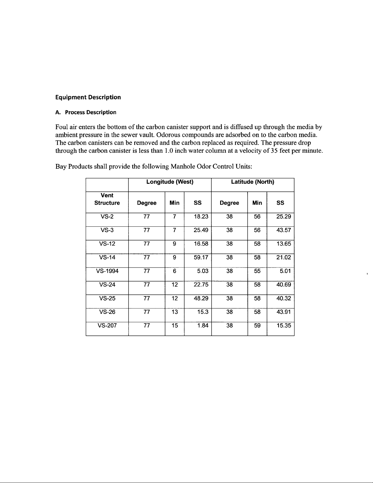
Equipment Description
A.
Process Description
Foul air enters the bottom
of
the carbon canister support and is diffused up through the media by
ambient pressure in the sewer vault. Odorous compounds are adsorbed
on
to the carbon media.
The carbon canisters can be removed and the carbon replaced as required. The pressure drop
through the carbon canister is less than 1.0 inch water column at a velocity
of35
feet per minute.
Bay Products shall provide the following Manhole Odor Control Units:
Longitude
(West) Latitude (North)
Vent
Structure
Degree Min
55
Degree Min
55
VS-2 77 7 18.23 38 56 25.29
VS-3 77 7 25.49 38 56 43.57
VS-12
77
9 16.58 38 58 13.65
VS-14 77 9 59.17 38 58 21.02
VS-1994 77 6 5.03 38
55
5.01
VS-24 77
12
22.75 38 58 40.69
VS-25 77
12
48.29 38 58 40.32
VS-26 77 13 15.3 38
58
43.91
VS-207 77 15 1.84 38
59
15.35
1-9
1.A.2 Identification Information
B. Canister Support Plate
SEE NEXT PAGE

1-10
B. Canister Support Plate

1-11
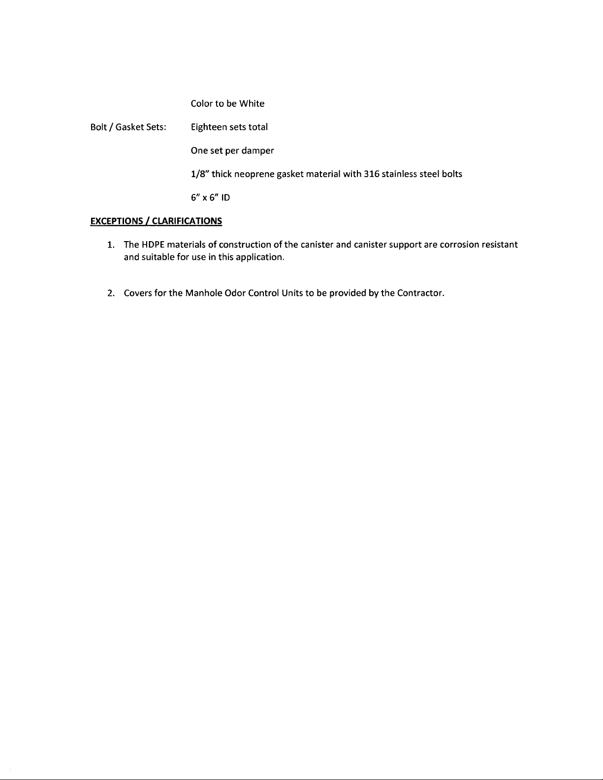
Color
to
be
White
Bolt / Gasket
Sets:
Eighteen sets total
One set per damper
1/8"
thick neoprene gasket material
with
316 stainless steel bolts
6" x 6"
ID
EXCEPTIONS
I
CLARIFICATIONS
1. The
HDPE
materials
of
construction
of
the canister and canister support are corrosion resistant
and suitable
for
use in this application.
2.
Covers
for
the
Manhole Odor Control Units
to
be
provided by
the
Contractor.
1-12

1.A.3NormalOperationInformation
MANHOLE ODOR CONTROL UNIT
HIGHLY EFFECTIVE, PASSIVE MANHOLE ODOR CONTROL
Bay Products, MANHOLE OCU is compact, modular unit designed to remove unpleasant odors
such as hydrogen sulfide, mercaptans and other organic compounds venting from sewer
conveyance manholes. The unit comes equipped with media that is specially designed to have
high-activity for use in odor control applications. The MANHOLE OCU offers the following
features & benefits:
>- Eliminates Unpleasant Odors - By removing hydrogen sulfide and other organic compounds
causing odors from the air stream, each MANHOLE OCU prevents unpleasant odors from
entering the atmosphere around the manhole covers.
>- No Energy Requirements - There are no mechanical parts. Unpleasant odors are removed by
adsorption from the air stream as a sewer conveyance line breathes through the manhole.
>- Flexible Treatment - Since the MANHOLE OCU is based on adsorption principles it is
passive in operation, which means it can be highly effective on changing flows and odor
concentrations.
>- Non-Corrosive - All MANHOLE OCUs are manufactured from industrial plastics that have
proven reliability in this type of service.
>- Passive Odor Control - By using positive pressures inside the sewer conveyance line, odorous
air passes up through the unit where the unpleasant odors are adsorbed and stored in the media,
allowing purified air to vent through the top of the unit into the atmosphere. The pressure or
surges of pressure with the sewer conveyance line is sufficient to overcome the pressure drop
from the media bed.
>- Cost Effective - The MANHOLE OCU is a simple media adsorption unit, which offers a high
degree of odor control and performance at a low cost.
>- Replacement Media - When odor breakthrough is detected, the media needs to be replaced.
Bay Products can provide replacement media. Media replacement is as simple as dumping out
the old media and filling with fresh media. This can be done at the site in a manner of a few
minutes.
Bay Products Inc.
P.O. Box 4859
Stateline, NV 89449-4859
phone: 800-429-0150
fax: 775-586-8501
1-13
1-14
Counterweight
inspection point
Damper inspection
point
Carbon Cannister

1.A.4 General Assembly Drawings, Sections, or Photographic Views
View of typical Manhole Odor Control Unit (Bilco Cover Opened) showing two square openings
for the Backdraft Damper Air intakes, and the Activated Carbon Canister (5 Gallon Bucket).
1-15
Backflow Damper
Carbon Cannister

Level 1 Service Manual
Manhole Odor Control Units
Table Of Contents
SECTION 2: DETAILED INSTALLATION, MAINTENANCE,
CALIBRATION AND REPAIR
2.A Installation
2.A.1 Reference Drawings or Schematics To Assemble and Install
..........................................................................Pg. 2-1 thru 2-2
2.A.2 Equipment Alignment, Clearances, Tolerances, and
Interfacing ...................................................................... Pg. 2-1
2.A.3 Identify Trade Skill Level Required To Install ............. Pg. 2-3
2.A.4 Specify Any Special Rigging Required......................... Pg. 2-3
2.A.5 Specify Any Special Test Equipment Required............ Pg. 2-3
2.B Safety
2.B.1 Identify All Safety and Tag-out Procedures.....Pg. 2-3 thru 2-4
2.C Lubrication
2.C.1 Identify Lubrication Points............................................ Pg. 2-4
Table of contents


