LTI MOTION MotionOne CM Owner's manual

SystemOne CM –CNC

2
MotionOne CM
G&M Code Programming Manual
Id.-Nr.: 1400.210B.0-01 ▪Stand: 04/2018
MotionOne CM G&M Code Programming Manual
Id.-Nr.: 1400.210B.0-01 ▪Stand: 04/2018
Valid for G&M Code version since: V 6.06.04.00
Doc version: V 7.00.00.01
The German version is the original of this manual.
All rights are reserved with respect to the content of this documentation and the availability to
the product.
Copyright ©
All content of the documentation, in particular the text, photographs and graphics it contains
are protected by copyright. The copyright lies, unless otherwise expressly stated, with
LTI Motion GmbH.
We reserve the right to make technical changes.
The content of this documentation was compiled with the greatest care and attention, and
based on the latest information available to us. We should nevertheless point out that this
document cannot always be updated in line with ongoing technical developments in our
products. Information and specifications may be subject to change at any time. For information
on the latest version please visit www.lti-motion.com.
LTI Motion GmbH LTI Motion GmbH
Schlätterstraße 2 Gewerbestraße 5-9
88142 Wasserburg/Bodensee 35633 Lahnau
Germany Germany
Fon +49 8382 9855-0 Fon.: +49 6441 966-0
Fax +49 8382 9855-50 Fax: +49 6441 966-137
info@lti-motion.com info@lti-motion.com
www.lti-motion.com www.lti-motion.com

MotionOne CM
3
G&M Code Programming Manual
Id.-Nr.: 1400.210B.0-01 ▪Stand: 04/2018
Content
General information................................................................................................................................................................5
Notes and symbols.......................................................................................................................................................5
Address letters.............................................................................................................................................................5
Axis numbers...............................................................................................................................................................5
Axis code word (AKW)..................................................................................................................................................6
Components of a NC program.................................................................................................................................................7
M Functions.............................................................................................................................................................................8
G Functions .............................................................................................................................................................................9
General explanations....................................................................................................................................................9
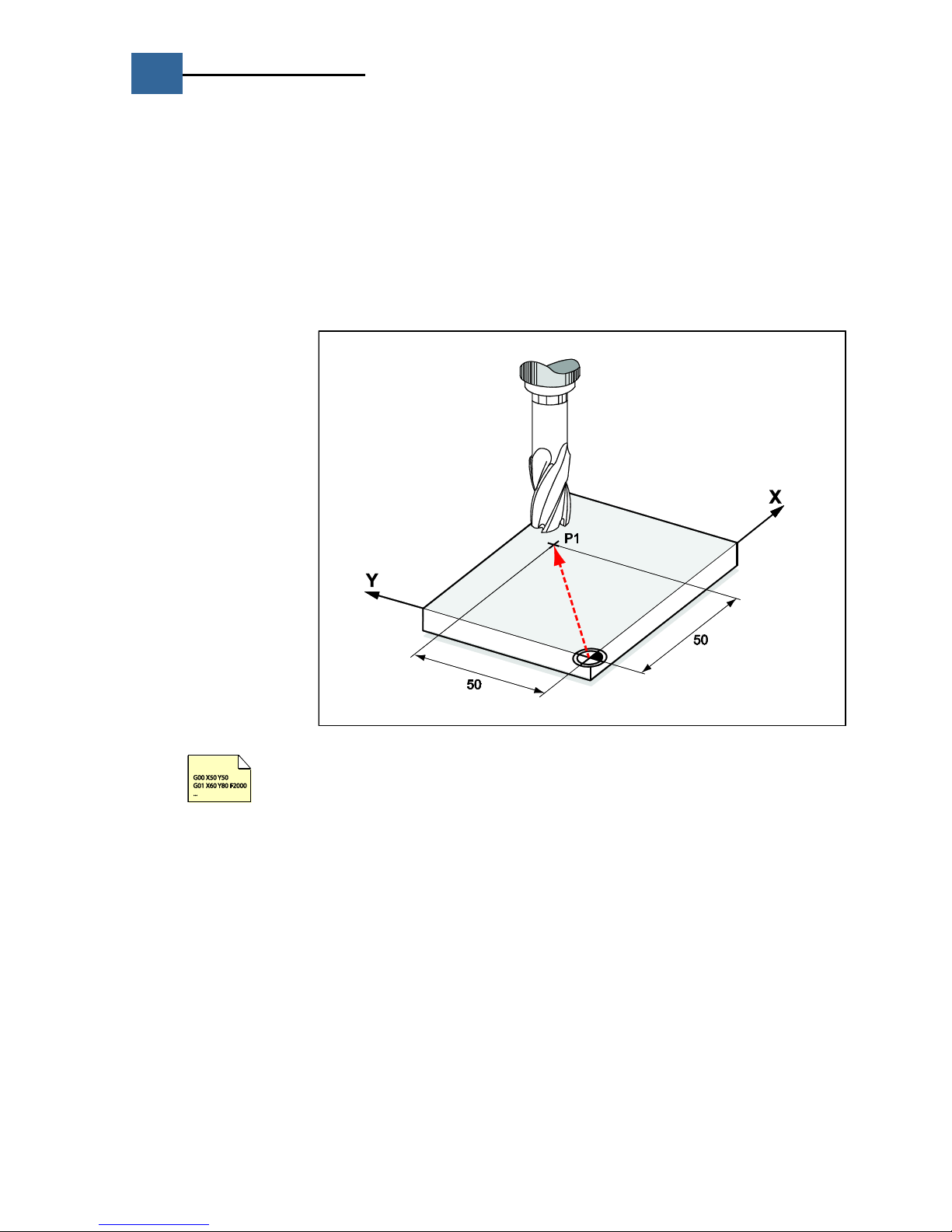
G00 Positioning in rapid traverse................................................................................................................................. 10
G01 Positioning at the feed rate.................................................................................................................................. 11
G02 Circular interpolation - Clockwise.......................................................................................................................... 12
G03 Circular interpolation - Counterclockwise............................................................................................................... 12
G04 Dwell time .......................................................................................................................................................... 13
G05 Spatial arc interpolation ....................................................................................................................................... 14
G14 Macro call ........................................................................................................................................................... 15
G17 Plane XY............................................................................................................................................................. 16
G18 Plane ZX............................................................................................................................................................. 16
G19 Plane YZ............................................................................................................................................................. 16
G22 Sub program call................................................................................................................................................. 17
G23 Text - Functions.................................................................................................................................................. 18
G25 RTCP.................................................................................................................................................................. 19
G26 Free plane .......................................................................................................................................................... 22
G27 Tool zero point.................................................................................................................................................... 24
G30 Spline interface (online spline) ............................................................................................................................. 26
G40 Deletion of the milling cutter radius correction ...................................................................................................... 27
G41 Milling cutter radius correction left ....................................................................................................................... 27
G42 Milling cutter radius correction right ..................................................................................................................... 28
G43 Milling cutter radius correction up to..................................................................................................................... 29
G44 Milling cutter radius correction via........................................................................................................................ 30
Zero offsets and coordinate rotation............................................................................................................................ 31
G53 Deletion of the zero offset ................................................................................................................................... 32
G70 Units of measurement inch .................................................................................................................................. 33
G71 Units of measurement mm................................................................................................................................... 33
G72 Deletion of mirror image machining and scaling .................................................................................................... 33
G73 Mirror image machining....................................................................................................................................... 34
G73 Scaling ............................................................................................................................................................... 35
G79 Cycle execution................................................................................................................................................... 36
G90 Absolute measure ............................................................................................................................................... 37
G91 Relative measure ................................................................................................................................................ 38
G92 Relative zero point offset coordinate rotation ........................................................................................................ 39
G93 Absolute zero point offset coordinate rotation ....................................................................................................... 40
G94 Speed programming............................................................................................................................................ 42
G95 Time programming.............................................................................................................................................. 43
G107 Eroding: Define the directional vector for the lift-off movement............................................................................ 44
G181 Probe calibration ............................................................................................................................................... 45
G190 Absolute circle center ........................................................................................................................................ 46
G191 Relative circle center ......................................................................................................................................... 47
G288 Set Look Ahead parameters ............................................................................................................................... 48
G288,0 Look Ahead basic parameter................................................................................................................... 48
G488 Simple measurement block ................................................................................................................................ 49
G488,1 Simple measurement block ............................................................................................................................. 53
G581 Continuous operation cycle rotation.................................................................................................................... 54
G781,1 Spindle offset ................................................................................................................................................. 55
G783,0 Read/Write zero points ................................................................................................................................... 56
G1000 Eroding: Velocity ............................................................................................................................................. 57
G1001 Eroding: Directions .......................................................................................................................................... 58
G1002 Eroding: Factors and modes............................................................................................................................. 59
G1003 Eroding: Time data.......................................................................................................................................... 60
G1004 Eroding: Orbital movement in the selected plane............................................................................................... 61

4
MotionOne CM
G&M Code Programming Manual
Id.-Nr.: 1400.210B.0-01 ▪Stand: 04/2018
Parameter programming ......................................................................................................................................................62
Flexible G&M code Programming (FlexProg)........................................................................................................................63
General ..................................................................................................................................................................... 63
Restrictions................................................................................................................................................................ 64
General program structure.......................................................................................................................................... 64
Data types................................................................................................................................................................. 64
Functions (general) .................................................................................................................................................... 65
Function declaration................................................................................................................................................... 65
Macros and Q parameters.......................................................................................................................................... 65
Function definition ..................................................................................................................................................... 66
Variables ................................................................................................................................................................... 66
Communication variables............................................................................................................................................ 67
Expressions and operators.......................................................................................................................................... 68
Mathematical functions............................................................................................................................................... 68
Assignment of NC addresses....................................................................................................................................... 69
Comment marks......................................................................................................................................................... 69
Point definition........................................................................................................................................................... 69
Instructions ............................................................................................................................................................... 70
Jump marks............................................................................................................................................................... 70
GOTO/IF ... GOTO/ IF ELSE........................................................................................................................................ 70
FOR loops.................................................................................................................................................................. 71
WHILE loops.............................................................................................................................................................. 71
DO ... WHILE loops .................................................................................................................................................... 71
SWITCH ... CASE branching........................................................................................................................................ 72
Sample programs....................................................................................................................................................... 73
Index ....................................................................................................................................................................................78
Revisions...............................................................................................................................................................................80

MotionOne CM
5
G&M Code Programming Manual
Id.-Nr.: 1400.210B.0-01 ▪Stand: 04/2018
General information
Notes and symbols
This description uses the following symbols:
Important notes, information or cross references to other descriptions.
This symbol indicates an example.
Address letters
Character
Function
N
Block number
G
Path condition
A, B, C
Path information A axis, B axis, C axis
X
Path information X axis, dwell time
Y, Z
Path information Y axis, Z axis
I, J, K
Interpolation parameters, circle center
F
Feed rate, time for G95 (inverse time programming)
O
Output address
D
Additional information (cutting edge correction table)
E
Additional information on the PLC
S
Spindle speed
T
Tool number
M
Machine function
W
Command extension
Axis numbers
Axis
Number
Axis
Number
A
0
X‘
8
X
1
Y‘
9
Z
2
P
10
Y
3
Q
11
B
4
R
12
C
5
U
13
D
6
V
14
E
7
W
15

6
MotionOne CM
G&M Code Programming Manual
Id.-Nr.: 1400.210B.0-01 ▪Stand: 04/2018
Axis code word (AKW)
The cycle call-up parameters do not allow all axis letters of the andronic to be specified. This is why
for some cycles the axis values other than XYZABC must be specified by means of a list containing the
values for the individual axes and by means of an axis code. The axis code word describes for which
axes valid values have been specified.
Note:
To determine the axis code, the program WINAKW.exe in the directory C:/andron/tools
or the following table in which the example is shown for the axes X, Y and Z can be used.
The program
WINAKW.exe
to determine
the axis code
The example shows how to specify values for X Y Z U V W.
FKV[1] = 45.5
FKV[3] = 15.5
FKV[2] = 43.5
FKV[13] = 45.7
FKV[14] = 5.5
FKV[15] = 4.6
Gxxx K57358
; Specify value for X
; Specify value for Y
; Specify value for Z
; Specify value for U
; Specify value for V
; Specify value for W
; Call cycle via axis code K (AKW decimal, see picture)

MotionOne CM
7
G&M Code Programming Manual
Id.-Nr.: 1400.210B.0-01 ▪Stand: 04/2018
Components of a NC program
The sequence of a machining process on the machine is described by the NC program. It consists
mainly of a sequence of program records. In a program record all the necessary information for a
work step are included. Record numbers can be entered under the address N.
With the andronic control, the programming is also permissible without block numbers.
With program words, as a general principle, a differentiation is made between modal (latching) and
non-modal words. A word is modal if its value remains effective until it is overwritten by another
value, or the end of the program has been reached. In contrast, non-modal words only have an effect
within the block in which they have been programmed.
The following can be programmed within a block.
Character
Function
N
Block number (optional)
G
Path condition
A
Path information A axis
B
Path information B axis
C
Path information C axis
X
Path information X axis, dwell time
Y
Path information Y axis
Z
Path information Z axis
I, J, K
Interpolation parameters, circle center
F
Feed speed, dwell time, time display at G95 (Invers Time Programming)
O
Output address
D
Auxiliary information (correction memory)
E
Additional information on the PLC
S
Spindle speed
T
Tool number
M
Machine function
W
Command extension
G02 X50 Y0 I25 J0 F2000 S10000 M3 T7 M6
G02
Path condition circle in clockwise direction
X50
X coordinate
Y0
Y coordinate
I25
Auxiliary parameter circle center X coordinate
J0
Auxiliary parameter circle center Y coordinate
F2000
Feed speed 2000 mm/min
S10000
Spindle speed 10000 1/min
M03
Machine function 'Spindle on'
M06
Machine function 'Change tool'
Special characters
%
The rest of the line is interpreted as a comment
;
The rest of the line is interpreted as a comment
[ ]
Jump mark, index at FlexProg
/*...*/
Encapsulated comment at FlexProg
( )
Comment, function bracket at FlexProg

8
MotionOne CM
G&M Code Programming Manual
Id.-Nr.: 1400.210B.0-01 ▪Stand: 04/2018
M Functions
Note:
The M functions initiate certain machine functions. These functions may differ depending on machine
type/manufacturer.
General M functions
M
Function
C.*
M00
Programmed stop
1
M01
Optional stop
1
M02
End of program
1
M19
Spindle stop with defined end position
1
M30
End of program with spindle 0 Off
1
M functions for control type
eroding "EROD"
M
Function
C.*
M92
Lift-off via programmed direction vector (G107 …)
2
M93
Delete last retraction point
2
M94
Spark erosion function AFC OFF, no forward and backward interpolation
2
M95
Spark erosion function AFC ON
2
M96
Retreat on the path ON
2
M97
Retreat via points ON
2
M98
Saving the actual position as a retraction point
2
M800
Switching off collision protection via NC program
2
M801
Switch collision protection on again
2
M802
Modulo formation off
2
M802
Modulo formation on
2
M900
Activate sparking out
2
* Comments on the M commands:
1
Function is effective at end of block
2
Function is effective at start of block

MotionOne CM
9
G&M Code Programming Manual
Id.-Nr.: 1400.210B.0-01 ▪Stand: 04/2018
G Functions
General explanations
Property:
MODAL means that the command/function remains active until it is overwritten.
Topic:
The G functions can be divided into the following topics:
interpolation type
special command
setup command
tool command
cycle command
eroding command
Position:
DEF = Default (active after starting the control unit)
--- = Not pre-set

10
MotionOne CM
G&M Code Programming Manual
Id.-Nr.: 1400.210B.0-01 ▪Stand: 04/2018
G00 Positioning in rapid traverse
Property
modal
Topic
Axis movement
Position
---
Syntax
G00
The path information G00 programs rapid traverse movements by specifying the target point. The
target point is reached by entering it either in absolute or relative dimensions. The rapid traverse
speed can be defined in the MotionCenter.
G00 X50 Y50 ; The axes are moved by interpolation to point P1

MotionOne CM
11
G&M Code Programming Manual
Id.-Nr.: 1400.210B.0-01 ▪Stand: 04/2018
G01 Positioning at the feed rate
Property
modal
Topic
Axis movement
Position
DEF
Syntax
G01
The path information G01 programs feed movements by specifying the target point. The target point
is reached by entering it either in absolute measure or relative measure. The feed rate can be defined
in the MotionCenter or programmed by means of the F parameter.
G01 X50 Y50 F2000 ; Positioning at point P1 at 2000 mm/min

12
MotionOne CM
G&M Code Programming Manual
Id.-Nr.: 1400.210B.0-01 ▪Stand: 04/2018
G02 Circular interpolation - Clockwise
G03 Circular interpolation - Counterclockwise
Property
modal
Topic
Axis movement
Position
---
Syntax
G02 /G03 <Parameter list>
For the circular interpolation, the axes are moved on an arc from the starting point to the end point.
The movement can take place clockwise by selecting G03 and counterclockwise by selecting G03.
Circular interpolation must contain the following parameters and can be applied in all 3 planes (see
G17 - G18):
G02 or G03 (direction of rotation), end point of the arc, radius of the circle (R) or circle center (I, J,
K) The center of the arc can be specified in absolute (G190) or relative (G191) coordinates. As an
alternative to the center, the radius can be programmed directly by entering the address letter R.
However, this only applies to arcs having an angle of rotation of less than 180°.
G01 X0 Y0 ; Starting point approach
G02 X0 Y0 I20 J0 ; Clockwise travel to X0 Y0. Circle center at X20 Y0 (A)
G03 X0 Y0 I-20 J0 ; Counterclockwise travel to X0 Y0. Circle center at X-20 Y0 (B)
G02 X0 Y-40 R20 ; Clockwise travel to X0 Y-40. Radius 20 mm (C)

MotionOne CM
13
G&M Code Programming Manual
Id.-Nr.: 1400.210B.0-01 ▪Stand: 04/2018
G04 Dwell time
Property
Non modal
Topic
NC command
Position
---
Syntax
G04 <Parameter list>
Unit
Seconds
Dwell time
The function G04 allows you to program a dwell time. The time is specified by the parameter X. The
function is only effective blockwise. G04 must stand alone in an NC program line
For synchronization of FlexProg calculation and motion, G04 can be used, since a contour interruption
takes place. This also applies to the dwell time X0.
Address
Value range
Unit
Accuracy
X
0 sec –2 years
Default 0
sec
Standard: 0.01 sec
LPN: 10 nsec
LPN
If the control has been equipped with an LPN card and pulsing has been activated via "G1010 O1",
the dwell time will be executed at higher accuracy. The time can then be programmed to the nearest
10ns, i.e., the smallest value is 0.00000001 seconds. During this time, the pulses are output to the P
output of the LPN card with a predefined pulse width. For laser application, this function is called
"stationary pulsing" or "piercing".
Value range: 0 –4 500 000 sec
G04 X11.4
G04 X0
G04
; Dwell time 11.4 seconds
; Dwell time 0 seconds
; Contour interruption

14
MotionOne CM
G&M Code Programming Manual
Id.-Nr.: 1400.210B.0-01 ▪Stand: 04/2018
G05 Spatial arc interpolation
Property
modal
Topic
Axis movement
Position
---
Syntax
G05 <Parameter list>
This function allows you to describe a spatial arc (spatial circle section). No information such as radius
or direction of rotation exists for this function.
An G&M code for spatial arc interpolation must contain the following parameters:
G05, end point of the spatial arc in X, Y and Z (A), intermediate point on the spatial arc in I, J and K
(B). The starting point (C) of the spatial arc is determined by the current axis position.
G01 X0 Y0 Z0 ; Starting point approach
G05 X50 Y50 Z0 I20 J30 K30 ; End point at X50 Y50 Z0
; Intermediate point at X20 Y30 Z30

MotionOne CM
15
G&M Code Programming Manual
Id.-Nr.: 1400.210B.0-01 ▪Stand: 04/2018
G14 Macro call
Property
non-modal
Topic
Special command
Position
---
Syntax
G14 N = [“] Macro name [“] [Pn]
A macro is a closed program part that must be programmed only once. A macro is not executed until
it is defined or called by the main program or another macro. In contrast to the genuine
subprograms, macros are incorporated in the program text. A macro starts with a header in which the
name of the macro is defined. No other instructions (not even block numbers) may be programmed in
the header. The name of the macro must not contain more than 24 characters and stands between
the character #. The end of the macro definition is marked by a block containing the instruction ##.
Here, too, no other instructions may be programmed.
#Rectangle# ; Header containing the name of the macro
G01 X0 Y0 F2000 ; Instructions
X100
Y100
X0
Y0
## ; End identifier
The optional inverted comma characters [“] at the beginning and end of the name only have to be
entered if the name of the macro contains symbols or blanks. The optional address letter 'P', followed
by a number, indicates how many times the macro is to be executed. The maximum number of
repetitions is: 256
If a macro has been defined as described above, it can be called in the program as follows.
G14 N = Rectangle P3 ; Example macro called three times

16
MotionOne CM
G&M Code Programming Manual
Id.-Nr.: 1400.210B.0-01 ▪Stand: 04/2018
G17 Plane XY
G18 Plane ZX
G19 Plane YZ
Property
modal
Topic
Setup command
Position
Preset G17
Syntax
G17 / G18 / G19
ATTENTION:
G18 in the CNC is not according to the DIN 66025.
The use of G18 according to DIN 66025 can be activated in the XPanel user
interface –Service –F6-System programs –F4-System configuration –G&M
converter –„G18 according to DIN 66025“.
NOTE:
A change of plane via G17/G18/G19 does not cancel active zero offsets.
NOTE:
A change of plane with G17/G18/G19 does not cancel an active rotation.

MotionOne CM
17
G&M Code Programming Manual
Id.-Nr.: 1400.210B.0-01 ▪Stand: 04/2018
G22 Sub program call
Property
non-modal
Topic
Special command
Position
---
Syntax
G22 N = [“] Program name [“] [Pn]
G22 N = [“] Database path:Program name [“] [Pn]
Programs that must be repeated several times can be called from a main program by entering G22.
This program is available as a separate NC program in the same database as the calling main
program. If the program to be called is not included in the program database of the control, the
database path must also be specified. Enter the designation from "Programs / data base:" to call the
database path in the XPanel.
Example:
G22 n="C01:ncprg_name" is loading from the user database path 1
G22 n="S05: ncprg_name" is loading from the system database path 5
The program name may contain 24 characters maximum. The optional inverted comma characters [“]
at the beginning and end of the name only have to be entered if the program name contains symbols
or blanks. The optional address letter 'P', followed by a number, indicates how many times the
program is to be executed. The maximum number of repetitions is: 32534
G22 N = Feed program P3 ; Feed program called three times

18
MotionOne CM
G&M Code Programming Manual
Id.-Nr.: 1400.210B.0-01 ▪Stand: 04/2018
G23 Text - Functions
Property
non-modal
Topic
NC command
Position
---
Syntax
G23 N = “Text “ P<Type> I<Index>
The command G23 can be used to call up different functions with ASCII texts. The target is always to
transmit a text with a length of 80 characters to the PLC, CNC or the display.
Type - P
Command
Index - I
3
Transfer text to the XPanel user interface
1-3 (Default: 1)
4
Redefines the measuring log file names of the measuring
cycles "mprot.log". If no path is specified, the data are
transmitted to %andronroot%\System\
(C:\Andron\System\*). Specified paths are not created by
the CNC and must already exist at program start.
not necessary
5
Writes the values of the communication variables into a log
file.
The name for the log file is specified according to the same
rules as for P=4, whereby the database path of the current
G&M code program is used as standard.
IKV index
0 –999
Default: 0
G23 P3 N=“Finishing part1“
Text is displayed in the prompt of the XPanel position
menue in line 1.
G23 P3 N=“ Finishing part1“ I1
Text is displayed in the prompt of the XPanel position
menue in line 1.
G23 P3 N=“ Finishing outside“ I2
Text is displayed in the prompt of the XPanel position
menue in line 2.
G23 P4 N =“C:\Messung_123.log“
Beginning with this program line, the measuring cycles
of the log file will be named with the specified
designation C01: and the path specification and no
longer with "C:\andron\ SystemData\Repository\Local
Control\Measuring Protocol\mprot.log"
IKV[100] = 156
G23 P5 N =“C:\Daten_123.log“ I100
The value of IKV[100] is written into the log file
"C:\andron\SystemData\Repository\Cycles\Measuring
Protocol\Daten_123.log".

MotionOne CM
19
G&M Code Programming Manual
Id.-Nr.: 1400.210B.0-01 ▪Stand: 04/2018
G25 RTCP
Property
modal
Topic
Transformation command
Position
---
Syntax
G25 <Parameter list>
RTCP describes the functionality of keeping a (TCP - Tool Center Point) constant during the move-
ment of rotatory axes. Despite the use of rotatory axes, the position of the TCP relative to the work-
piece does not change. RTCP normally effects a compensation movement of the corresponding axes if
one of the rotary axes is moved.
RTCP can be switched on/off with the H parameter to G25. The storing and restoring of RTCP states
is administered specifically to the program, i.e. if RTCP is deactivated in the sub-program but the
state RTCP active was stored in the main program, the state RTCP is actively restored after returning
from the sub-program and the RTCP command.
G-Befehl
Bezeichnung
Bedeutung
G25 H0
Switch off RTCP
RTCP is deactivated
G25 H1
Switch on RTCP
RTCP is activated according to the kinematics of the
machine defined in the machine parameters.
G25 H2
Save RTCP state
The state of RTCP (ON/OFF) is stored in the buffer,
e.g. to be used with tool change NC sets
G25 H3
Restore RTCP state
The state of RTCP (ON/OFF) stored in the buffer is
restored, e.g. with a temporary deactivation in the tool
change NC sets

20
MotionOne CM
G&M Code Programming Manual
Id.-Nr.: 1400.210B.0-01 ▪Stand: 04/2018
Functional description
Axis traverse movement in
milling lengthwise axis
direction
The use of axis traverse movement in milling lengthwise axis direction is possible by defining the
cinematic models regardless of an activated transformation.
Activation/deactivation must be realised by adaptations in the PLC software:
1. On/Off button
2. LED ON for active / LED OFF for inactive
3. Flashing LED for invalid selection or selection not acknowledged by the CNC
Selection of traverse movement in milling lengthwise axis direction via this key on the machine
operating panel in manual mode (not MDI, not AUTOMATIC interruption!).
The traverse movement is carried out by pressing the traverse movement keys in positive or negative
direction (+/- and selection of the corresponding fixed path 1mm, 0.1mm, 0.01mm, 0.001mm or free
movement via the +/- keys or the hand wheel). A negative traverse path is preset by a movement to
the tool tip and a positive traverse path is preset by a movement to the tool shank.
Moving in the milling lengthwise axis direction is not possible in the automatic mode.
Activation and deactivation of
5-axis transformation
The status of the transformation is displayed in the status area in the top right corner on the XPanel
with the text "G25 RTCP” on an icon.
Activation in the manual mode is possible by pressing the corresponding key. Activation in the MDI
and automatic mode is also possible by entering G25 H1.
In the position display, the position in the programming coordinate system (PROG system) is always
shown on the display of the control positions. Upon activation or deactivation, the coordinates move
depending on the position of the rotatory axes.
G25 H1
G25 H0
RTCP can be activated and deactivated as often as required within an G&M code program.
Behaviour upon NC RESET
If RTCP is active, it also remains active after an NC RESET.
Table of contents