Bayside LAGOON User manual

V1.0 Muti –EU WS (01/2019)
BAYSIDE
LAGOON
CEILING FAN
INSTALLATION
OPERATION
MAINTENANCE
WARRANTY INFORMATION
CAUTION
READ INSTRUCTIONS CAREFULLY FOR SAFE
INSTALLATION AND FAN OPERATION.

Lagoon Fan Installation Instructions
1 | P a g e
CONTENTS
GB
Installation instruction manual ...........................................................................................2
D
Installationsanleitung ........................................................................................................10
F
Guide d’installation............................................................................................................20
E
Manual de instrucciones de instalación.............................................................................28
I
Manuale delle istruzioni di installazione............................................................................36
NL
Installatiehandleiding.........................................................................................................44
EL
Εγχειρίδιο οδηγιών εγκατάστασης ....................................................................................52

Lagoon Fan Installation Instructions
2 | P a g e
THANK YOU FOR PURCHASING
Thank you for purchasing this quality Bayside product. To ensure correct function and safety, please read
and save all instructions before using the product.
SAFETY PRECAUTIONS
1. In Europe: This appliance can be used by children aged from 8 years and above and persons with
reduced physical, sensory or mental capabilities or lack of experience and knowledge if they have
been given supervision or instruction concerning the use of the appliance in a safe way and
understand the hazards involved. Cleaning and maintenance shall not be undertaken by children
without supervision.
2. In Australia: The appliance is not intended for use by persons (including children) with reduced
physical, sensory or mental capabilities, or lack of experience and knowledge, unless they have been
given supervision or instruction concerning the use of the appliance by a person responsible for their
safety.
3. Children should be supervised to ensure that they do not play with the appliance.
4. An all-pole disconnection switch must be incorporated into the fixed wiring, in accordance with local
wiring rules.
IN AUSTRALIA
WARNING:
FOR SAFE USE OF THIS FAN AN ALL-POLE DISCONNECTION
MUST BE INCORPORATED INTO THE FIXED WIRING IN
ACCORDANCE WITH THE WIRING RULES.
As outline in clause 7.12.2 of AS/NZS 60335-1 for meeting the
minimum electrical safety of this standard.
Please note warranty will be void if installation is without a means for
an all-pole disconnection incorporated in the fixed wiring in
accordance with the wiring rules.

Lagoon Fan Installation Instructions
3 | P a g e
Example: If a fan is connected to a circuit that can be isolated via an
all-pole safety switch at the switchboard, then this is considered to be
an all-pole disconnection to the ceiling fan electrical circuit, meeting
the requirements of clause 7.12.2 of AS/NZS 60335.1.
A single-pole switch on the active of the receiver input of remote
control must also be included in the wiring, and located the
same room as the ceiling fan.
5. Do not dispose of electrical appliances as unsorted municipal waste, use separate collection
facilities. Contact your local government for information regarding the collection systems available. If
electrical appliances are disposed of in landfills or dumps, hazardous substances can leak into the
ground water and get into the food chain, damaging your health and well-being.
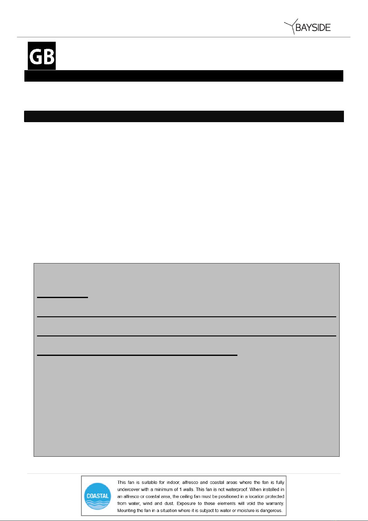
6. The structure to which the fan is to be mounted must be capable of supporting a weight of 30kg.
7. The fan should be mounted so that the blades are at least 2.3 m above the floor in Europe or 2.1 m
above the floor in Australia.
8. This fan is suitable for indoor, alfresco and coastal areas where the fan is fully undercover with a
minimum of 1 walls. This fan is not waterproof. When installed in an alfresco or coastal area, the
ceiling fan must be positioned in a location protected from water, wind and dust. Exposure to these
elements will void the warranty. Mounting the fan in a situation where it is subject to water or moisture
is dangerous.
9. Only a licensed electrician should execute the installation.

Lagoon Fan Installation Instructions
4 | P a g e
BEFORE INSTALLATION
Unpack your ceiling fan carefully. Remove all parts and hardware. Examine all parts, you should have
the following:
Fan without light
Fan with light
1
Mounting bracket x 1
1
Mounting bracket x 1
2
Pre-assembled fan motor and canopy x 1
2
Pre-assembled fan motor and canopy x 1
3
Blades x 3
3
Blades x 3
4
Wood screw x 2
4
GX53 lamp x 1
5
Motor screws for blades x 10
5
Wood screw x 2
6
Wall switch x 1 set
6
Motor screws for blades x 10
7
Wall switch x 1 set
Fig. 1

Lagoon Fan Installation Instructions
5 | P a g e
INSTALLING THE MOUNTING BRACKET
The ceiling fan must be installed in a location so that the blades are spaced 300mm from the tip of the blade
to the nearest objects or walls.
Secure the hanging bracket to the ceiling joist or structure that is capable of carrying a load of at least 30kg,
with two long screws provided. Ensure at least 30mm of the screw is threaded into the support.
NOTE: The bracket screws provided are for use with wooden structures only. For structures other than
wood, the appropriate screw type MUST be used.
Angled ceiling Installation
This fan hanging system DOES NOT support a degree angled ceiling installation.
Fig. 2

Lagoon Fan Installation Instructions
6 | P a g e
INSTALLING THE FAN
Blade attachment (Fig.3)
Secure the blade on the motor by using 3 screws to tighten it, ensuring they are tightened simultaneously.
(Take care not to over tighten as this can damage blades)
Once completed, repeat the process on the remaining blades.
Light kit installation (For fan with light) (Fig.4)
Install the globe (included, Max. 23W, GX53) in the lamp holder.
HANGING THE FAN
Lift the fan assembly to the mounting bracket (1) and let the J-hook (2) of the mounting bracket go through
the hole of the hanging canopy (3) and hang up the fan assembly. Fig. 5
Connect the male and female connector together (4). Fig. 5
Complete the electrical wiring using the diagram below (Fig.6).
Fig. 3
Fig. 4
Fig. 5

Lagoon Fan Installation Instructions
7 | P a g e
ELECTRICAL WIRING DIAGRAM
WARNING: FOR YOUR SAFETY ALL ELECTRICAL CONNECTIONS MUST BE UNDERTAKEN BY A
LICENSED ELECTRICIAN.
NOTE: AN ADDITIONAL ALL POLE DISCONNECTION SWITCH MUST BE INCLUDED IN THE FIXED
WIRING.
NOTE: Wiring diagram includes the light kit wiring. The light wiring diagram and switch is omitted
when no light kit is used with the ceiling fan.
USE WITH WALL SWITCH WIRING DIAGRAM:
USE WITH REMOTE WIRING DIAGRAM: (REMOTE sold separately)
1/ Remote without plugs
Fig. 6
Fig. 7

Lagoon Fan Installation Instructions
8 | P a g e
2/ Remote with plugs
FINISHING THE INSTALLATION
Loosen two screws (1) from the mounting bracket (5).
Loosen two screws (2) by half thread from the mounting
bracket (5).
Lift the hanging canopy (3) of the fan assembly up to
the mounting bracket and let the L-shape slot on the
hanging canopy go through the screws (2) on the
mounting bracket. Turn the hanging canopy until it locks
in place at the end section of the L-shape slot and
secure it by tightening the two screws (1). Avoid
damaging the electrical wiring prepared previously.
Finally attach the canopy cover (4) to the mounting
bracket, secure it by pushing the hooks of the canopy
cover into the slot holes of the hanging canopy and turn
it anti clockwise.
Fig. 9
Fig. 8

Lagoon Fan Installation Instructions
9 | P a g e
USING YOUR CEILING FAN
FAN WALL CONTROL
Turn on the power and check the operation of the fan.
• OFF Position – Fan off
• 3rd Position – Low fan speed
• 2nd Position – Medium fan speed
• 1st Position – High fan speed
Light Control
• Toggle Switch – On/off
REVERSING SWITCH
Your ceiling fan can operate in either summer or winter mode.
SUMMER Mode: The reverse switch shall be in the “down” (SUMMER) position to make the fan rotate in an
anticlockwise direction. The airflow will be directed downwards, for cooling in summer.
WINTER Mode: The reverse switch shall be in the “up” (WINTER) position to make the fan rotate in a clockwise
direction. The airflow will be directed upwards assisting in the circulation of warm air, for energy conservation in
winter.
AFTER INSTALLATION
WOBBLE:
NOTE: ceiling fans tend to move during operation due to the fact that they are mounted on a rubber grommet. If the
fan was mounted rigidly to the ceiling it would cause excessive vibration. Movement of a few centimetres is quite
acceptable and DOES NOT suggest any problem.
TO REDUCE THE FAN WOBBLE: Please check that all screws which fix the mounting bracket and down rod are
secure.
NOISE:
Fig. 11
Fig. 10

Lagoon Fan Installation Instructions
10 | P a g e
When it is quiet (especially at night) you may hear occasional small noises. Slight power fluctuations and frequency
signals superimposed in the electricity for off-peak hot water control, may cause a change in fan motor noise. This
is normal. Please allow a 24-hour “settling-in” period, most noises associated with a new fan disappear during this
time.
The manufacturer’s warranty covers actual faults that may develop and NOT minor complaints such as hearing the
motor run –All electric motors are audible to some extent.
CARE AND CLEANING:
Periodic cleaning of your ceiling fan is the only maintenance required. Use a soft brush or lint free cloth to avoid
scratching the paint finish. Please turn off electricity power when you do so.
Do not immerse your ceiling fan in the water. It could damage the motor or the blades and create the possibility
of an electrical shock.
Ensure that the fitting does not come in contact with any organic solvents or cleaners.
To clean the fan blade, wipe with only a damp clean cloth with NO organic solvents or cleaners.
The motor has a permanently lubricated ball bearing so there is no need to oil.
NOTE: Always turn OFF the power at the mains switch before attempting to clean your fan.
TECHNICAL INFORMATION
Fan models
Rated Voltage
Rated power (motor)
Rated power lamp
52”blade fan only
220-240 VAC
55 W
N/A
52”blade fan with light
220-240 VAC
55 W
Max. 23 W, GX53
WARRANTY INFORMATION
IN AUSTRALIA / NEW ZEALAND –Please refer to the separated WARRANTY STATEMENT.
IN EUROPE –If you are a European customer please contact the retail outlet where the fan was
purchased for warranty service.

Lagoon Fan Installation Instructions
11 | P a g e
WIR GRATULIEREN ZUM KAUF DIESES PRODUKTES
Wir gratulieren zum Kauf dieses Qualitätsproduktes von Bayside. Bitte lesen Sie die Sicherheitshinweise vollständig
und sorgfältig durch, um den ordnungsgemäßen und sicheren Einsatz des Gerätes zu gewährleisten.
SICHERHEITSMASSREGELN
Die nachfolgenden Informationen auf dieser Seite dienen dazu einen störungsfreien und vor allem
sicheren Betrieb Ihres neuen Deckenventilators sicher zu stellen.
1. Europa: Dieses Gerät darf von Kindern im Alter von 8 Jahren und älter und von Personen mit
verminderten körperlichen, sensorischen oder geistigen Fähigkeiten, oder Personen, die keine
Erfahrung mit dem Einsatz des Gerätes haben, betrieben werden, vorausgesetzt diese werden dabei
überwacht, oder diese wurden ordnungsgemäßüber den sicheren Einsatz des Gerätes unterrichten
und verstehen die Gefahren, die mit dem Betrieb des Gerätes verbunden sind. Reinigungs- und
Wartungsarbeiten dürfen nicht von Kindern ohne die Aufsicht eines Erwachsenen ausgeführt werden.
2. Kinder müssen in der Umgebung dieses Geräts stets beaufsichtigt werden, um sicherzustellen dass
diese nicht mit dem Gerät spielen.
3. Ein allpoliger Trennschalter muss in der Kabelfestinstallation gemäß den örtlich geltenden
Vorschriften für elektrische Installationen integriert werden.
4. Entsorgen Sie elektrische Geräte niemals im regulären Hausmüll, sondern geben Sie das Gerät
stets ordnungsgemäßbei einer Sammelstelle für elektronische Altgeräte ab. Bitte treten Sie mit Ihrer
örtlichen Verwaltung in Kontakt für ausführliche Informationen bezüglich der Adressen der örtlichen
Sammelstellen. Wenn elektronische Geräte in Mülldeponien oder Landaufschüttungen entsorgt
werden, können gefährliche Substanzen in das Grundwasser und somit in den Lebensmittelkreislauf
geraten und die Gesundheit gefährden, oder gar Gesundheitsschäden verursachen.
5. Die tragende Struktur an der der Ventilator befestigt wird, muss mindestens ein Gewicht von 30kg
tragen können.
6. In Europa sollte der Ventilator so an der Decke befestigt werden, dass sich die Ventilatorflügel
mindestens 2,3m über dem Boden befinden, und in Australien sollten sich die Ventilatorflügel
mindestens ca. 2,1m über dem Boden befinden.
7. Dieser Ventilator ist nur für den Einsatz in geschlossenen Räumen geschaffen. Durch die Installation
an Orten wo der Ventilator Wasser oder Feuchtigkeit ausgesetzt würde, setzen Sie sich möglichen
Personenverletzungen oder anderen Gefahren aus, und die Garantie für das Gerät erlischt.
8. Die Installation des Gerätes sollte nur von einem qualifizierten und zugelassenen Elektriker
ausgeführt werden.

Lagoon Fan Installation Instructions
12 | P a g e
VOR DER INSTALLATION ZU BEACHTEN
Packen Sie Ihren Deckenventilator vorsichtig aus. Entfernen Sie alle Teile und Beschläge. Überprüfen
Sie alle Teile. Sie sollten Folgendes haben:
Ventilator ohne Lampe
Ventilator mit Lampe
1
Montagewinkel x 1
1
Montagewinkel x 1
2
Vormontierter Ventilatormotor und -gehäuse x 1
2
Vormontierter Ventilatormotor und -gehäuse x
1
3
Ventilatorflügel x 3
3
Ventilatorflügel x 3
4
Schraube für Montagewinkel x 2
4
GX53 x 1
5
Motorschrauben für Ventilatorflügel x 10
5
Schraube für Montagewinkel x 2
6
Fernbedienung 1 Satz
6
Motorschrauben für Ventilatorflügel x 10
7
Fernbedienung 1 Satz
Fig. 1

Lagoon Fan Installation Instructions
13 | P a g e
INSTALLATION DER DECKENHAL TERUNG
Der Deckenventilator muss an einem Ort installiert werden, wo die Flügelspitzen mindestens einen
Abstand von 30cm zum nächsten Gegenstand oder der Wand haben
Befestigen Sie die Halterung an einem sicheren Deckenträger oder einer strukturell äquivalenten
Stelle, die ein Gewicht von mindestens 30KG tragen kann, und verwenden Sie dazu die zwei
mitgelieferten Schrauben. Stellen Sie sicher, dass die Schraubengewinde mindestens 30mm in den
Untergrund eingedreht werden.
HINWEIS: Die für die Halterung mitgelieferten Schrauben sind nur für den Einsatz mit
Holzstrukturen geeignet. Für andere Materialien MÜSSEN entsprechend geeignete
Schraubentypen verwendet werden.
Installation an geneigten Decken
Dieses Ventilator-Aufhängesystem unterstützt NICHT die Installation des Ventilators an einer Schräge.
Abb. 2
DECKENTRÄGER MUSS
EINE TRAGFÄHIGKEIT
VON BIS ZU 30 KG
AUFWEISEN.

Lagoon Fan Installation Instructions
14 | P a g e
INSTALLATION DER VENTILATORFLÜGEL
Befestigung der Ventilatorflügel (Abb. 3)
Fixieren Sie den Ventilatorflügel mithilfe von 3 Schrauben am Motor. Achten Sie darauf, beide Schrauben
gleichzeitig festzuziehen. (Überziehen Sie die Schrauben nicht, da dies die Ventilatorflügel beschädigen
könnte.)
Wenn Sie den Ventilatorflügel angebracht haben, wiederholen Sie den Vorgang mit den restlichen
Ventilatorflügeln.
Installation des Beleuchtungssets (für Ventilatoren mit Beleuchtung) (Abb. 4)
Installieren Sie die Glühlampe (max. 23W, GX53) in der Lampenfassung.
AUFHÄNGEN DES VENTILATORS
Heben Sie die Ventilatoreinheit an die Deckenhalterung (1), sodass der J-Haken der Deckenhalterung durch
das Loch der Abdeckung des Aufhängesystems (3) geführt wird und hängen Sie die Ventilatoreinheit ein.
Abb. 5
Verbinden Sie Stecker und Buchse (4). Abb. 5
Beenden Sie die elektrische Verdrahtung wie im nachfolgenden Schaltdiagramm gezeigt (Abb. 6).
Abb. 3
Abb. 4
Abb. 5

Lagoon Fan Installation Instructions
15 | P a g e
ELEKTRISCHES SCHALTDIAGRAMM
WARNHINWEIS: IM INTERESSE IHRER PERSÖNLICHEN SICHERHEIT MÜSSEN ALLE
ELEKTRISCHEN ANSCHLÜSSE VON EINEM ZUGELASSENEN ELEKTRIKER AUSGEFÜHRT
WERDEN.
HINWEIS: EIN ZUSÄTZLICHER, ALLPOLIGER TRENNSCHATER MUSS IN DER INSTALLATION DER
WANDVERKABELUNG ENTHALTEN SEIN.
DER EINSATZ MIT FEST INSTALLIERTEM WANDSCHALTER - SCHALTDIAGRAMM:
DER EINSATZ MIT FERNBEDIENUNG - SCHALTDIAGRAMM: (FERNBEDIENUNG ist getrennt
erhältlich)
1/ Fernbedienung ohne Stecker
Abb. 6
Abb. 7

Lagoon Fan Installation Instructions
16 | P a g e
To motor L
Zum Motor L
For light
Für die Leuchte
To motor N
Zum Motor N
2/ Fernbedienung mit Stecker
FINISHING THE INSTALLATION
Lösen Sie die zwei Schrauben (1) in der Deckenhalterung (5).
Lösen Sie die Schrauben (2), bis etwa die Hälfte des Gewindes
sichtbar ist, aus der Deckenhalterung (5).
Schieben Sie die Abdeckung des Aufhängesystems (3) der
Ventilatoreinheit bis zur Deckenhalterung hoch und führen Sie
die Schrauben (2) an der Deckenhalterung durch die L-förmige
Nut an der Abdeckung des Aufhängesystems. Drehen Sie die
Abdeckung des Aufhängesystems, bis sie im Endabschnitt der
L-förmigen Nut einrastet, und fixieren Sie sie durch Festziehen
der zwei Schrauben (1). Vorsichtig vorgehen, damit die zuvor
angeschlossenen Elektrokabel nicht beschädigt werden.
Befestigen Sie zum Schluss das Ventilatorgehäuse (4) an der Deckenhalterung, fixieren Sie dieses,
indem Sie die Haken an der Abdeckung in die Langlöcher der Abdeckung schieben und sie gegen
den Uhrzeigersinn drehen.
Abb. 9
Abb. 8

Lagoon Fan Installation Instructions
17 | P a g e
DER BETRIEB DES DECKENVENTILATORS
VENTILATOR WANDSTEUERUNG
Schalten Sie die Stromversorgung ein, und überprüfen Sie die
Funktion des Ventilators.
• AUS-Stellung –Ventilator ist ausgeschaltet
• 3. Einstellposition – niedrige Ventilatorgeschwindigkeit
• 2. Einstellposition – mittlere Ventilatorgeschwindigkeit
• 1. Einrastposition –hohe Ventilatorgeschwindigkeit
Lichtsteuerung
• Kippschalter – Ein/Aus
RÜCKLAUFFUNKTION
Der Ventilator kann sowohl im Vorlauf als auch im Rücklauf betrieben werden.
SOMMERBETRIEB: Wenn der Schalter für die Rücklauffunktion auf “down” (SOMMER) steht, dreht der
Ventilator sich gegen den Uhrzeigersinn. Die Luftbewegung wird nach unten gelenkt und bringt im
Sommer den gewünschten Abkühlungseffekt.
WINTERBETRIEB: Wenn der Schalter für die Rücklauffunktion auf “up” (WINTER) steht, dreht sich der
Ventilator im Uhrzeigersinn. Die Luftbewegung wird nach oben gelenkt, um im Winter Energie zu sparen.
Reverse Switch
Umkehrschalter
Winter
Winter
Summer
Sommer
Down Draft
Abwind
Updraft
Aufwind
Counter clockwise Rotation
Linksdrehung
Clockwise Rotation
Rechtsdrehung
Abb. 11
Sommer
Abwind
Aufwind
Linksdrehung
Rechtsdrehung
Abb. 10
LEUCHTE

Lagoon Fan Installation Instructions
18 | P a g e
NACH DER INSTALLATION
AUSSCHWENKEN
Bitte beachten Sie: Da der Deckenventilator auf einer Gummitülle befestigt ist, kann es während des Betriebs zu
Ausschwenkungen kommen. Wäre der Ventilator jedoch zu fest an der Decke angebracht, würde es zu
übermäßigen Vibrationen führen. Das Ausschwenken des Ventilators umwenige Zentimeter stellt kein Problem dar.
VERRINGERUNG DES AUSSCHWENKENS: Bitte stellen Sie sicher, dass alle die Halterung und die Panelstange
fixierenden Schrauben festgezogen sind.
GERÄUSCHE
Sie können gelegentlich Geräusche wahrnehmen, sobald es in Ihrer Umgebung ruhig ist (besonders nachts).
Geringfügige Leistungsschwankungen im Stromnetz sowie den Strom überlagernde Frequenzsignale zur
Warmwassersteuerung außerhalb der Stoßzeiten können die Geräusche des Ventilatormotors beeinflussen.
Dies ist normal. Bitte kalkulieren Sie eine 24-stündige Anpassungsphase ein, während der die meisten auf den
Ventilator zurückzuführenden Geräusche verschwinden.
Die Gewährleistung des Originalherstellers deckt tatsächliche auftretende Fehler ab und KEINE unwesentlichen
Beanstandungen wie z. B. Motorengeräusche. Alle elektronischen Motoren sind bis zu einem gewissen Grad hörbar.
REINIGUNG UND PFLEGE
Die einzige erforderliche Wartung ist die regelmäßige Reinigung Ihres Ventilators. Verwenden Sie dafür eine
weiche Bürste oder einen fusselfreien Lappen, um ein Verkratzen der Lackierung zu vermeiden.
Tauchen Sie Ihren Deckenventilator nicht in Wasser. Dadurch könnte der Motor oder die Flügel beschädigt
werden und die Gefahr eines Stromschlags entstehen.
Achten Sie darauf, dass die Installation nicht mit organischen Lösungsmitteln oder Reinigungsmitteln in
Kontakt kommt.
Wischen Sie das Ventilatorblatt nur mit einem feuchten, sauberen Tuch OHNE organische Lösungsmittel
oder Reinigungsmittel ab.
Der Motor ist mit einem dauergeschmierten Kugellager ausgestattet und muss daher nicht geölt werden.
BITTE BEACHTEN SIE: Schalten Sie vor der Reinigung des Ventilators den Strom über den Netzschalter ab.
TECHNISCHE DATEN
VENTILATOR-Modelle
Nennspannung
Nennleistung (Motor)
Batterie für
Fernbedienung
Nur 132 cm Flügelventilator
220-240 V AC
55 W
Nicht zutreffend
132 cm Flügelventilator mit
Beleuchtung
220-240 V AC
55 W
Max. 22 W, GX53

Lagoon Fan Installation Instructions
19 | P a g e
GARANTIE-HINWEISE
KUNDEN IN AUSTRALIEN / NEU SEELAND –Bitte beachten Sie die separate
GARANTIEERKLÄRUNG.
KUNDEN IN EUROPA –Falls Sie ein Kunde in Europa sind, dann treten Sie für Garantieleistungen bitte
mit dem Fachgeschäft in Kontakt, wo Sie das Gerät gekauft haben.
Other manuals for LAGOON
2
Table of contents
Languages:
Other Bayside Fan manuals

Bayside
Bayside LAGOON CTC Installation guide

Bayside
Bayside LAGOON User manual

Bayside
Bayside CALYPSO Installation guide

Bayside
Bayside NAUTILUS Installation guide

Bayside
Bayside CALYPSO Installation guide

Bayside
Bayside NAUTILUS Owner's manual

Bayside
Bayside MEGARA User manual

Bayside
Bayside LAGOON User manual