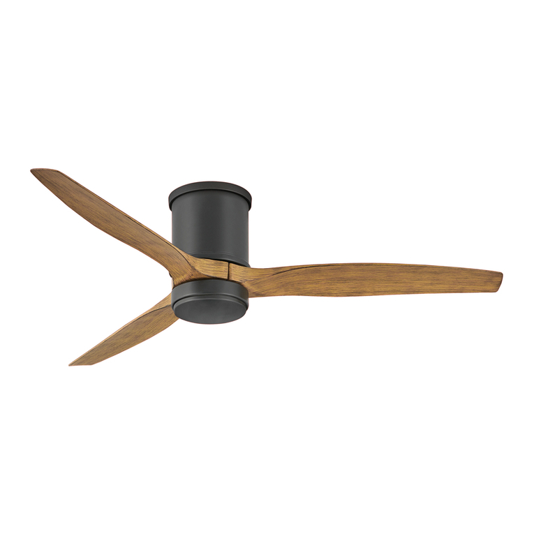
Bayside LAGOON User manual

V1.1-EU (10/ 2020)
BAYSIDE
LAGOON
CEILING FAN
⚫INSTALLATION
⚫OPERATION
⚫MAINTENANCE
⚫WARRANTY INFORMATION
CAUTION
READ INSTRUCTIONS CAREFULLY FOR SAFE
INSTALLATION AND FAN OPERATION.

Lagoon Fan Installation Instructions
1 | P a g e
V1.1-EU (10/2020)
CONTENTS
GB
Installation instruction manual ........................................................................................... 2
D
Installationsanleitung ........................................................................................................ 11
F
Guide d’installation............................................................................................................ 22
E
Manual de instrucciones de instalación............................................................................. 33
I
Manuale delle istruzioni di installazione............................................................................ 44
NL
Installatiehandleiding.........................................................................................................53
EL
Εγχειρίδιο οδηγιών εγκατάστασης ....................................................................................63
Contact:
Beacon International Ltd
Hong Kong Head Office: Room 05, 18/F, Kimberland Center, 55 Wing Hong Street, Cheung Sha Wan Kowloon, Hong Kong
Tel +852 34915904 Fax +852 34915917
China showroom /Office: 11/Fl,Guzhen Lighting Building B, Mid Zhongxing Road,Guzhen, Zhongshan, GuangDong, China.
Tel: +86 760 8986 6388 Fax: +86 760 8986 6380
info@beaconinternational.com
www.beaconinternational.com
Beacon Lighting Europe GmbH
Campus Fichtenhain 42, 47807 Krefeld, Germany
TEL +49 (2151) 325 82 39 FAX +49 (2151) 325 70 65
sales@beaconlighting.eu
www.beaconlighting.eu

Lagoon Fan Installation Instructions
2 | P a g e
V1.1-EU (10/2020)
THANK YOU FOR PURCHASING
Thank you for purchasing this quality Bayside product. To ensure correct function and safety, please read
and save all instructions before using the product.
SAFETY PRECAUTIONS
1. This appliance can be used by children aged from 8 years and above and persons with reduced
physical, sensory or mental capabilities or lack of experience and knowledge if they have been given
supervision or instruction concerning the use of the appliance in a safe way and understand the
hazards involved. Cleaning and maintenance shall not be undertaken by children without supervision.
2. Children should be supervised to ensure that they do not play with the appliance.
3. An all-pole disconnection switch must be incorporated into the fixed wiring, in accordance with local
wiring rules.
4. Do not dispose of electrical appliances as unsorted municipal waste, use separate collection
facilities. Contact your local government for information regarding the collection systems available. If
electrical appliances are disposed of in landfills or dumps, hazardous substances can leak into the
ground water and get into the food chain, damaging your health and well-being.
5. The structure to which the fan is to be mounted must be capable of supporting a weight of 30kg.
6. The fan should be mounted so that the blades are at least 2.3 m above the floor .
7. This fan is suitable for indoor, alfresco and coastal areas where the fan is fully undercover with a
minimum of 1 walls. This fan is not waterproof. When installed in an alfresco or coastal area, the
ceiling fan must be positioned in a location protected from water, wind and dust. Exposure to these
elements will void the warranty. Mounting the fan in a situation where it is subject to water or moisture
is dangerous.
8. Only a licensed electrician should execute the installation.
9. WARNING: If unusual wobbling or oscillating movement is observed, immediately stop using the
ceiling fan and contact the manufacturer, its service agent or suitably qualified persons.
10. The replacement of parts of the safety suspension system device shall be performed by the
manufacturer, its service agent or suitably qualified persons.
11.The fixing means for attachment to the ceiling such as hooks or other devices shall be fixed with a
sufficient strength to withstand 4 times the weight of the ceiling fan; that the mounting of the
suspension system shall be performed by the manufacturer, its service agent or suitably qualified
persons.
12. caution, risk of electric shock

Lagoon Fan Installation Instructions
3 | P a g e
V1.1-EU (10/2020)
BEFORE INSTALLATION
Unpack your ceiling fan carefully. Remove all parts and hardware. Examine all parts, you should have
the following:
Fig. 1
Fan without light Fan with light
1 Mounting bracket x 1 1 Mounting bracket x 1
2 Pre-assembled fan motor and canopy x 1 2 Pre-assembled fan motor and canopy x 1
3 Blades x 3 3 Blades x 3
4 Mounting screw x 4 4 GX53 lamp x 1
5 Motor screws for blades x 10 5 Mounting screw x 4
6 Remote and receiver x 1 set 6 Motor screws for blades x 10
7. remote and receiver x 1 set

Lagoon Fan Installation Instructions
4 | P a g e
V1.1-EU (10/2020)
INSTALLING THE MOUNTING BRACKET
•The ceiling fan must be installed in a location so that the blades are spaced 300mm from the tip of
the blade to the nearest objects or walls.
•Secure the hanging bracket to the ceiling joist or structure that is capable of carrying a load of at
least 22kg, with two long screws provided. Ensure at least 30mm of the screw is threaded into the
support.
•with the 4 long screws provided. Ensure at least 30mm of the screw is threaded into the support.
(Fig. 2)
NOTE: The bracket screws provided are for use with wooden structures only. For structures other
than wood, the appropriate screw type MUST be used. Ensure the screws used are suitable for
the mounting surface and the surrounding environment.
Angled ceiling Installation
This fan hanging system DOES NOT support a degree angled ceiling installation.
Fig. 2
Fig. 2
22 KG

Lagoon Fan Installation Instructions
5 | P a g e
V1.1-EU (10/2020)
INSTALLING THE FAN
Blade attachment (Fig.3)
Secure the blade on the motor by using 3 screws to tighten it, ensuring they are tightened simultaneously.
(Take care not to over tighten as this can damage blades)
Once completed, repeat the process on the remaining blades.
Light kit installation (For fan with light) (Fig.4)
Install the globe (included, Max. 18 W, GX53) in the lamp holder.
HANGING THE FAN
•Lift the fan assembly to the mounting bracket (1) and let the J-hook (2) of the
mounting bracket go through the hole of the hanging canopy (3) and hang up
the fan assembly. Fig. 5
•Connect the male and female connector together (4). Fig. 5
Fig. 5
Fig.
3
Fig.
4

Lagoon Fan Installation Instructions
6 | P a g e
V1.1-EU (10/2020)
Complete the electrical wiring using the diagram below (Fig.6).
•Complete the electrical wiring according to the ‘ELECTRICAL WIRING DIAGRAM’ section below.
PREPARE AND COMPLETE THE ELECTRICAL WIRING --- WIRING DIAGRAM (FIG. 6)
WARNING: FOR YOUR SAFETY ALL ELECTRICAL CONNECTIONS MUST BE UNDERTAKEN BY A
LICENSED ELECTRICIAN.
NOTE: AN ADDITIONAL ALL POLE DISCONNECTION SWITCH MUST BE INCLUDED IN THE FIXED
WIRING.
Fig. 6
From mains supply to mounting bracket terminal block: (Fig. 6)
1. Connect the live supply wire to the “L” terminal of the terminal block on the mounting bracket.
2. Connect the neutral supply wire to “N” terminal of the terminal block on the mounting bracket.
3. Connect earth wire to the earth terminal of the terminal block on the mounting bracket.
From mounting bracket to receiver and motor: (Fig. 6)
4. Connect the supply wiring connector from the mounting bracket to the input of the remote receiver.
5. Connect the output wires connector of remote receiver to the input wires connectors of the fan motor
and the light kit.

Lagoon Fan Installation Instructions
7 | P a g e
V1.1-EU (10/2020)
FINISHING THE INSTALLATION
•Loosen two screws (1) from the mounting bracket (5).
•Loosen two screws (2) by half thread from the mounting
bracket (5).
•Lift the hanging canopy (3) of the fan assembly up to
the mounting bracket and let the L-shape slot on the
hanging canopy go through the screws (2) on the
mounting bracket. Turn the hanging canopy until it locks
in place at the end section of the L-shape slot and
secure it by tightening the two screws (1). Avoid
damaging the electrical wiring prepared previously.
•Finally attach the canopy cover (4) to the mounting bracket, secure it by pushing the hooks
of the canopy cover into the slot holes of the hanging canopy and turn it anti clockwise.
USING YOUR CEILING FAN
REMOTE CONTROL
Your ceiling fan is controlled via the remote control. There are 4 buttons (HI, MED, LOW, OFF) to control
the fan speed and one button to control light on/off. Fig. 10
Before operating the remote, the following must be considered.
-2 x AAA 1.5V (size) batteries are required to operate the remote control. Remove the battery cover
from the back of the remote and insert 2 x AAA batteries. Ensure the polarities are correct as
shown in the battery compartment. Fig. 8 (Batteries included.)
-The remote (transmitter) and receiver must be configured so that communication between each
other is paired up. This is achieved by setting the DIP switch on the receiver and remote on the
same setting. Fig. 9
Note: The DIP switch assembly has 4 switches which can be setup to 16 different transmitting
code combinations. This is practical when there is more than 1 remote/receiver pair operating
locally or in the same room.
Note: To access the receiver DIP switches, remove the DIP switch cover.
Fig. 8 Remote battery compartment Fig. 9 Receiver DIP switch
Fig. 7

Lagoon Fan Installation Instructions
8 | P a g e
V1.1-EU (10/2020)
OPERATING THE REMOTE:
Before you start using the remote, take the time to read through this section and get familiar with the
buttons and function of each button.
LED Indicator
The red LED indicator on the top of the transmitter will flash
when the buttons are active.
BUTTONS ON THE REMOTE
HI: Press the button to set fan running at High speed.
MED: Press the button to set fan running at Medium speed.
LOW: Press the button to set fan running at Low speed.
OFF: Press the button to turn OFF the fan.
: Press the button to turn ON/ OFF the light.
The LED light has a 3-step dimmable function which is
controlled by an ON/OFF switch.
When the LED light is ON and at 100% brightness, press the
light button “ON and then OFF within 5 seconds”, to dim the
LED light. Repeat pressing ON and then OFF within 5 seconds to dim further in the following sequence:
100% brightness → 40% brightness → 15% brightness → 100% brightness.
To switch back to 100% brightness at any stage, turn OFF the luminaire, and then wait after 5
seconds turn ON the luminaire, it will reset to 100% brightness.
The remote has memory function. If the fan or light is turned off by the isolating switch, it will memorise
and recover the last status when turned on next.
Fig. 10

Lagoon Fan Installation Instructions
9 | P a g e
V1.1-EU (10/2020)
INSTALLATION OF THE REMOTE CONTROL HOLDER (Fig. 11)
REVERSING SWITCH
Your ceiling fan can operate in either summer or winter mode.
SUMMER Mode: The reverse switch shall be in the “down” (SUMMER) position to make the fan rotate in an
anticlockwise direction. The airflow will be directed downwards, for cooling in summer.
WINTER Mode: The reverse switch shall be in the “up” (WINTER) position to make the fan rotate in a clockwise
direction. The airflow will be directed upwards assisting in the circulation of warm air, for energy conservation in
winter.
Fig. 12
Fig. 11a
Fig. 11b
1. Locate a suitable wall or surface to
fix the remote control wall holder.
2. Remove the screw cover and install
the holder using the 2 screws and
re-install the screw cover. (Fig.11a).
3. Slide the remote into the holder.
(Fig. 11b).

Lagoon Fan Installation Instructions
10 | P a g e
V1.1-EU (10/2020)
AFTER INSTALLATION
WOBBLE:
NOTE: ceiling fans tend to move during operation due to the fact that they aremounted on a rubber grommet. If the
fan was mounted rigidly to the ceiling it would cause excessive vibration. Movement of a few centimetres is quite
acceptable and DOES NOT suggest any problem.
TO REDUCE THE FAN WOBBLE: Please check that all screws which fix the mounting bracket and down rod are
secure.
BALANCING KIT: A balancing kit is provided to balance the ceiling fan on initial installation. Please refer to the
instruction on how to use the balancing kit. The balancing kit can be used to assist re-balancing should the ceiling
fan become un-balanced again. Store your balancing kit away after installation for future use if required.
NOISE:
When it is quiet (especially at night) you may hear occasional small noises. Slight power fluctuations and frequency
signals superimposed in the electricity for off-peak hot water control, may cause a change in fan motor noise. This
is normal. Please allow a 24-hour “settling-in” period, most noises associated with a new fan disappear during this
time.
The manufacturer’s warranty covers actual faults that may develop and NOT minor complaints such as hearing the
motor run –All electric motors are audible to some extent.
CARE AND CLEANING:
•Periodic cleaning of your ceiling fan is the only maintenance required. Use a soft brush or lint free cloth to avoid
scratching the paint finish. Please turn off electricity power when you do so.
•Do not immerse your ceiling fan in the water. It could damage themotor or the blades and create the possibility
of an electrical shock.
•Ensure that the fitting does not come in contact with any organic solvents or cleaners.
•To clean the fan blade, wipe with only a damp clean cloth with NO organic solvents or cleaners.
•The motor has a permanently lubricated ball bearing so there is no need to oil.
NOTE: Always turn OFF the power at the mains switch before attempting to clean your fan.
TECHNICAL INFORMATION
Fan models
Rated Voltage
Rated power (motor)
Rated power lamp
Lagoon CTC/
SKU#213034;213035
220-240 V~
55 W
N/A
Lagoon CTC/
SKU#213036;213037
220-240 V~
55 W
GX53,18W, 1700lm,
3000K, 3 step-dim
WARRANTY INFORMATION
IN EUROPE – If you are a European customer please contact the retail outlet where the fan was
purchased for warranty service.

Lagoon Fan Installation Instructions
11 | P a g e
V1.1-EU (10/2020)
VIELEN DANK FÜR IHREN KAUF
Vielen Dank, dass Sie sich für dieses Qualitätsprodukt von Bayside entschieden haben. Um eine korrekte
Funktion und Sicherheit zu gewährleisten, lesen und bewahren Sie bitte alle Anweisungen auf, bevor Sie
das Produkt verwenden.
SICHERHEITSVORKEHRUNGEN
1. Dieses Gerät kann von Kindern ab 8 Jahren sowie Personen mit eingeschränkten physischen,
sensorischen oder geistigen Fähigkeiten oder Mangel an Erfahrung und Wissen im Umgang mit dem
Gerät verwendet werden, wenn sie beaufsichtigt oder bezüglich des sicheren Gebrauchs
unterwiesen wurden und die daraus resultierenden Gefahren verstanden haben. Die Reinigung und
Wartung dürfen nicht durch Kinder ohne Aufsicht erfolgen.
2. Kinder müssen beaufsichtigt werden, um sicherzustellen, dass sie nicht mit dem Gerät spielen.
3. In die feste Verkabelung muss ein allpoliger Trennschalter gemäß den örtlichen
Verkabelungsvorschriften eingebaut werden.
4. Entsorgen Sie elektrische Geräte nicht als unsortierten Siedlungsabfall, nutzen Sie separate
Sammelstellen. Wenden Sie sich an Ihre Gemeindeverwaltung, um Informationen über die
verfügbaren Sammelsysteme zu erhalten. Wenn Elektrogeräte auf Deponien entsorgt werden,
können gefährliche Stoffe in das Grundwasser eindringen und in die Nahrungskette gelangen, was
Ihrer Gesundheit und Ihrem Wohlbefinden schadet.
5. Die Struktur, an der der Ventilator montiert werden soll, muss ein Gewicht von 30 kg tragen können.
6. Der Ventilator sollte so montiert werden, dass sich die Flügel mindestens 2,3 m über dem Boden
befinden.
7. Dieser Ventilator ist für Innenbereiche, im Freien und Küstenregionen geeignet, sofern er geschützt
– vollständig von einem Dach bedeckt und durch mindestens einer Wand geschützt – betrieben wird.
Dieser Ventilator ist nicht wasserfest. Im Freien oder in einer Küstenregion muss der
Deckenventilator an einem Ort installiert werden, der vor Wasser, Wind und Staub geschützt ist.
Andernfalls erlischt die Garantie. Es ist gefährlich, den Ventilator an einem Ort zu installieren, an
dem er weder vor Wasser noch Feuchtigkeit geschützt ist.
8. Nur ein qualifizierter Elektriker darf die Installation durchführen.
9. WARNUNG: Bei ungewöhnlichen Unwucht- oder oszillierenden Bewegungen ist der
Deckenventilator sofort außer Betrieb zu nehmen und der Hersteller, sein Servicepartner oder
entsprechend qualifizierte Personen zu kontaktieren.
10. Der Austausch von Teilen der Sicherheitsaufhängung ist vom Hersteller, seinem Servicepartner oder
entsprechend qualifizierten Personen durchzuführen.
11. Die Befestigungsmittel zur Befestigung an der Decke, wie z. B. Haken oder andere Vorrichtungen,

Lagoon Fan Installation Instructions
12 | P a g e
V1.1-EU (10/2020)
sind mit einer ausreichenden Festigkeit zu befestigen, um dem 4-fachen Gewicht des
Deckenventilators standzuhalten; die Montage des Aufhängungssystems muss vom Hersteller,
seinem Servicepartner oder entsprechend qualifizierten Personen durchgeführt werden.
12. Vorsicht, Stromschlaggefahr

Lagoon Fan Installation Instructions
13 | P a g e
V1.1-EU (10/2020)
VOR DER MONTAGE
Packen Sie Ihren Deckenventilator vorsichtig aus. Entfernen Sie alle Teile und Beschläge. Überprüfen
Sie alle Teile. Sie sollten Folgendes haben:
Abb. 1
Ventilator ohne Licht Ventilator mit Licht
1. 1 x Halterung
1. 1 Montagehalterung
2. 1 Vormontierter Ventilatormotor und
Baldachin
2. 1 Vormontierter Ventilatormotor und
Baldachin
3. 3 Flügel
3. 3 Flügel
4. 4 Montageschrauben
4. 1 GX53-Lampe
5. 10 Motorschrauben für Ventilatorflügel
5. 4 Befestigungsschrauben
6. 1 Satz Fernbedienung und Empfänger
6. 10 Motorschrauben für Ventilatorflügel
7. 1 Fernbedienung und Empfänger

Lagoon Fan Installation Instructions
14 | P a g e
V1.1-EU (10/2020)
MONTAGE DER HALTERUNG
•Der Deckenventilator muss mit einem Abstand von 300 mm von der Flügelspitze bis zum nächsten
Objekt oder den Wänden installiert werden.
•Fixieren Sie mithilfe der zwei mitgelieferten langen Schrauben die Halterung mit dem Baldachin an
einem Deckenbalken oder einem Deckenträger, der mindestens eine Last von 22 kg tragen kann.
Stellen Sie sicher, dass mindestens 30 mm der Schraube in die Halterung eingeschraubt sind.
• mit den 4 mitgelieferten langen Schrauben. Stellen Sie sicher, dass mindestens 30 mm der
Schraube in die Halterung eingeschraubt sind. (Abb. 2)
HINWEIS: Die mitgelieferten Befestigungsschrauben sind nur für Holzkonstruktionen geeignet.
Für andere Konstruktionen als Holz MUSS der entsprechende Schraubentyp verwendet werden.
Stellen Sie sicher, dass die verwendeten Schrauben für die Montagefläche und die Umgebung
geeignet sind.
Installation an einer Dachschräge
Dieses Ventilator-Aufhängungssystem unterstützt NICHT die Montage des Ventilators an einer schrägen
Decke.
Abb. 2
22 kg
DECKENTRÄGER MUSS EINE
TRAGFÄHIGKEIT VON BIS ZU 22
KG AUFWEISEN.

Lagoon Fan Installation Instructions
15 | P a g e
V1.1-EU (10/2020)
MONTAGE DES VENTILATORS
Anbringen des Ventilatorflügels (Abb. 3)
Fixieren Sie den Ventilatorflügel mithilfe von drei Schrauben am Motor. Achten Sie darauf, beide
Schrauben gleichzeitig festzuziehen. (Achten Sie darauf, die Schrauben nicht übermäßig fest anzuziehen,
da die Ventilatorflügel sonst beschädigt werden könnten.)
Diesen Schritt bei den übrigen Flügeln wiederholen.
Installation des Beleuchtungssets (für Ventilatoren mit Beleuchtung) (Abb. 4)
Installieren Sie den Leuchtkörper (im Lieferumfang enthalten, max. 18 W, GX53) in der Lampenfassung.
AUFHÄNGEN DES VENTILATORS
•Heben Sie den Deckenbaldachin des Ventilators an die Montagehalterung
(1) und führen Sie den J-förmigen Haken (2) der Montagehalterung durch das
Loch des Baldachins (3) und hängen Sie die Ventilatorbaugruppe an. Abb. 5
•Stecken Sie den Stecker in die Buchse (4). Abb. 5
Abb. 5
Abb.
3
Abb.
4

Lagoon Fan Installation Instructions
16 | P a g e
V1.1-EU (10/2020)
Stellen Sie die elektrische Verkabelung anhand des folgenden Schemas
(Abb.6) fertig.
•Schließen Sie die elektrische Verdrahtung gemäß dem „BLOCKSCHALTBILD“ im nachfolgenden
Abschnitt ab.
VORBEREITUNG UND FERTIGSTELLUNG DER ELEKTRISCHEN VERKABELUNG ---
VERKABELUNGSDIAGRAMM (Abb.) 6)
WARNUNG: ZUR EIGENEN SICHERHEIT SOLLTEN ALLE ELEKTRISCHEN ANSCHLÜSSE VON
EINEM GEPRÜFTEN ELEKTRIKER VORGENOMMEN WERDEN.
HINWEIS: IN DER FESTVERDRAHTUNG SOLLTE EIN ZUSÄTZLICHER TRENNSCHALTER FÜR
ALLE PHASEN VORGESEHEN WERDEN.
Abb. 6
Von der Netzversorgung zur Klemmleiste an der Montagehalterung: (Abb. 6)
1. Verbinden Sie den Plusleiter der Stromversorgung mit der Klemme „L“ der Lüsterklemme an der
Halterung.
2. Verbinden Sie den Nullleiter der Stromversorgung mit der Klemme „N“ der Lüsterklemme an der
Halterung.
3. Verbinden Sie den Schutzleiter mit der Klemme „“ der Lüsterklemme an der Halterung.
Von der Montagehalterung zum Empfänger und Motor: (Abb. 6)
1. Verbinden Sie den Anschluss der Spannungszuleitung von der Montagehalterung mit dem Eingang
des Empfängers.
2. Verbinden Sie den Anschluss der Ausgangsleitungen des Empfängers mit den Anschlüssen der
Eingangsleitungen des Ventilatormotors und des Beleuchtungssatzes.
220-240 VAC
Stromversorgung
Von der Decke
L (Phase Ventilator)
N (Nullleiter Ventilator und Leuchte)
Erde
Braun
Blau
Gelb/Grün
Fernbedienungsempfänger

Lagoon Fan Installation Instructions
17 | P a g e
V1.1-EU (10/2020)
ABSCHLUSS DER INSTALLATION
•Lösen Sie zwei Schrauben (1) aus der Montagehalterung (5).
•Lösen Sie zwei Schrauben (2), indem Sie sie halb aus der Montagehalterung (5) drehen.
•Heben Sie den Deckenbaldachin des Ventilators an die Halterung und führen Sie den L-förmigen
Schlitz am Deckenbaldachin durch die zwei Schrauben (2) der Montagehalterung. Drehen Sie den
Baldachin bis er im Endabschnitt des L-förmigen Schlitzes einrastet und sichern Sie ihn durch
Anziehen der beiden Schrauben (1). Vorsichtig vorgehen, damit die zuvor angeschlossenen
Elektrokabel nicht beschädigt werden.
•Befestigen Sie zum Schluss die Baldachinabdeckung (4) an der Halterung. Fixieren Sie diese,
indem Sie die Haken der Baldachinabdeckung in die Schlitzöffnungen des Deckenbaldachins
schieben und sie gegen den Uhrzeigersinn drehen.
BENUTZUNG DES DECKENVENTILATORS
FERNBEDIENUNG
Ihr Deckenventilator wird über die Fernbedienung gesteuert. Auf der Fernbedienung finden Sie vier
Tasten (HI, MED, LOW, OFF) zur Steuerung der Ventilatorgeschwindigkeit und einer Taste zum Ein- und
Ausschalten der Beleuchtung. Abb. 10
Vor dem Gebrauch der Fernbedienung muss Folgendes beachtet werden.
-Es werden zwei AAA-Batterien (1,5 V) zum Betrieb der Fernbedienung benötigt. Entfernen Sie
die Batteriefachabdeckung von der Rückseite der Fernbedienung und legen Sie zwei AAA-
Batterien ein. Dabei auf die richtige Polarität achten, die im Batteriefach schematisch dargestellt
ist. (Abb. 8) (Batterien im Lieferumfang enthalten)
-Die Fernbedienung (Sender) und der Empfänger müssen konfiguriert werden, um die Verbindung
zwischen beiden Elementen herzustellen. Stellen Sie hierzu den DIP-Schalter am Empfänger und
der Fernbedienung auf die gleiche Position. Abb. 9
Hinweis: Die DIP-Schaltereinheit besitzt vier Schalter, die in 16 verschiedenen
Übertragungscode-Kombinationen gestellt werden können. Dies ist praktisch, wenn mehr als ein
Fernbedienung/Empfänger-Paar lokal oder im gleichen Zimmer benutzt wird.
Hinweis: Entfernen Sie die DIP-Schalterabdeckung, um auf die DIP-Schalter zuzugreifen.
Abb. 8 Batteriefach der Fernbedienung Abb. 9 DIP-Schalter des Empfängers
DIP-Schalter
DIP-Schalter
Beispieleinstellungen für die DIP-Schalter
Empfänger 1
Empfänger 2
DIP-Schalter auf
0110 eingestellt
DIP-Schalter auf
0111 eingestellt
DIP-Schalter auf
0110 eingestellt
DIP-Schalter auf
0111 eingestellt
Sender 1
Sender 2

Lagoon Fan Installation Instructions
18 | P a g e
V1.1-EU (10/2020)
BEDIENUNG DER FERNBEDIENUNG
Vor dem Benutzen der Fernsteuerung sollten Sie sich etwas Zeit zum Lesen dieser Anleitung nehmen
und sich mit den Tasten und deren Funktionen vertraut machen.
LED-Anzeige
Die rote LED-Anzeige auf der Spitze des Senders blinkt, wenn
die Tasten aktiviert sind.
TASTEN AUF DER FERNBEDIENUNG
HI: zum Einstellen der höchsten Geschwindigkeitsstufe
drücken.
MED: zum Einstellen der mittleren Geschwindigkeitsstufe
drücken.
LOW: zum Einstellen der niedrigsten Geschwindigkeitsstufe
drücken.
OFF: zum Ein- und Ausschalten des Ventilators drücken.
: zum Ein- und Ausschalten der Beleuchtung drücken.
Die LED-Leuchte besitzt eine 3-stufige Dimmfunktion, die durch den EIN/AUS-Schalter gesteuert
wird.
Um das LED-Licht bei einer Helligkeitsstufe von 100 % zu dimmen, drücken Sie erst den „EIN“-Schalter
und innerhalb von 5 Sekunden den „AUS“-Schalter. Wiederholtes Drücken von EIN und AUS innerhalb
von 5 Sekunden dimmt in dieser Folge: 100 % Helligkeit → 40 % Helligkeit → 15 % Helligkeit → 100 %
Helligkeit
Um von einer beliebigen Helligkeitsstufe auf 100 % zu schalten, schalten Sie die Leuchte aus,
warten 5 Sekunden und schalten sie wieder ein. Die Leuchte wird auf 100 % Helligkeit
zurückgesetzt.
Die Fernbedienung besitzt eine Speicherfunktion. Falls der Ventilator oder die Beleuchtung durch den
Trennschutzschalter ausgeschaltet wird, wird die Einstellung für das nächste Mal, wenn der Ventilator
eingeschaltet wird, gespeichert.
Abb. 10
LED-Anzeige
Ventilator mit hoher
Geschwindigkeit starten
Ventilator mit mittlerer
Geschwindigkeit starten
Ventilator mit niedriger
Geschwindigkeit starten
Ventilator ausschalten
Beleuchtung ein-/ausschalten

Lagoon Fan Installation Instructions
19 | P a g e
V1.1-EU (10/2020)
MONTAGE DER FERNBEDIENUNGSHALTERUNG (Abb. 11)
RÜCKWÄRTSLAUFSCHALTER
Ihr Deckenventilator kann im Sommer- oder Winter-Modus betrieben werden.
SOMMER-Modus: Schieben Sie den Rückwärtslauf-Schalter nach unten in die SOMMER-Position, um den
Ventilator gegen den Uhrzeigersinn zu betreiben. Der Luftstrom wird nach unten geleitet, um im Sommer zu kühlen.
WINTER-Modus: Schieben Sie den Rückwärtslauf-Schalter nach oben in die WINTER-Position, um den Ventilator
im Uhrzeigersinn zu betreiben. Der Luftstrom wird nach oben geleitet. und unterstützt so die Zirkulation warmer Luft.
Dadurch können Sie im Winter Energie sparen.
Abb. 12
Abb. 11a
Abb. 11b
1. Suchen Sie eine geeignete Wand
oder Fläche zum Anbringen der
Wandhalterung der Fernbedienung.
2. Entfernen Sie die
Schraubenabdeckung und montieren
Sie die Halterung mithilfe der zwei
Schrauben und befestigen Sie die
Schraubenabdeckung wieder. (Abb.
11a).
3. Setzen Sie die Fernbedienung in die
Halterung.
(Abb. 11b)
HI
MED
LOW
AUS
Summer
ABWIND
Drehrichtung gegen den
Uhrzeigersinn
Drehrichtung im
Uhrzeigersinn
AUFWIND
WINTER
SUMMER
Winter
Other manuals for LAGOON
2
This manual suits for next models
4
Table of contents
Languages:
Other Bayside Fan manuals
Bayside
Bayside NAUTILUS Owner's manual
Bayside
Bayside LAGOON CTC Installation guide
Bayside
Bayside LAGOON User manual

Bayside
Bayside MEGARA User manual
Bayside
Bayside NAUTILUS Installation guide
Bayside
Bayside CALYPSO Installation guide
Bayside
Bayside LAGOON User manual

Bayside
Bayside CALYPSO Installation guide
Popular Fan manuals by other brands
Clas Ohlson
Clas Ohlson FZ10-19MA instruction manual

Xpelair
Xpelair C6S Installation and maintenance instructions

Venmar
Venmar A110H65RT User's and installer's manual

Cata
Cata B-10 Use instruction

Vent-Axia
Vent-Axia HR25 Solo Installation and user instruction guide

Fanimation
Fanimation Edgewood TF300 Series owner's manual

