BBB idSWITCH EMP31 User manual

EMP31/EMP51 Master Power Unit User Manual
IDM Technologie
EMP31/EMP51
Master Power Unit
Version: A2.3
Date: December 2023

EMP31/EMP51 Master Power Unit User Manual
IDM Technologie
WARNING: HIGH VOLTAGE INSIDE
CAUTION: THE DC FUSE MUST HAVE BEENTURNED OFF BEFORE SERVICING
MADE IN CHINA

EMP31/EMP51 Master Power Unit User Manual
IDM Technologie
Disclaimer
Unless specially agreed in writing, TBB Power Co.,Ltd.
➢Take no warranty as to the accuracy, sufficiency of suitability of any technical or other
information provided in this manual or other documentation.
➢Assumes no responsibility or liability for loss or damage, whether direct, indirect, consequential
or incidental, which might arise out of the use of such information
➢TBB Power Co.,Ltd offer standard warranty with its products, taking no responsibility for direct or
indirect loss due to equipment failure.
About this Manual
This manual describes our product features and provides procedure of installations. This manual is
for anyone intending to install our equipment.
G
Ge
en
ne
er
ra
al
l
I
In
ns
st
tr
ru
uc
ct
ti
io
on
n
Thanks for choosing our products and this manual were suitable for EMP Master Power Unit.
This chapter contains important safety and operation instructions. Read and keep this User Guide
well for later reference.
The EMP Master Power Unit needs to be installed by professionals and please pay attention to the
following points prior to installation:
1) Please check the input voltage or voltage of battery is same to the nominal input voltage of this
unit.
2) Please connect positive terminal “+” of battery to “+” input of this unit.
3) Please connect negative terminal “-” of battery to “-” input of this unit.
4) Please use the shortest cable to connect and ensure the secure connection.
5) While connecting, please secure the connection and avoid short cut between positive terminal
and negative terminal of battery, which will cause damage of battery.
6) This unit will have high voltage inside. Only authorized electrician can open the case.
7) This unit WAS NOT designed to use in any life retaining equipment.

EMP31/EMP51 Master Power Unit User Manual
IDM Technologie
I
In
nd
de
ex
x
1. General Safety Instruction........................................................................................................1
1.1 Safety Instruction...............................................................................................................1
1.2 General Precaution............................................................................................................1
1.3 Precaution regarding battery operation..............................................................................1
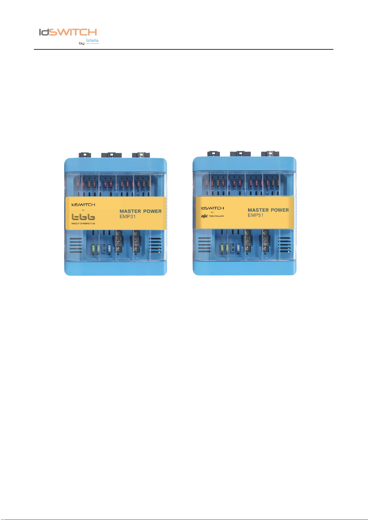
2. EMP31/EMP51 INTRODUCTION.............................................................................................2
2.1 Features.............................................................................................................................2
2.2 LED Display.......................................................................................................................2
3. KEY FEATURES AND FUNCTIONS ........................................................................................3
3.1 Multiple inputs....................................................................................................................3
3.2 Battery Charger of Auxiliary Battery ...................................................................................4
3.3 Lithium battery charging.....................................................................................................5
3.4 Power Supply Mode...........................................................................................................5
3.5 PWM Solar charger controller............................................................................................5
3.6 Voltage Charging Relay (VCR )..........................................................................................6
3.7 Battery Low Voltage Protection (BLVP)..............................................................................7
3.8 DC Distribution...................................................................................................................8
4. STRUCTURE AND INSTALLATION.........................................................................................9
4.1 EMP Master Power Unit.....................................................................................................9
4.2 Installation........................................................................................................................12
4.3 Fuse specification............................................................................................................13
5. OPERATION..........................................................................................................................14
5.1 Configuration on EMP......................................................................................................14
5.1.1 Dip switch setting...................................................................................................14
5.2 Daily Maintenance ...........................................................................................................16
6. Trouble shooting.....................................................................................................................16
6.1 LED display on EMP........................................................................................................16
7.Specification ..............................................................................................................................17

EMP31/EMP51 Master Power Unit User Manual
IDM Technologie
1
1. General Safety Instruction
1.1 Safety Instruction
As dangerous voltages and high temperature exist within the EMPMaster Power Unit, only qualified
and authorized maintenance personnel are permitted to open and repair it. Please make sure the
unit is turned off before open and repair it.
This manual contains information concerning the installation and operation of EMP Master Power
Unit. All relevant parts of the manual should be read prior to commencing the installation. Please
follow the local stipulation meantime.
Any operation against safety requirement or against design, manufacture, safety standard, and are
out of the manufacturer warranty.
1.2 General Precaution
1) Do not expose to dust, rain, snow or liquids of any type,it is designed for indoor use. DO NOT
block off ventilation, otherwise the EMP Master Power Unit would be overheating.
2) To avoid fire and electric shock,make sure all cables selected with right gauge and being
connected well. Smaller diameter and broken cable are not allowed to use.
3) Please do not put any inflammable goods near to this unit.
4) Never place this unit directly above batteries, gases from a battery will corrode and damage
EMP Master Power Unit.
5) Do not place battery over EMP Master Power Unit.
1.3 Precaution regarding battery operation
1) Use plenty of fresh water to clean in case battery acid contacts skin, clothing, or eyes and
consult with doctor as soon as possible.
2) The battery may generate flammable gas during charging. NEVER smoke or allow a spark or
flame in vicinity of a battery.
3) Do not put the metal tool on the battery, spark and short circuit might lead to explosion.
4) REMOVE all personal metal items such as rings, bracelets, necklaces, and watches while
working with batteries. Batteries can cause short-circuit current high enough to make metal
melt, and could cause severe burns.

EMP31/EMP51 Master Power Unit User Manual
IDM Technologie
2
2. EMP31/EMP51 INTRODUCTION
2.1 Features
➢Smart battery charger 12V18A (EMP31) / 12V30A(EMP51)
Active PFC charging
➢16 Fused DC outputs, including water pump and lighting central control.
➢Battery charging relay 12V 30A
➢Battery Low Voltage Protection
➢Support external remote main switch
➢Control one water pump with two tank probes
➢Solar charger controller (PMW), 15A
2.2 LED Display
Table 1 LED indication
NO.
LED
Color
Status
Description
1
CHG
Green
ON
Battery charged
Flashing
(flash once every second)
Battery charging
OFF
Battery discharge
2
Dischg
Orange
ON
Battery discharging
OFF
Battery charging
3
CHG/ Dischg
Green/Orange
Both ON
Power supply

EMP31/EMP51 Master Power Unit User Manual
IDM Technologie
3
3. KEY FEATURES AND FUNCTIONS
3.1 Multiple inputs
EMP master power unit may have multiple sources at one time. These sources include the Shore
power, Solar panel and Alternator (Motor battery). There is priority among these sources, but EMP
allows several sources to charge auxiliary battery at the same time. The priorities are listed below.
Table 2 Energy sources priority
AC Mains
✓
✓
✓
Solar panel
✓
✓
✓
✓
Alternator (Motor battery)
✓
✓
✓
Dominating Source
AC mains
+ Solar
panel
AC mains
+ Solar
panel
AC mains
Alternator +
Solar panel
Solar panel

EMP31/EMP51 Master Power Unit User Manual
IDM Technologie
4
3.2 Battery Charger of Auxiliary Battery
The charger automatically starts when the appropriate qualified power is connected, either from grid,
generator. With multiple charging stages (soft start-bulk-absorption-float-recycle), EMP is designed
to fully charge battery quickly. To guarantee the optimal charging for batteries of different states, the
EMP features Microprocessor-controlled charging algorithm. The Float and Recycle charging
programs guarantees the battery being charged properly when battery is connected for a longer
period.
Figure 1 Charging algorithm for lead-acid battery of EMP31
Figure 2 Charging algorithm for lead-acid battery of EMP51

EMP31/EMP51 Master Power Unit User Manual
IDM Technologie
5
3.3 Lithium battery charging
The EMP can be configured to charge Lithium battery.
3.4 Power Supply Mode
If no battery is attached to EMP unit, it will work as a power supply automatically with a 12.8VDC
output.
3.5 PWM Solar charger controller
EMP has a built-in PWM charger for the auxiliary battery.
Max open circuit voltage is 30VDC
Max supply current is 15A

EMP31/EMP51 Master Power Unit User Manual
IDM Technologie
6
3.6 Voltage Charging Relay (VCR )
EMP Master Power Unit has a built-in voltage charging relay (VCR), which can get power from
alternator to supply the system and charge auxiliary whilst the engine is running.
Here is the working logic of VCR
Table 3 VCR working logic
D+ Enabled
D+ Disabled
LFP battery
Disengage
VCR will be disengaged
immediately if no D+ is
sensed or detected
VCR will be disengaged
when alternator/motor
battery’s voltage is less than
13.5V and charging current
is less than 2A for 60S
Engage
VCR will be engaged when:1)
D+ is sensed or detected; 2)
Alternator or motor battery’s
voltage is greater than 14.0V
for 10S
VCR will be engaged when
alternator or motor battery’s
voltage is greater than
14.0V for 10S
AGM/GEL
battery
Disengage
VCR will be disengaged
immediately if no D+ is
sensed or detected
VCR will be disengaged
when alternator or motor
battery’s voltage is less than
12.8V for 60S
Engage
VCR will be engaged when:1)
D+ is sensed or detected; 2)
Alternator or motor battery’s
voltage is greater than 12.0V
for 10S
VCR will be engaged when
alternator or motor battery’s
voltage is greater than
13.4V for 10S
Remarks:
a. D+ enabled means the EMP box has sensed or detected D+ once, afterwards EMP31 box
would deem it as D+ enabled
b. D+ disabled means the EMP box has never sensed or detected D+, so EMP box would
deem it as D+ disabled

EMP31/EMP51 Master Power Unit User Manual
IDM Technologie
7
3.7 Battery Low Voltage Protection (BLVP)
EMP31 master power unit has a built-in low voltage protection relay. The protection is decided by
battery type lithium battery or lead acid battery. Below please find the protection and resume value:
Table 4 Low voltage protection and resume
Protection
Threshold value
Low voltage protection
AGM/GEL/WET:10.8+/-0.3Vdc
LFP: 11.2+/-0.3Vdc
Low voltage protection resume
AGM/GEL/WET: 11.8+/-0.3Vdc
LFP: 12.2+/-0.3Vdc
Remarks:
a. There will be 60 seconds as time delay before above protection or resume

EMP31/EMP51 Master Power Unit User Manual
IDM Technologie
8
3.8 DC Distribution
Figure 2 DC distribution schematic diagram of auxiliary and motor battery

EMP31/EMP51 Master Power Unit User Manual
IDM Technologie
9
4. STRUCTURE AND INSTALLATION
4.1 EMP Master Power Unit
Figure 3 Connectors at front and back
Table 5 Connectors and terminals
No.
DEFINITION
LABEL
DESCRIPTION
1
/
AC Input
AC input port
2
/
PV
Connect to PV Panel
3
/
Fridge
Connect to fridge
4
/
Lifting Bed
Connect to lifting bed
5
/
Motor BAT
Connect to Motor BAT
6
/
AUX BAT
Connect to AUX BAT
7
Loads
[1]1
POS : Awning lamp
[1]2
GND : Awning lamp
[1]3
POS : Info D+ Fridge
[1]4
POS : Side lights
[1]5
GND : Side lights
[1]6
POS : Info D+ SAT antenna
[1]7
POS : Pump + WC
[1]8
GND : Pump + WC
[1]9
POS : Info D+ Preheating pump
[1]10
POS : Autoradio Signal
[1]11
GND :
[1]12
GND :
[1]13
POS : Oven + Piezo
[1]14
GND : Oven +Piezo
[1]15
GND : Buzzer Footstep

EMP31/EMP51 Master Power Unit User Manual
IDM Technologie
10
8
Loads
[2]1
POS : P6 lighting right side
[2]2
GND : P6 lighting right side
[2]3
POS : Buzzer Footstep
[2]4
POS : P6 lighting left side
[2]5
POS : P6 lighting left side
[2]6
GND: In/Out Footstep (COM)
[2]7
NOT USED
[2]8
NOT USED
[2]9
Out Footstep (Normally Open)
[2]10
POS + Fuse holders
[2]11
GND –Fuse holders
[2]12
In Footstep (Normally Open)
[2]13
POS + 12V socket
[2]14
GND –12V socket
[2]15
M1 - Footstep
[2]16
POS + USB socket
[2]17
GND –USB socket
[2]18
M2 Footstep
9
Loads
[3]1
POS : Permanent Autoradio
[3]2
GND : SAT antenna
[3]3
POS : SAT antenna
[3]4
POS : Combi + TRUMA/ALDE control
[3]5
GND : Combi + TRUMA/ALDE control
[3]6
GND : Elec Fridge
[3]7
POS : TV
[3]8
GND : TV
[3]9
POS : Elec. Fridge
10
Signal terminal
[7]1
D+ (active high +BAT
[7]2
Switch ON/OFF (Main)
[7]3
D+ (active down GND)
[7]4
DRY1_COM
[7]5
Sidelights (active high +BAT)
[7]6
+APC (active high +BAT)
[7]7
Sidelights (active down GND)
[7]8
+APC (active down GND)
[7]9
Switch ON/OFF (NO)
[7]10
Footboard End of stroke (COM)
[7]11
Footboard End of stroke (NO)
[7]12
DRY1_NO
11
Water tank
[6]1
[6]2
[6]3
[6]4
[6]5

EMP31/EMP51 Master Power Unit User Manual
IDM Technologie
11
[6]6
[6]7
[6]8
12
Water tank
[5]1
RSE_CLOCK1
[5]2
RSE_DATA1
[5]3
VCC_12V
[5]4
GND2
[5]5
[5]6
13
Signal control
(RJ11)
[4]1
IO_FROM_VCU
[4]2
IO_TO_VCU
[4]3
[4]4
14
CI Bus port
[9]1
VCC_12V
[9]2
[9]3
LIN
[9]4
[9]5
GND2
[9]6
15
Communication
port
[8]1
VCC_12V
[8]2
GND2
[8]3
[8]4
CANH
[8]5
CANL
[8]6
[8]7
VCC_12V
[8]8
GND2
16
DIP Switch
1 VCR
Set the battery type, VCR and Mode
2 Mode
3 Bat type
4 Bat type

EMP31/EMP51 Master Power Unit User Manual
IDM Technologie
12
4.2 Installation
For good ventilation, ensure empty space of at least 5 cm on each side of the EMP unit.
Figure 4 Installation
Figure 5 Dimensions of EMP

EMP31/EMP51 Master Power Unit User Manual
IDM Technologie
13
4.3 Fuse specification
Here is a list for the fuses installed on EMP. Please also take reference of Figure 2.
Table 6 Fuse specification list
Fuse No.
DC loads
Specification
F2
Awning light
5A
F3
Pump
10A
F4
Auxiliary
10A
F5
Kitchen piezo/oven
10A
F6
P6 1#
20A
F7
P6 2#
20A
F9
Fuse holders
20A
F10
USB sockets
10A
F11
12V sockets
20A
F12
Permanent SATAntenna
10A
F13
Permanent Autoradio
20A
F14
Permanent Heating System
10A
F15
Permanent TV-Demodulator
10A
F16
Lifting Bed
25A
F18
Permanent Fridge
20A
F19
Footboard
20A
F20
AUX BAT
50A
F21
Motor BAT
50A
F1
By-pass Pump
25A
F8
By-pass Lighting
25A
F17
By-pass Lifting
25A

EMP31/EMP51 Master Power Unit User Manual
IDM Technologie
14
5. OPERATION
5.1 Configuration on EMP
You can set the battery type, VCR mode and working mode by the dip switch of EMP
Dip switch #2 (working mode) always needs to be OFF. For dip switches #1, 3 and 4, settings
made from a connected tablet have priority.
5.1.1 Dip switch setting
There are dip switches for you to set VCR mode, Working mode and Battery type.
Figure 6 Dip switch - Example of LFP battery
Table 7 Dip switch definition
DIP SWITCH
1
2
3
4
VCR mode /
Booster
Working mode
Battery type
5.1.1.1 Dip switch for VCR mode and Working mode
Table 8 Dip switch for VCR mode and Working mode selection
VCR mode
OFF
Built-in VCR is enabled (Default setting)
ON
Built-in VCR is disabled
Working mode
OFF
Charger (Default setting)
ON
Power supply
a) VCR mode
There are two VCR modes for optional:
- Built-in VCR is enabled: When this mode is selected, the integrated VCR is activated; please see
more details how VCR works in Table 3
- Built-in VCR is disabled: When this mode is selected, the integrated VCR is deactivated and the
relay will remain as disengaged; an external booster could be added when built-in VCR is disabled

EMP31/EMP51 Master Power Unit User Manual
IDM Technologie
15
b) Working mode
There are two working modes for optional:
- Charger: When this mode is selected, the EMP will operate as a charger to charge the auxiliary
battery as long as the grid 230V or qualified PV is introduced
- Power supply: when this mode is selected, the EMP will provide a stable output 12.8Vdc 18A to
power the connected DC loads
5.1.1.2 Dip switch for battery type
Table 9 Dip switch for battery type setting
Switch #3
Switch #4
Battery type
OFF
OFF
AGM
OFF
ON
GEL
ON
OFF
LFP
ON
ON
WET
5.1.1.3 External Main Switch (Optional)
EMP offers a possibility to connect with an external main switch, which allows user to turn on/off the
EMP remotely.
Figure 7 Main switch
Figure 8 Wiring diagram of main switch

EMP31/EMP51 Master Power Unit User Manual
IDM Technologie
16
5.2 Daily Maintenance
➢Check and insure the nominal battery voltage is 12Vdc.
➢When replacing the existing battery with a new one, please have the new battery fully charged
by Grid for the first time use
6. Trouble shooting
6.1 LED display on EMP
Table 10 Error LED indicator of EMP
NO.
LED
Color
Status
Description
1
CHG /
DISCHG
Green
/ Orange
Flash once per cycle
Auxiliary battery voltage low
2
Flash twice per cycle
Auxiliary battery voltage high
3
Flash 3 times per cycle
EMP over temperature
4
Flash 4 times per cycle
Bulk charge timeout
This manual suits for next models
1
Table of contents
Other BBB Portable Generator manuals
Popular Portable Generator manuals by other brands

iPower
iPower GXS4301i owner's manual

Generac Power Systems
Generac Power Systems NP45G Series technical information

Scheppach
Scheppach SG7300 Translation of original instruction manual

Wacker Neuson
Wacker Neuson GV 7000A Operator's manual

Consort
Consort EV202 manual

Westinghouse
Westinghouse WHC5500 owner's manual