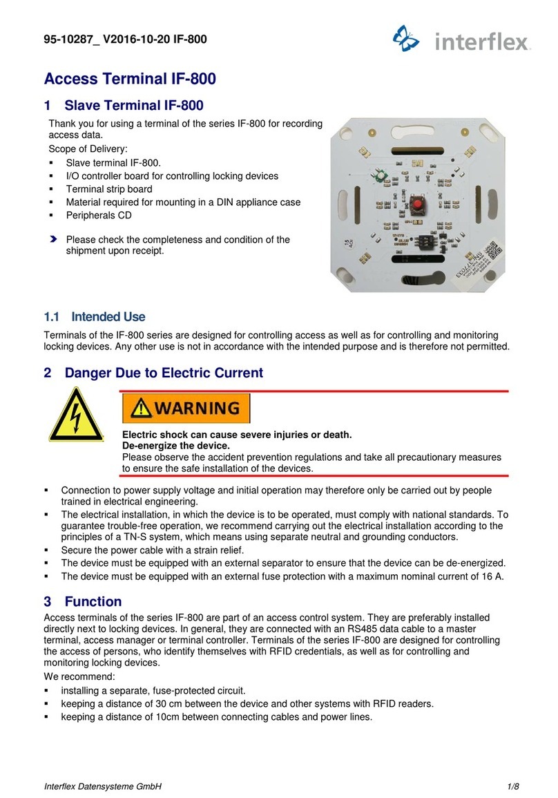
BBC Bircher DualSense D User manual

1 Description
1.1 Function
The detector is designed for installation above an automatic
pedestrian door and for connection to the door controller.
The detector registers the movement of people in front of the
door with a radar eld in order to open the door. The detector
registers people in the door’s area of movement with an AIR
(active infrared) eld to stop door movement.
1.2 Scope of delivery
The package contains:
• Detector with cover
• 3-meter connection cable with plug connector
• Lens covers for AIR area limitation
• Installation material
• Drilling jig
• Declaration of conformity
• Operating instructions
1.3 Conformity
The version of the device we have introduced complies with
the requirements of directives and standards in accordance
with the attached declarations of conformity.
2 OSafety instructions
Read these operating instructions carefully before
commissioning the device. Keep the instructions for future
use or follow the QR link to the web documentation.
2.1 Intended use
Only use this product for the function specied in the
description, see section →1.1. The manufacturer is only liable
for products used as intended. Do not modify the device.
2.2 Notes on installation
Only trained and qualied personnel may install and initialise
the device.
The installer is responsible for installing the door system
and this product in accordance with the regulations and
standards.
2.3 General safety instructions
If installation according to EN 61558 is required, the detector
may only be operated using safety extra-low voltages (SELV)
with safe electrical isolation. The cables must be protected
against mechanical damage.
Activation and safety for automatic sliding doors in acc. with EN 16005
including emergency exits
DualSense D
EN Translation of the original instructions English 465846 A
1 LED red (AIR)
2 LED green (radar)
3 LED blue (without funktion)
4 AIR windows
5 Cover
1/2/3 LEDs (s.o.)
6 QR link web documentation
7 Display
8 Wiring label
9 AIR optics (4 lenses each)
10 AIR angle adjustment
11 Radar module
12 Joystick
13 Support plate
14 Mounting points
15 Cable strain relief
9 9
12
11
14
13
15
14
10
7
12
4 4 5
3
6
123
8
07.2023 © BBC Bircher / bircher.com DualSense D 1 / 8

2 / 8 DualSense D © BBC Bircher / bircher.com 07.2023
3 Installation
3.1 Installation positions
Note the following requirements:
• Surface must be stable, vibration-proof and grounded.
• Avoid proximity to uorescent lights, fans, currents of
warm air and ventilation systems.
• Protect the detector against extreme weather conditions
such as driving rain.
3.2 Mounting
1. Remove the cover from the detector.
2. If necessary, prepare the following mechanical settings
according to section →3.5: Align radar eld (rotate radar
module), limit AIR eld (cover lenses), pre-adjust AIR
inclination angle.
3. Stick the drilling template on the mounting location, drill a
cable hole.
4. Lay the connection cable. Ensure that the cable is
routed so that it is free of electromagnetic interference.
For example, avoid routing the cable parallel to the
connecting cable of the door drive.
5. Screw the support plate of the detector to the mounting
points.
Mounting on the door prole
3.3 Electrical connection
1. Disconnect the power supply to the door controller.
2. Plug the connection cable into the detector.
3. Connect the cable to the door controller as shown below.
The black/purple wire pair is only required for escape
routes.
4. Switch on the power supply to the door controller.
Wiring label
Function
Value
Select
11,5
-
32 V DC
Radar 34 V DC, 40 mA
Test
Radar voltage output
–
+
–
+
+
–
AIR 34 V DC, 40 mA
JoystickWiring
Function
Value
Select
11,5
-
32VDC
Radar 34VDC, 40mA
Test
Radar voltage output
–
+
–
+
+
–
AIR 34VDC, 40mA
JoystickWiring
Escape route
▶For automatic doors in escape routes, select one of these
connection types for the radar output:
a) Radar voltage output, black/purple wire pair (door
opens when no voltage is applied)
b) Radar 34 V DC, 40 mA, green/yellow wire pair in
combination with the parameter conguration →3.4
→Output RADAR with the value Frequency (door
opens when no oscillating signal is emitted)
Performance level PLd, Cat. 2 (EN ISO 13849-1)
▶Connect the test input to reach PLd.
3.4 Conguration
1. Press the joystick and follow the Quickstart menu shown
in the display. See below the explanation for →Navigation
and →Parameters.
2. If necessary, congure the setting for an →Escape route.
3. If necessary, optimize other parameters.
4. If desired, protect the conguration with a password.
5. Complete the conguration.
Navigation
Display
Joystick Action
Start conguration
Menu view
Select parameter group
Select parameters
Display value view of the parameter (exit
conguration in menu item Exit)
Werteansicht
Select value
Conrm value
return to the menu view
Value view
1 min motionless Conguration automatically nished
3 min motionless Conguration password protected
(if password set)
Parameters
Menu: Parameter group
Parameters Selection of a value
Quickstart
Select your menu language during initialization.
AIR eld Carry out the mechanical settings as described
in →3.5 →Safety-relevant function (AIR/active
infrared).
AIR sensitivity Select high from a mounting height of 3.0
m, medium from a mounting height of 2.6
m, normal from a mounting height of 2.2 m.
The low and very low settings are suitable for
special surface conditions. Ensure that the test
specimen is always reliably detected.
AIR frequency To avoid conicts between neighboring
detectors with overlapping infrared elds,
select dierent signal patterns.
Radar eld Size of the area for motion detection: Test the
appropriate setting.

07.2023 © BBC Bircher / bircher.com DualSense D 3 / 8
General
Language Menu language
Outputs Separate: Only radar detection opens the door,
Combined: Radar and AIR detection open the
door.
Default settings Default settings are typical parameter
combinations. Note: All parameters will be
overwritten. Then check which parameters may
need to be readjusted.
Reset Restart restarts the detector.
Factory settings deletes all manual settings,
including password.
Password Dialog for setting a password consisting of
4 digits. At 0000, the password protection
is inactive (factory setting). For any other
combination of digits, the password is
requested when the conguration menu is
started. 3 min after nishing the conguration
the menu is locked again.
If the password is lost, disconnect the detector
from the power source. After reconnection, the
conguration is open for 1 min to set a new
password.
Radar
Field See Radar eld in Quickstart menu
Direction
recognition
The Forward setting only detects movement
towards the door, Both also away from the
door.
Cross trac The Optimised setting reduces the response
to cross trac.
Filter Turning on the lter can reduce interference
from unwanted ambient eects. The lter also
lowers the sensitivity of the radar. Test this
setting if necessary.
Output RADAR
Function
Value
Select
11,5
-
32 V DC
Radar3 4 V DC, 40 mA
Test
Radarvol tage output
–
+
–
+
+
–
AIR 34 V DC, 40 mA
JoystickWiring
Function
Value
Select
11,5
-
32VDC
Radar 34VDC, 40mA
Test
Radar voltage output
–
+
–
+
+
–
AIR 34VDC, 40mA
JoystickWiring
When motion is detected, active (NO) closes
the contact, passive (NC) opens the contact.
Frequency opens when signal frequency is
lost, therefore suitable for door in →Escape
route.
Function
Value
Select
11,5
-
32 V DC
Radar3 4 V DC, 40 mA
Test
Radarvol tage output
–
+
–
+
+
–
AIR 34 V DC, 40 mA
JoystickWiring
Function
Value
Select
11,5
-
32VDC
Radar 34VDC, 40mA
Test
Radar voltage output
–
+
–
+
+
–
AIR 34VDC, 40mA
JoystickWiring
Voltage output for radar does not require
conguration: set value can remain.
AIR
Sensitivity See AIR sensitivity in the Quickstart menu
Presence The selected time determines the time after
which a stationary object is recognized as a
normal environment.
Output AIR The switching logic active(NO) closes,
passive(NC) opens the contact when the
safety-relevant function is triggered. The
slave(NO) and slave(NC) settings are required
for series circuits.
Break The safety-relevant function can be switched
o for 15 minutes for maintenance work. The
red LED ashes during the break.
Frequency See Quickstart menu
Info
Log, operating
hours
Information for support requests in case of
need, error codes, operating hours counter.
Cong ID Current conguration of the detector as a QR
code for photographing.
AIR signal Monitor of the 3 AIR channels to analyze the
signal reception, absolute (top) and relative to
the switching point (bottom).
The AIR signal monitor is displayed without
a time limit (without TimeOut function, see
→Navigation).
SW, HW Software and hardware version.
Exit
Exit conguration

4 / 8 DualSense D © BBC Bircher / bircher.com 07.2023
3.5 Mechanical settings
Motion detection (radar)
The detector uses a radar eld to detect people approaching
the door.
▶ To adjust the alignment of the radar eld, rotate the radar
module.
Wide radar eld:
Standard
1m
2m
3m
1m
2m
0m
0m
1m
2m
3m
4m
Narrow radar eld:
e.g. in narrow corridors
1m
2m
3m
1m
2m
0m
0m
1m
2m
3m
4m
90°
Rotation of radar module:
1. Loosen the snap-in hook on
the right
2. Rotate module by 90°
3. Press module into snap-in
hook
▶Set the inclination angle and the swivel angle of the radar
eld.
+
−
With the inclination angle, you
set the distance from the door
at which people are detected.
–
–
+
+
+−
If the building situation
requires it, swivel the
radar eld to the side.
–
–
+
+
Safety-relevant function (AIR/active infrared)
The detector monitors the door’s area of movement with
an AIR eld of 24 light cones. Four lenses bundle the eld
into segments A to D. The size of the eld depends on the
mounting height of the detector (drawing with example values
for H = 220 cm).
H (220)
W
(200)
D (20)
A
A
B
B
C
C
D
D
ABCD
If the AIR eld is too wide for the installation situation, the
width can be adjusted segment by segment.
AB
B
CD
A
A
A
A
BC
D
D
D
D
D
ABC
C
D
D
A
A
A
A
B
B
B
B
CD
Example:
narrow door
Example:
Primary closing edge left
▶To adjust the eld width, cover lenses A to D as required.
Use the enclosed plastic plates and the slots in front of
the lenses for this purpose.
A
A
B
B
C
C
D
D
ABCD
11.3 mm 9.0 mm
A /
DB
/ C

07.2023 © BBC Bircher / bircher.com DualSense D 5 / 8
The inclination angle of the AIR eld is continuously
adjustable from -5 to +7°.
▶ Adjust the inclination angle so that the AIR eld on the
oor is 5 to 8 cm from the door.
▶Test the setting with a standard-compliant test specimen.
The AIR eld must detect the test specimen in the area of
movement of the door. The AIR eld must not cover the
door.
d
R
a
H
+
−
1
2
3
4
AIR angle adjustment
1 Setting screw
2 Scale (1° per line)
3 Pointer
4 Position 0°
H Mounting height of
detector
R Depth lintel in front of
door leaf
a Inclination angle
d distance eld in front of
door
Guide values for the inclination angle a:
(mm) Depth R
Height H 0 50 100 150 200 250 300
1800 6° 5° 3° 1° 0° -2° -3°
2000 6° 5° 3° 2° 0° -1° -3°
2200 6° 4° 3° 2° 0° -1° -2°
2400 6° 4° 3° 2° 1° 0° -2°
2600 5° 4° 3° 2° 1° 0° -1°
2800 5° 4° 3° 2° 1° 0° -1°
3000 5° 4° 3° 2° 1° 0° -1°
3200 5° 4° 3° 2° 1° 1° 0°
3400 5° 4° 3° 2° 2° 1° 0°
3600 5° 4° 3° 2° 2° 1° 0°
3800 5° 4° 3° 2° 2° 1° 0°
4000 5° 4° 3° 2° 2° 1° 0°
3.6 Initialisation
1. Remove all objects from the door area that do not form
part of the usual door system environment. Make sure
that there are no people in the door area.
2. Restart the detector. Quickly leave the security area of the
door. The detector now detects the normal environment
in the safety area.
3. Wait until the LEDs stop ashing (approx. 30 s.).
4. Note: Continued ashing signals indicate an error. Check
the connections and the free door area, restart the
initialisation.
5. Test the door system and, if necessary, modify the
mechanical settings according to section →3.5 and the
software conguration according to section →3.4.
ODie Sicherheitsfunktion des Sensors muss hinreichend
empndlich zur Personenerkennung eingestellt sein.
Observe the behavior of the door and the display of the
signal monitor in the menu under Info →AIR signal.
6. Place the cover on the detector. Use the guide groove
between the two AIR lenses for this purpose.

6 / 8 DualSense D © BBC Bircher / bircher.com 07.2023
4 Operation and maintenance
4.1 Regular work
▶At least once a year, remove dust from the inside the AIR
windows.
▶At least once a year, test the safety-relevant function of
the door system.
4.2 LED signals
LED Bedeutung
green – moving object in radar eld
red – new object in AIR eld
red ashing – AIR start
– AIR signal too strong/weak
– AIR break, 15 minutes
red and green
ashing alternately
– detector restart (6seconds)
red and green
ashing at the same time
– power supply faulty
– detector defective
4.3 Faults
Door fault
LED signal
Possible cause ▶Remediation options
Door opens and closes alternately with no one present
LED green
Radar detects door movement ▶Mechanical adjustment:
Increase the inclination angle
of the radar eld (away from the
door).
▶ Radar conguration: Reduce
the size of the eld.
Door opens with no one present
LED green
Moving objects in the radar eld ▶ Remove plants, signs, ags
from the radar eld.
Radar interference due to
vibration of the detector
▶Fix the mounting point of the
detector.
Radar interference by uorescent
lights
▶ Use a dierent kind of
lighting.
Radar interference by further
detector
▶ Radar conguration: Activate
the lter.
▶ Radar conguration: Reduce
the size of the eld.
▶Mechanical adjustment: Pan
the radar eld away from the
interfering radar eld.
Door does not close
LED red
AIR detects door movement ▶Mechanical settings: Increase
the inclination angle of the radar
eld (away from the door).
Moving objects in the AIR eld ▶ Remove plants, signs, ags
from the radar eld.
AIR interference due to vibration
of the detector
▶Fix the mounting point of the
detector.
AIR interference by uorescent
lights
▶ Use a dierent kind of
lighting.
AIR interference due to puddles
of water or snowfall
▶Decrease the AIR sensitivity
(conguration).
OCaution! Safety-relevant
function may be impaired.
AIR interference due to further
detector
▶ AIR conguration: Select
another frequency.
AIR interference due to door
drive or other electromagnetic
inuences
▶Optimize the cable routing
according to → 3.2 (step 4) and/
or reduce the AIR sensitivity
(conguration).
OCaution! Safety-relevant
function may be impaired.
Door does not move
LEDs o
Safety-relevant function is
congured incorrectly
▶ AIR conguration: Switch
the output between active and
passive.
LED red ashing
Display: Message A2002
AIR signal too weak
▶Clean the AIR light windows
and restart the detector
(conguration/general/reset).
▶Mechanical settings: Readjust
the angle of the AIR eld.
Check the eect on the signal
strength in the signal monitor
(conguration info: AIR sign).
▶ Cover light-absorbing oors
in the AIR eld with a light-colored
surface. Check the eect on the
signal strength (conguration
info: AIR sign).
Display: Message A2003
AIR signal too strong
▶Mechanical settings: Readjust
the angle of the AIR eld.
Check the eect on the signal
strength in the signal monitor
(conguration info: AIR sign).
▶ Cover reective oors in
the AIR eld with a matt surface.
Check the eect on the signal
strength (conguration info: AIR
sign).
LED red and green ashing at the same time
Display: Message A2004...A2007
Supply voltage too low
▶Ensure that the supply
voltage is sucient. If the supply
voltage is guaranteed according
to the technical data, replace the
detector
Display: Message E ...
Detector defective
▶Replace the detector.

07.2023 © BBC Bircher / bircher.com DualSense D 7 / 8
4.4 Spare parts
Only use original spare parts from the manufacturer. Make
sure that you do not technically modify the product by
repairing it.
4.5 Dismantling, disposal
The product contains electrical or electronic
components. In case of disassembly, observe the
disposal regulations applicable locally.
5 Technical data
Housing material ABS / PA
Housing color black, silver, white
Dimensions (L × W × D) 252 × 61 × 51 mm
Weight 250 g
Radar transmission frequency 24.2 GHz
Radar output < 13 dBm
Performance level PLd, Cat. 2 (EN ISO 13849-1),
test signal from door controller
required
11.5...32 V DC
Supply voltage 11.5...32 V DC
Operating current max. 120 mA at 24 V
Inrush current max. 240 mA
Test input, high level 5…32 V DC, max. 4 mA
Response time to test signal < 10 ms
Outputs (infrared/radar) Solid state relay, max. 34 V DC /
24 V AC, max. 40 mA
Mounting height min. 1.8 m, EN 16005 up to 3.0 m,
max. 4.0 m
Ambient temperature min. –20 °C, max. +60 °C
Protection class IP54 (EN 60529)
Air humidity Max. 95 % relative, non-
condensing
6 Contact
If you have any questions about the detector, please contact
us: support@bircher.com, Phone +41 52 687 1366
BBC Bircher Smart Access, BBC Bircher AG
Wiesengasse 20, CH-8222 Beringen, www.bircher.com
Designed in Switzerland / Made in China

8 / 8 DualSense D © BBC Bircher / bircher.com 07.2023
Table of contents
Popular Wireless Access Point manuals by other brands
Ubiquiti
Ubiquiti PowerBeam PBE2ACN quick start guide

Planex
Planex GW-AP54SAG user manual
TRENDnet
TRENDnet TPL-110AP - 125Mbps 802.11g Wireless Powerline Access... Specifications
Samsung
Samsung WEA403i Quick installation manual
Cisco
Cisco Aironet 1700 Deployment guide
Extreme Networks
Extreme Networks WS-AP3805i quick reference
LevelOne
LevelOne WAP-6015 Quick installation guide

Pakedge
Pakedge WA-4200 user guide
LevelOne
LevelOne WAP-8021 Quick installation guide
ZyXEL Communications
ZyXEL Communications ZyXEL ZyAIR B-1000 Specifications
Linksys
Linksys WAP54G v2 user guide
Extreme Networks
Extreme Networks AP510C Hardware user's guide
