BC Group International BC Biomedical SA-2600 User manual

ELECTRICAL
SAFETY ANALYZER
WITH PATIENT SIMULATOR
SA-2600
USER MANUAL


i
WARNINGS, CAUTIONS, NOTICES...............................................................................ii
DESCRIPTION................................................................................................................1
LAYOUT..........................................................................................................................4
GETTING STARTED....................................................................................................... 6
TESTING.........................................................................................................................9
PATIENT SIMULATOR................................................................................................. 15
AUTOSEQUENCES ..................................................................................................... 16
SETTINGS....................................................................................................................22
MANUAL REVISIONS...................................................................................................25
LIMITED WARRANTY...................................................................................................25
SPECIFICATIONS ........................................................................................................ 26
NOTES.......................................................................................................................... 30
BC BIOMEDICAL
SA-2600 SERIES
TABLE OF CONTENTS
This User Manual covers the following units:
•SA-2600
•SA-2600-INTL
•SA-2600-AUS
ii
WARNING - USE
The SA-2600 is intended for testing only and
should never be used in diagnostics, treatment,
or any other capacity where they would come in
contact with a patient.
WARNING - MODIFICATIONS
The SA-2600 is intended for use within the
published specifications. Any application
beyond these specifications or any unauthorized
user modifications may result in hazards or
improper operation.
WARNING - CONNECTIONS
All connections to patients must be removed
before connecting the DUT to the SA-2600. A
serious hazard may occur if the patient is
connected when testing with the SA-2600. Do not
connect any leads from the patient directly to the
SA-2600 or DUT while it is powered by the SA-
2600.
WARNING - CLEANING
Disconnect Line Power to the SA-2600 before
attempting to clean it. Do not immerse. The SA-
2600 should be cleaned by wiping gently with a
damp, lint-free cloth. A mild detergent can be
used if desired.
CALIBRATION INTERVAL
To ensure the accuracy of the SA-2600, BC
Group International, Inc. recommends that it be
calibrated at least once every 12 months.
Calibration must be done by qualified personnel.
Contact BC Group International, Inc. for
calibration.

iii
WARNING - LIQUIDS
Do not submerge or spill liquids on the SA-2600.
In the event of a spill onto the SA-2600, Do not
operate the SA-2600 regardless of fluid type.
CAUTION - ENVIRONMENT
Exposure to environmental conditions outside
the specifications can adversely affect the
performance of the SA-2600. Allow SA-2600 to
acclimate to specified conditions for at least 30
minutes before attempting to operate it.
CAUTION - USAGE
The SA-2600 is not a continuous duty device, it
is intended for short duration testing within the
current limits and duty periods specified. Do not
leave the DUT connected to the SA-2600 for
extended time periods.
Do not to drop the SA-2600.
WARNING - VOLTAGE
When the SA-2600 is in Lead Isolation mode and
the ISO button is highlighted, 110% of line
voltage is applied to the Patient lead connectors
and/or External test leads. Although this voltage
is applied through an internal current limiting
resistance of 121 kΩ (per standard test
specifications), Do not touch the test leads,
connections or DUT while the ISO button is
highlighted.

iv
CAUTION - SERVICE
The SA-2600 is intended to be serviced only by
authorized service personnel. Troubleshooting
and service procedures should only be
performed by qualified technical personnel.
CAUTION - INSPECTION
The SA-2600 should be inspected before each
use for obvious signs of abuse or wear. The SA-
2600 should not be used and should be serviced
if any parts are in question.
NOTICE –SYMBOLS
Symbol
Description
Caution
(Consult Manual for Further Information)
Electrical Caution
(Consult Manual for Further Information)
Per European Council Directive 2002/95/EC,
do not dispose of this product as unsorted
municipal waste.
CAUTION - FUSE
Only replace the SA-2600 fuse with the specified
type and rating.

v
NOTICE –ABBREVIATIONS
Amp
Ampere(s)
AHA
American Heart Association
AAMI
Association for the Advancement of
Medical Instrumentation
BPM
Beats Per Minute
C
Celsius
cm
centimeter(s)
°
degree(s)
DUT
Device Under Test
ECG
Electrocardiogram
Euro
European
ft
feet
FS
Full Scale
Hz
hertz
IEC
International Electrotechnical Commission
ISO
Isolation
kg
kilogram(s)
kHz
kilohertz
kΩ
kilohm(s)
LED
Light Emitting Diode
MAP
Mains on Applied Parts
MHz
Megahertz
µA
microampere(s)
mA
milliampere(s)
mm
millimeter(s)
NEMA
National Electrical Manufacturers
Association
Ω
Ohm(s)
p-p
peak-to-peak
PC
Personal Computer
Lbs
pounds
RH
Relative Humidity
RMS
Root Mean Square
USA
United States of America
V
Volt(s)
VA
Volt-Ampere(s)
VAC
Volt(s) Alternating Current
W
Watt(s)
vi
SA-2600 Series User Manual Copyright © 2022
www.bcgroupintl.com Made in the USA
08/22 Rev 00
NOTICE –DISCLAIMER
BC GROUP INTERNATIONAL, INC. WILL NOT BE
RESPONSIBLE FOR ANY INJURIES SUSTAINED DUE TO
UNAUTHORIZED EQUIPMENT MODIFICATIONS OR
APPLICATION OF EQUIPMENT OUTSIDE OF THE PUBLISHED
INTENDED USE AND SPECIFICATIONS.
NOTICE –DISCLAIMER
BC GROUP INTERNATIONAL, INC. RESERVES THE RIGHT TO
MAKE CHANGES TO ITS PRODUCTS OR SPECIFICATIONS AT
ANY TIME, WITHOUT NOTICE, IN ORDER TO IMPROVE THE
DESIGN OR PERFORMANCE AND TO SUPPLY THE BEST
POSSIBLE PRODUCT. THE INFORMATION IN THIS MANUAL
HAS BEEN CAREFULLY CHECKED AND IS BELIEVED TO BE
ACCURATE. HOWEVER, NO RESPONSIBILITY IS ASSUMED
FOR INACCURACIES.
NOTICE –CONTACT INFORMATION
BC BIOMEDICAL
BC GROUP INTERNATIONAL, INC.
3081 ELM POINT INDUSTRIAL DRIVE
ST. CHARLES, MO 63301
USA
1-800-242-8428
1-314-638-3800
www.bcgroupintl.com
sales@bcgroupintl.com
NOTICE –PERFORMING TESTS
REFER TO DUT MANUFACTURER’S SERVICE MANUAL FOR
TEST PROCEDURES AND MEASUREMENT LIMITS.

1
The SA-2600 Series is an automated Electrical Safety Analyzer with a built-in Patient
Simulator. It allows for a multitude of tests to be performed on a device using the same
unit and lead connections. It provides a full Electrical Safety Analyzer, as well as ECG
Simulation with four waveforms with constant QRS duration and six machine performance
testing waveforms. There is Patient Lead testing for 10 inputs. There are programmable
autosequences to allow for limited user intervention testing. The following are highlights
of some of the main features:
SA-2600:
•4.3” LCD COLOR TOUCH DISPLAY
•AUDIO FEEDBACK
•TOUCH CONTROL KEYS –NO KNOBS
•10 UNIVERSAL PATIENT LEAD INPUTS
•HIGH IMPACT PLASTIC CASE
•CUSTOMIZABLE AUTOSEQUENCES
•FIXED GENERIC AUTOSEQUENCES
SAFETY ANALYZER:
•LINE VOLTAGE MEASUREMENT
•DEVICE UNDER TEST CURRENT MEASUREMENT
•EARTH / GROUND LEAD RESISTANCE
•EARTH / GROUND LEAKAGE CURRENT
•ENCLOSURE / CHASSIS LEAKAGE CURRENT
•PATIENT LEAD TO LEAD LEAKAGE CURRENT
•PATIENT LEAD TO EARTH / GROUND LEAKAGE CURRENT
•PATIENT ISOLATION LEAKAGE CURRENT
•POINT TO POINT RESISTANCE
•POINT TO POINT LEAKAGE CURRENT
•TRUE RMS MEASUREMENTS
•AAMI ES1-1993 or IEC 60601 SELECTABLE TEST LOADS
•90 TO 264 VAC OPERATION
•20 AMP RATING (SA-2600 and SA-2600-INTL Models)
•10 AMP RATING (SA-2600-AUS Models)
•SELF TEST POINTS
•EXTERNALLY REPLACEABLE GROUND FUSE
BC BIOMEDICAL
SA-2600 SERIES
ELECTRICAL SAFETY ANALYZER
WITH PATIENT SIMULATOR

2
PATIENT SIMULATOR:
•ECG: 30, 60, 120 AND 240 BPM
•SINE: 10, 60 AND 100 Hz
•SQUARE: 0.125 AND 2.0 Hz
•TRIANGLE: 2 Hz
•HIGH LEVEL OUTPUT (1 V p-p)
•AMPLITUDE ACCURACY: +/- 2%
•FREQUENCY ACCURACY: +/- 0.5%
AVAILABLE MODELS:
•SA-2600 –STANDARD MODEL WITH HOSPITAL-GRADE NEMA 5-15P LINE
PLUG AND HOSPITAL-GRADE NEMA 5-20R DUT TEST RECEPTACLE FOR
USE IN THE US AND OTHER COMPATIBLE COUNTRIES
•SA-2600-INTL –INTERNATIONAL MODEL, IEC C20 RECEPTACLE PIGTAIL
(MUST USE COUNTRY-SPECIFIC LINE CORD –SEE ACCESSORIES
SECTION) AND UNIVERSAL DUT TEST RECEPTACLE THAT WORKS WITH
THE FOLLOWING COUNTRY-SPECIFIC PLUGS:
oNEMA 5-15P, NEMA 5-20P, NEMA 6-15P and NEMA 6-20P (US/NORTH
AMERICA)
oUK1-13P and UK3-5P (UK)
oSW1-10P (SWITZERLAND)
oIT1-10P (ITALY)
oIS1-16P (ISRAEL)
oJA1-15P (JAPAN)
oEU1-16P (EURO) CEE 7/7 “SCHUKO” (NOTE: MUST USE SCHUKO
GROUNDING ADAPTER TO PERFORM LEAKAGE MEASUREMENTS,
SEE OPTIONAL ACCESSORIES SECTION)
oDE1-13P (DENMARK) (NOTE: NO EARTH/GROUND PIN, THEREFORE
LEAKAGE MEASUREMENTS NOT APPLICABLE)
oEUROPLUG CEE 7/16 (NOTE: NO EARTH/GROUND PIN, THEREFORE
LEAKAGE MEASUREMENTS NOT APPLICABLE)
•SA-2600-AUS –AUSTRALIAN MODEL, AU1-10P LINE PLUG AND AU1-10R
DUT TEST RECEPTACLE FOR USE IN AUSTRALIA/NEW ZEALAND AND
OTHER COMPATIBLE COUNTRIES
STANDARD ACCESSORIES
•BC20-20110 8 FT CHASSIS TEST LEAD (BLACK)
•BC20-17026 GROUND PIN
•BC20-30107 SOFT CARRYING CASE
•UF-0250-01 REPLACEMENT GROUND LEG FUSE
•BC20-204XX POWER CORD (SA-2600-INTL ONLY) –REFER TO PAGE 6

3
OPTIONAL ACCESSORIES
•BC20-20111 8 FT EXTERNAL TEST LEAD (RED)
•BC20-20112 16 FT CHASSIS TEST LEAD (BLACK)
•BC20-20113 16 FT EXTERNAL TEST LEAD (RED)
•BC20-20200 REPLACEMENT SA-2600-INTL DUT INTERNATIONAL
RECEPTACLE ADAPTER
•BC20-20221 SCHUKO GROUNDING ADAPTER
•BC20-41377 MICRO USB CABLE (MICRO TO USB A)
SA-2600-INTL LINE CORDS: (REFER TO PAGE 6 FOR DETAILS)
•BC20-20400 NEMA 5-20P PLUG LINE CORD (USA/NORTH AMERICA)
•BC20-20401 JA1-15P PLUG LINE CORD (JAPAN)
•BC20-20402 UK1-13P PLUG LINE CORD (UK)
•BC20-20403 CEE 7/7 “SCHUKO” PLUG LINE CORD (EURO)
NOTE: INCLUDES BC20-20221 GROUNDING ADAPTER
•BC20-20409 BSS546A PLUG LINE CORD (INDIA/SOUTH AFRICA)
•BC20-20410 SW1-10P PLUG LINE CORD (SWITZERLAND)
•BC20-20412 IT1-10P PLUG LINE CORD (ITALY)
•BC20-20416 AUSTRALIA PLUG LINE CORD

4
This section looks at the layouts of the SA-2600 Models and gives descriptions of the
elements that are present.
There is an audio click when any key is depressed, while a “Razz” or error tone consisting
of a rapid succession of beeps is sounded if an invalid key is depressed.
LAYOUT
4.3” LCD Display
with Touchscreen
NEMA 5-20R
Receptacle for
DUT
10 Universal Patient Lead Inputs
Chassis Connector
Analyzer Receptacle Control
keys & indicators:
•Hot
•Neutral
•Ground
•Polarity
Earth/Ground
Fuse
Test Snaps (Top
to Bottom):
•High Level (+)
•1.0 Ω
•100 uA
External Lead
Connector
Micro USB
connector
High Level Output
(ECG)
5
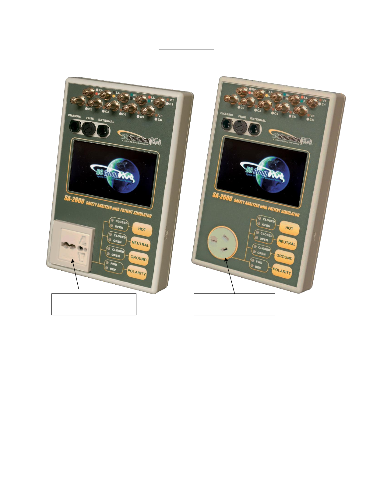
SA-2600 Layout
SA-2600-INTL Layout SA-2600-AUS Layout
The SA-2600-INTL and SA-2600-AUS Model Layouts are shown above, note that the
only differences from the standard model are the Line cords and the DUT test
Receptacles.
Universal International
Receptacle for DUT
Australian 10A @ 240V
Receptacle for DUT
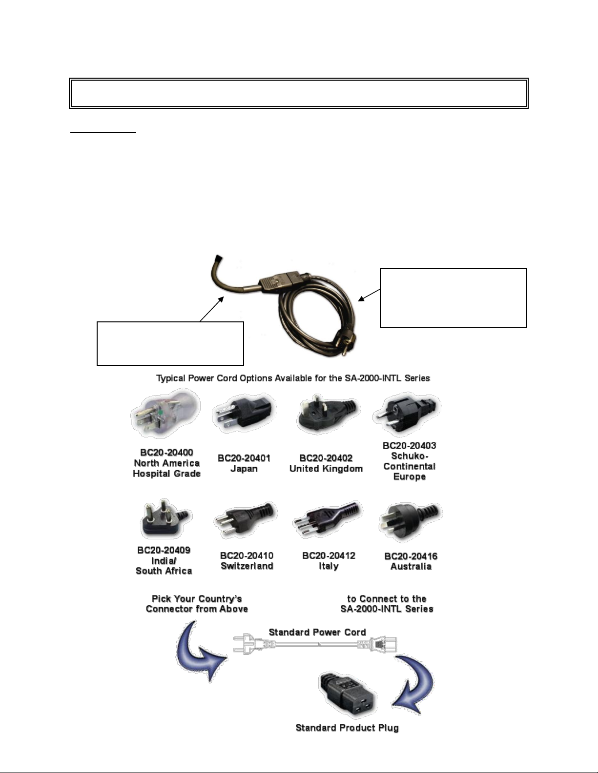
6
Power Cord
The Power Cord, which is connected internally, provides power to both the Safety
Analyzer and the DUT through the Test Receptacle. The Power Cord varies depending
on the Analyzer model. SA-2600 models use a NEMA 5-15P plug designed to plug into a
NEMA 5-15R or 5-20R Receptacle. SA-2600-INTL models have a short IEC C20 plug for
which a country-specific adapter cable must be connected –See the following section for
this information. SA-2600-AUS models use an Australian AU1-10P plug intended for
operation with Australian and New Zealand AU1-10R Receptacles.
GETTING STARTED
Adapter Cable with Standard
Product Plug and Required
International Connector
(See Options Below)
Universal Power Cord which
Connects to Standard Product
Plug

7
Analyzer Test Receptacle Control
There are four keys that allow the manual control of the power connections that are made
to the DUT.
Note: The Forward/Reverse Polarity key has a safety delay feature, preventing damage
to the internal relays and the DUT. When the key is depressed, the DUT power is disabled
and the safety delay is activated. When this delay is complete, the internal relays switch
the polarity to the DUT and apply power. This delay allows any reactive power stored in
the DUT to self-discharge before the polarity is reversed.
Note: The unit will power up with the Hot Open, Neutral Closed, and Ground Closed, and
in Forward Polarity. It is recommended that the unit be returned to this condition when
plugging and unplugging the DUT.
Connectors
There are two connectors for test cables on the unit. One is for the Chassis lead and the
other is for one of two different leads used for point to point testing. The test cables simply
plug into the sockets. There is a release pin on the cable plug that must be depressed to
remove the cable.
Universal Patient Lead Connectors
The 10 Universal Patient Lead Connectors allow for 12 lead ECG simulation with
independent outputs. AHA and IEC color-coded labels are located on the face of the unit
to aid in connecting the corresponding U.S. and International Patient Leads.
AHA Label
IEC Label
Description
RA
R
Right Arm
LA
L
Left Arm
RL
N
Right Leg
(reference or ground)
LL
F
Left Leg
V1
V2
V3
V4
V5
V6
C1
C2
C3
C4
C5
C6
V Leads (V1-V6)
(U.S. and Canada)
also referred to as pericardial,
precordial or unipolar chest leads
Chest Leads (C1-C6)
(International)

8
HI Level Output (+)
A HI Level connector is located on the side of the unit for the high level ECG output signal
(1 V p-p). The connection is between the High Level (+) snap and the RL (-) ECG lead.
Self-Test Snaps
There are two snaps on the side of the unit that allow for a quick self-test of the Analyzer.
They provide a fixed 1.0 Ohm resistance to Earth/Ground and a 100 µAmp leakage
current source to Earth/Ground when the Chassis lead is applied and the Analyzer set to
the Earth Resistance or Enclosure Leakage respectively.
Note: The fixed 1.0 Ohm resistance Self-Test Snap is measured without a Zero Offset
applied, see Page 11 for Earth Resistance and Zero Offset information.
Fuse
There is a fuse in the ground leg of the Analyzer Test Receptacle. This is to help prevent
damage from excess ground current. It is located on the face for ease of replacement.
Communications
Bluetooth is available to communicate with the myBC Mobile app. The myBC Mobile app
allows for full remote control of the SA-2600 functions, storing test configurations, storing
test results, and more. Find myBC Mobile on Apple and Android App stores.
A micro-USB port is provided to update the SA-2600.

9
The SA-2600 Models allow the user a great deal of flexibility in testing. The information
in this section presents a systematic approach that is just one way to proceed. It is only
presented as a guide, and it is the responsibility of the user to establish which tests are
required.
The Analyzer requires a good Earth/Ground connection for operation. It should be
plugged into a “Hospital Grade” receptacle where available. This is necessary for both
valid test results and personal safety.
Power Receptacle Confirmation
Once plugged in, the first step is to ensure that the wall receptacle the Safety Analyzer is
plugged into is wired properly (Non-Isolated Power Systems Only). The status of the
receptacle is displayed at the top of the Home Screen and the Mains Voltage Screen.
There are 3 different Outlet Statuses:
Outlet Status
Description
Normal
Wall receptacle wired correctly
Open Ground
1: No ground on wall receptable
2: Isolated Mains Supply
3: Broken Fuse on SA-2600
4: Multi-Phase Supply
Reverse Polarity
Wall receptacle Line and Neutral are reversed
Note: These are only applicable for 120V Non-Isolated Power systems only.
TESTING
NOTICE –PERFORMING TESTS
REFER TO DUT MANUFACTURER’S SERVICE MANUAL FOR
TEST PROCEDURES AND MEASUREMENT LIMITS.

10
Mains Voltage Screen
The Mains Voltage Screen will display the Voltage that is present on the incoming power
lines. This is measured from Line to Neutral. Note that the voltage may drop when the
DUT is turned on. Ensure that this value is within the DUT specifications.
Device Current Screen
The Device Current Screen will display the current draw of the DUT. The Receptacle
should be configured with HOT-CLOSED, NEUTRAL-CLOSED, GROUND-CLOSED and
POLARITY-FWD. Refer to the Specifications section for current capacity and permitted
duty cycle for this test mode.
11
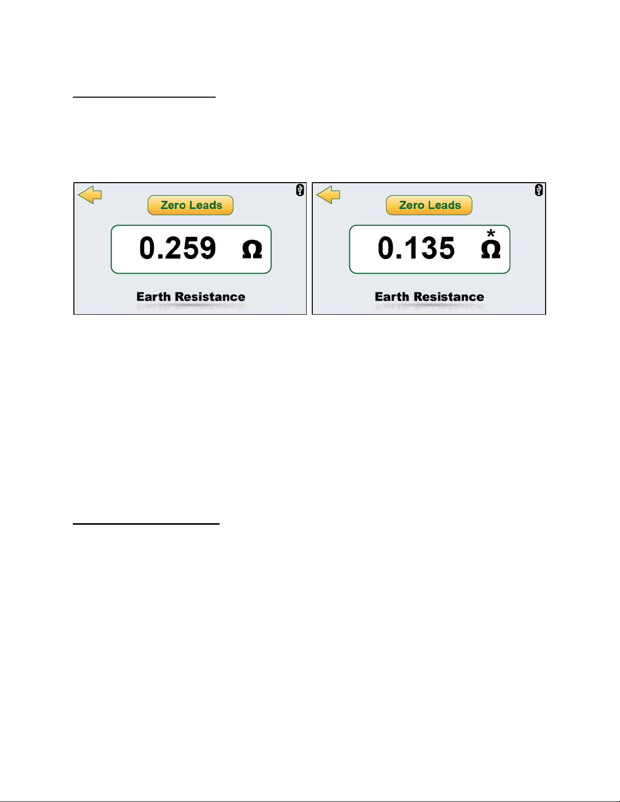
Earth Resistance Screen
The Earth Resistance Screen will display the resistance between the Chassis Test lead
and Receptacle Earth/Ground. This resistance is a combination of the resistance within
the DUT enclosure and the resistance of the Earth/Ground Lead in the DUT power cord.
The SA-2600 uses a 200 mA test current to measure the Earth Resistance.
NOTE: The test leads can be zeroed to get an accurate reading of the resistance. To zero
the leads, use the Ground Pin Adapter (BC20-17026) provided with the SA-2600 to
connect the chassis cable from the chassis port to the ground pin of the SA-2600
receptacle. Then tap the “Zero Leads”button, an asterisk (*) above the ohm symbol
indicates if there is an offset being applied to the reading. Pressing the “Zero Leads”
button while an offset is being applied will clear the stored offset.
This test has no meaning for equipment that does not use a grounded cord. The
receptacle will be configured with all contacts open.
The test requires that the Chassis Test lead be plugged into the Chassis Connector. The
other end should be connected to a solid ground point on the DUT.
Point to Point Resistance
Point to point resistance can be performed by removing the DUT power cable from the
receptacle. Then, plugging a second Chassis cable (BC20-21110 or BC20-21112) into
the external connector. The display will now read the resistance between the two cables.
12
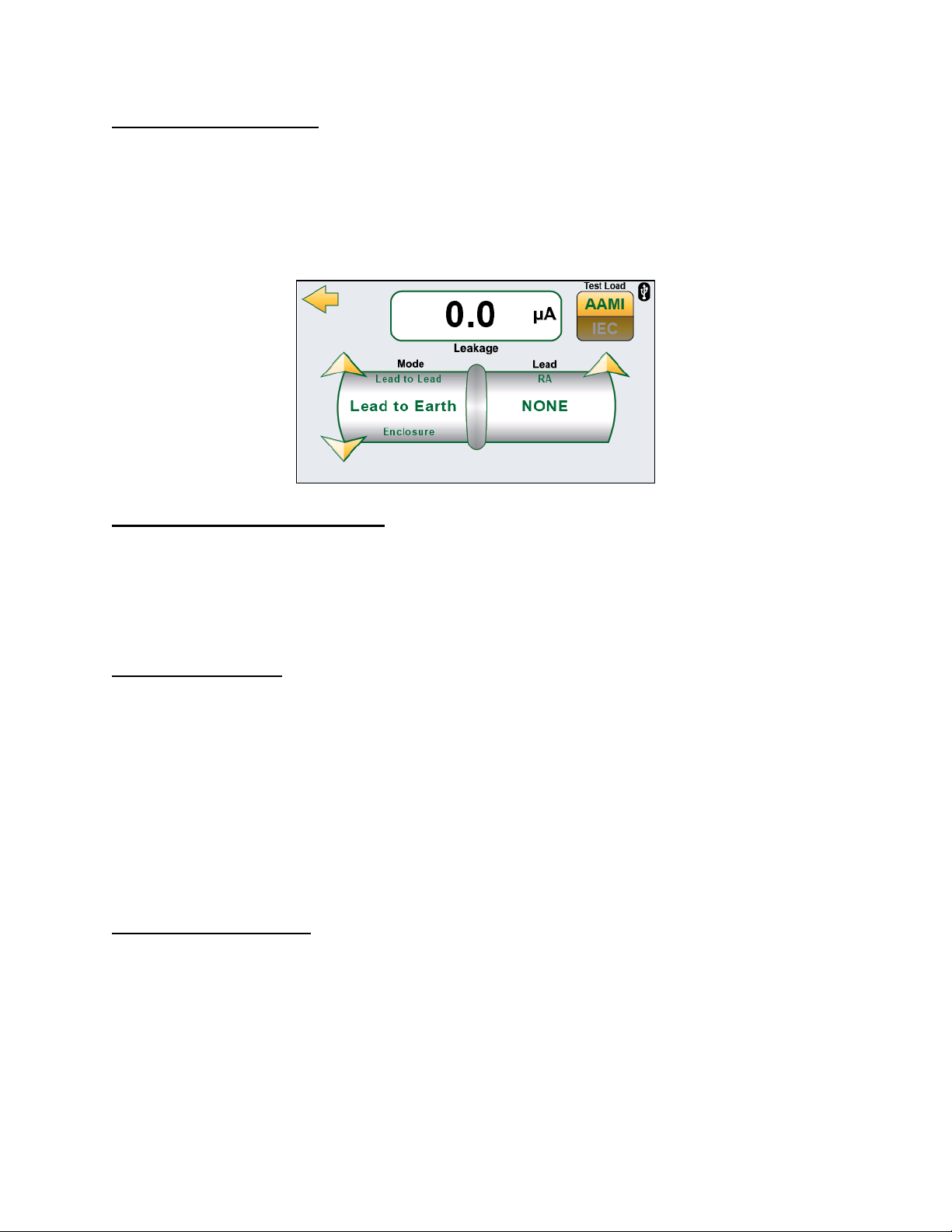
Leakage Modes Screen
The Leakage Modes Screen allows for multiple selectable leakage modes. The mode can
be changed by pressing the up/down arrows on the Mode side. If leads are valid for the
selected mode, they can also be changed with the up/down arrows on the Lead side. All
of the leakage modes will measure the current that flows through a 1000 Ω load with
either AAMI ES1-1993 or IEC 60601 frequency compensation as selected by the Test
Load switch.
Earth/Ground Leakage Current
In Earth/Ground Leakage Mode, the display will show the leakage current in the ground
wire of the DUT.
NOTE: This test has no meaning for equipment that does not use a grounded cord.
Enclosure Leakage
In Enclosure Leakage Mode, the display will show the leakage current between the
Enclosure (Chassis) and Earth/Ground.
The test requires that the Chassis Test lead be plugged into the Chassis Connector. The
other end should be connected to a solid ground point on the DUT.
NOTE: If a non-conductive enclosure is used, a 200 cm2conductive foil pad should be
used. This foil is to be placed in close contact with the enclosure and connected to the
Chassis Test lead.
Lead to Earth Leakage
In Lead to Earth Leakage Mode, the display will show the leakage current between the
selected lead and Earth/Ground.
Attach the patient leads to the connectors on the top of the Safety Analyzer. The Up and
Down arrow keys may then be used to select any individual lead or all the leads.
This test should be done for each lead individually and all leads together.
This test measures the leakage current that would flow through the leads if the patient
were to come into contact with Earth/Ground.
Table of contents
Other BC Group International Measuring Instrument manuals


