IWILL DNS-SATA User manual

IWILL
DNS-SATA/DNS/DNS-L
Motherboard
User’s Manual
Overview Hardware Installation BIOS Setup
FB25633100

DNS Motheroard IWILL
2 IWILL DNS Series

IWILL DNS Series 3
Disclaimer
The manufacturer makes no representations or warranties regarding the contents of this manual
and specifically disclaims any implied warranties of merchanta ility or fitness for any particular
purpose. Furthermore, the manufacturer reserves the right to revise this pu lication or make
changes in the specifications of the product descri ed within it at any time without notice and
without o ligation to notify any person of such revision or change.
Trademarks
Microsoft and Windows are registered trademarks of Microsoft Corp. Intel and Xeon are
registered trademarks of Intel Corporation. Other product names used in this manual are the
properties of their respective owners and are acknowledged.
Co yright
This pu lication, including all photographs, illustrations and software, is protected under
international copyright laws, with all rights reserved. Neither this manual, nor any of the material
contained here in, may e reproduced without the express written consent of the manufacturer.
IWILL ©Copyright 2004
All produce specs are subject to change without prior notice. The actual specs will be
according to the actual product.
IWILL User’s Manual
IWILL User’s Manual

DNS Motheroard IWILL
4 IWILL DNS Series
Table of Contents
Chapter 1 Overview.......................................................................................................... 6
DNS Package Content................................................................................................. 7
Safety Notice............................................................................................................... 8
Getting Help.............................................................................................................. 10
DNS Specifications....................................................................................................11
Chapter 2 ......................................................................................................................... 13
Components and Jumper etting .................................................................................. 13
Main oard Map......................................................................................................... 14
Components List ....................................................................................................... 15
Jumper Setting .......................................................................................................... 16
JP1: Clear CMOS Jumper................................................................................. 16
JP16: BIOS Protection Jumper ......................................................................... 17
JP20: VGA Jumper............................................................................................ 17
JP17; 21: FSB Jumper....................................................................................... 17
JP22 Chassis Intrusion Pin Header ................................................................... 18
J42 Case Open Pin Header................................................................................ 18
Rear Panel I/O Ports.................................................................................................. 19
Additional I/O Connectors........................................................................................ 21
J32: COM2 Header ........................................................................................... 21
J43: Front Panel Connector............................................................................... 21
J45: IrDA Connector ......................................................................................... 23
J92: IPMI connector.......................................................................................... 24
J105/ J106: LAN LED Header.......................................................................... 24
Serial ATA Connector................................................................................................ 25
USB Header .............................................................................................................. 25
DNS Power Supply................................................................................................... 27
IDE and Floppy Connectors...................................................................................... 28
Chapter 3 Hardware Installation .................................................................................. 30
Mother oard Installation........................................................................................... 31
Installing the CPU and Heatsink Procedures............................................................ 33
Heatsink Installation Notice...................................................................................... 37
Memory Installation Procedure................................................................................. 38
Installing Expansion Cards ....................................................................................... 41

IWILL DNS Series 5
PCI-Express Riser Card ............................................................................................ 42
Powering on your System ......................................................................................... 43
Chapter 4 BIO etup.................................................................................................... 44
BIOS Setup ............................................................................................................... 45
Using the BIOS Setup Utility ................................................................................... 47
Main Menu................................................................................................................ 49
Advanced Menu........................................................................................................ 50
Boot Menu ................................................................................................................ 51
Boot Setting Configuration Su menu....................................................................... 52
Exit Menu.................................................................................................................. 54
Chapter 5 ......................................................................................................................... 55
O and Drivers Installation ........................................................................................... 55
OS Installation .......................................................................................................... 56
Drivers Installation.................................................................................................... 57
IWILL User’s Manual
IWILL User’s Manual

DNS Motheroard IWILL
6 IWILL DNS Series
Chapter 1 Overview
Chapter 1 Overview

IWILL DNS Series 7
DN Package Content
1. DNS Mother oard
Professional server system oard
2. Three jumper caps
Extra caps in case original caps get lost
3. One Power Installation CD
Includes support software, drivers and undled software utilities.
4. Rear panel I/O shield
Covers the area around the rear panel I/O ports when the oard is installed in a
system housing.
5. One set of SATA ca les (DNS-SATA has two sets)
Connector ca le for on oard SATA connectors.
6. Two ATA-66/100 IDE ca les
Connects IDE devices to one of the on oard IDE connectors.
7. One floppy disk drive ca le
Connects floppy disk drives to the on oard floppy disk connector.
8. Two Hat Springs for CPU cooler
Sustain and connect etween CPU cooler and chassis
9. PCI-Express Riser Card
Change the PCI-Express slot from the vertical to horizontal direction. It is special
for 1U chassis.
10. Two CPU ackplates
It can fix the third party CPU heatsink. Please refer to Chapter 3 for detail
information.
11. Two heatsink retention modules
It can uckle up the CPU heatsink. Please refer to Chapter 3 for detail information.
IWILL Overview


IWILL DNS Series 9
When handling chips or modules, avoid touching their pins.
Put the mother oard and peripherals ack into their antistatic ags when not in use.
For grounding purposes, make sure your computer chassis provides excellent
conductivity etween the power supply, the case, the mounting fasteners and the
mother oard.
After accessing the inside of the system, close the system ack up and secure it to
the rack unit with the retention screws after ensuring that all connections have een
made.
OPERATING PRECAUTION
Check package contents
Missing or damaging accessories
Please contact your vendor immediately
Motherboard damage
Please contact your vendor immediately
Prepare minimum system components
Intel Xeon @800MHz FSB Processor
At least one Registered DDR memory module
At least one SATA or IDE HDD
EPS12V Power Supply with 460W or a ove
Important: You must have enough system integration knowledge before
the installation
IWILL Overview
IWILL Overview

DNS Motheroard IWILL
10 IWILL DNS Series
Getting Help
If a pro lem arises with your system during Installation or Operation, you should first ask
your dealer for help as they have most likely configured your system. They generally
have the est grasp of your issues and the fastest response for your symptoms. If your
dealer is near your location, it is recommended that you first ring your system to them to
have it serviced instead of attempting to solve the pro lem yourself.
If those options don't work for you, IWILL also provides some helpful resources to help
you.
1. Visit IWILL® we site at Http://www.iwill.net and navigate to this product’s page
which contain links to product updates such as Jumper settings or BIOS updates.
2. The FAQ (Frequently Asked Questions) sections in the IWILL we site are often
helpful since other users often have the same questions.
3. Email us at: support@iwill.net and we will try to answer your questions within 5
usiness days.

DN pecifications
Processor z Dual Intel® Xeon Socket 604 CPUs
z Supports 800MHz FSB
Chipset z Intel E7520 Chipset MCH
z Intel ICH5
z Intel PXH (DNS/DNS-SATA Only)
z Win ond 83627 HF
Memory z 8 DIMMs for 184-pin DDR 333/266 DIMM sockets
z Support up to 6 DIMMs DDR333 memory
z Support up to 8 DIMMs DDR266 memory
z Uses Registered DDR with ECC or Non-ECC memory
z Supports total system memory size of up to 16GB
On-Board LAN z Dual Broadcom PCI-Express G E Controller
z Two RJ-45 connectors for G E
z Support PME
Graphic z Integrated ATI RageXL video controller with 8MB memory
USB z 2 x external USB 2.0 ports at the rear panel
z 6 x internal USB 2.0 ports for the front panel
Serial ATA
z 8 Serial ATAII ports supported y Marvell with RAID 0, 1, 10
(DNS-SATA Only)
z 2 Serial ATA ports supported y ICH5
z Support hot swap
Expansion Slots
z One PCI Express x8 slot (for 1U)
z One PCI Express x8 slot (with x4 andwidth)
z One PCI-X 64- it/133 MHz (DNS/DNS-SATA Only)
z Two PCI-X 64- it/100 MHz (DNS/DNS-SATA Only)
Internal I/O
connector
z 1 x 34-pin Floppy Connector
IDE Bus
z 2x 40-pin IDE connectors, supports up to four (4) Enhanced IDE
devices
z Dual Channel Master Mode
z Ultra DMA 100/66/33
IWILL DNS Series 11
IWILL Overview

DNS Motheroard IWILL
12 IWILL DNS Series
Expansion I/O
z PS/2 mouse and key oard connectors
z 1 x UART 16550 serial port (COM1)
z 1 x internal UART y 9 pin header
z 2 x USB 2.0 ports
z 2 x Giga it Ethernet LAN RJ-45 port
z 1 x VGA port
System BIOS
z AMI BIOS
z Flash write protection y BIOS and one jumper
z Support Adaptec Host RAID
z LAN remote oot
z BIOS Boot specification v3.1 support
z Support ASF2.0
Server Management
z Support IPMI 1.5
z Support mBMC
z Support remote power on/off and reset support
System Management
z Hardware Monitor control y Analog Device ADM1026
z Fan speed control method: DC FAN
z Support AC power failure
Form Factor
z EATX form factor
z 12’’x13’’
z EEB 3.5
z EPS 12V power connectors (24 pin + 8 pin)

IWILL Components and Jumper Setting
IWILL DNS Series 13
Chapter 2
Components and Jumper etting

DNS Motheroard IWILL
14 IWILL DNS Series
Mainboard Map

IWILL DNS Series 15
Components List
CPU1; CPU2 Intel Xeon Socket604 Processor
Primary; Secondary IDE Driver Connectors
Floppy Floppy Disk Driver Connector
PCI Slots PCI-Express x8, x4 Slots; PCI-X 100,133
DIMM B4~A1 Memory Socket for DDR Memory
JP1 Clear CMOS Jumper
JP16 BIOS Protect Jumper
JP20 VGA Jumper
JP22 Chassis Intrusion Pin Header
JP17; 21 Memory Speed Jumper
J32 COM2 Port
J42 Case Open Pin Header
J43 Front Panel Connector
J45 IrDA Connector
J64, J65, J80, J81, J82, J83 Serial ATA Connector
J34, J90, J94 USB 2.0 Pin Header
J92 IPMI connector
J105, J106 LAN LED Pin Header
IWILL Components and jumper setting

DNS Motheroard IWILL
16 IWILL DNS Series
Jumper etting
JP1: Clear CMO Jumper
The on oard utton cell attery powers the CMOS RAM. It contains all the BIOS setup
information. Keep the jumper connected to pins 1-2 (Default) to retain the RTC data as
shown elow.
Under certain circumstances, you will need to reset system settings. Follow these
instructions to clear the CMOS RTC data:
1. Turn off the computer.
2. Short pins 2 and 3 with a jumper for a few seconds.
3. Replace the jumper to pins 1 and 2.
4. Turn on your computer y pressing the power-on utton.
5. Hold down <F2> during oot and select either <Load Optimal Defaults> or
<Load Failsafe Defaults> in the “Exit” section. Then go through the BIOS setup
to re-enter user preferences.
1-2 2-3
Normal (Default) Clear CMOS

IWILL DNS Series 17
JP16: BIO Protection Jumper
This jumper protects the system from unnecessary updating or flashing of the BIOS. It
secures the BIOS therefore prevents accidental overwriting of the data stored in flash
memory.
JP16
1-2 By Soft (Default)
2-3 Lock
Open Unlock
JP20: VGA Jumper
This header lets you set your VGA port function. You can choose ena le or disa le this
function or not.
JP17; 21: F B Jumper
This header lets you set your memory speed. Depend on the memory you choose, please
adjust this jumper in order to optimize your memory utilize.
1-2 2-3
VCC5 Stand By VCC5 (Default)
Setting J 17
LLSE0
J 21
LLSE1
Memory
in 1-2 Short(Default) Short(Default) DDR-333
in 2-3 short short DDR-266
IWILL Components and jumper setting

DNS Motheroard IWILL
18 IWILL DNS Series
JP22 Chassis Intrusion Pin Header
This feature uses a mechanical switch on the chassis that connects to the chassis intrusion
connector on the mother oard. When the chassis cover is removed the mother oard
circuitry will detect the intrusion.
J42 Case Open Pin Header
Case Open is a security function. This can detect whether the chassis (case) had een
opened or not. If the case had een opened, the open record would show on the screen
until you delete this message.
Setting J42
Pin 1-2 (default) Nothing
Pin 2-3 Intrusion
Setting J42
Open (default) Disa le
Close Ena le

IWILL DNS Series 19
Rear Panel I/O Ports
This is an illustration of the Main oard rear I/O port array
P /2 Mouse Connector (6-pin Female)
The system will direct IRQ12 to the PS/2 mouse if one is detected. If no mouse is
detected, IRQ12 will e free for expansion cards to use.
P /2 Keyboard Connector (6-pin Female)
This connection is for standard key oards using a PS/2 (mini DIN) plug. This connector
will not accept standard AT size (large DIN) key oard plugs. You may need a DIN to
mini DIN adapter for standard AT key oards.
U B Port Function
DNS provides the two USB 2.0 ports at the rear panel. USB 2.0 supports 480M /second
andwidth providing a marked improvement in device transfer speeds etween your
computer and a wide range of simultaneously accessi le external Plug and Play
peripherals. You can connect or disconnect USB ca les when the system is turned on.
Key oard
Mouse
USB 2.0
IWILL Components and jumper setting
Key oard
Mouse
USB 2.0

DNS Motheroard IWILL
20 IWILL DNS Series
erial Port Function
The serial ports are RS-232C asynchronous communication ports with
16C550A-compati le UARTs that can e used with modems, serial printers, remote
display terminals, and other serial devices. It can operate at speeds up to 115,200 ps. You
can configure the port’s speed in the computer’s Operating System.
VGA Port Function
The VGA port is for the image output. It can e used with the PC monitor devices.
LAN Port Function
The LAN port uses a CAT 5 LAN ca le for connecting the mother oard to a local area
network y means of a network hu . The port has 2 indicator LEDs.
Speed LED (left)
• 10M ps - will not link
• 100M ps - LED is green
• 1000M ps - LED is orange
Link and Activity LED (right)
• LED is yellow when the LAN connection is linked and accessed.
Serial COM VGA Port LAN 1 LAN 2
Other manuals for DNS-SATA
1
This manual suits for next models
2
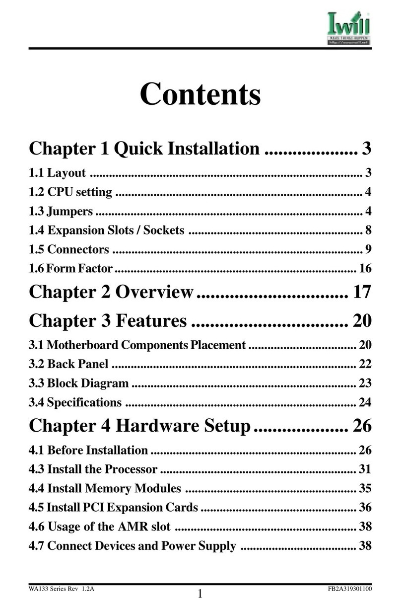
Table of contents
Other IWILL Motherboard manuals

IWILL
IWILL KK266 User manual

IWILL
IWILL FB24624100 User manual

IWILL
IWILL P55TV User manual

IWILL
IWILL P4G Series User manual

IWILL
IWILL XP333 User manual

IWILL
IWILL UPX User manual

IWILL
IWILL DP6NS User manual

IWILL
IWILL XA100 Ultra ATA-2 User manual

IWILL
IWILL PIINS User manual

IWILL
IWILL DN800-SLI User manual

IWILL
IWILL BD100 Plus User manual

IWILL
IWILL dca200 User manual

IWILL
IWILL WO2 Original operating instructions

IWILL
IWILL K7S3 Series User manual

IWILL
IWILL P4SP User manual

IWILL
IWILL P4SE Series User manual

IWILL
IWILL DP533 Series User manual

IWILL
IWILL IWILL P4D-N User manual

IWILL
IWILL KD266 User manual

IWILL
IWILL KK266Plus User manual