BCM FX815ELT User manual

BIOS Setup:
Getting Ready to Install OS from a Bootable OS Installation CD:
Step 1: Press <F2> key to enter the setup, it will get into Setup Menu.
Step 2: If doesn’t show up, press <CTRL>+<ALT>+<DEL> keys simultaneously and after the
system reboots, repeat Step 1.
Step 3: Select Restore tab by pressing the <→> key.
Step 4: Select Restore Default Settings by pressing the <↓> key.
Step 5: Press the <ENTER> key and new menu will appear.
Step 6: Select Restore Manufacturer Settings by pressing the <↓> key
Step 7: Press the <ENTER> key and new menu will appear.
Step 8 Press the <Y> key to change the default.
Step 9: Press the <ENTER> key and the menu disappears.
Step 10: Select General tab on the Main menu by using the <←> key.
Step 11: Press the <ENTER> key since the General Configuration is already selected.
Step 12: Select First Boot Device by using the <↓> key and press the <ENTER> key.
Step 13: New menu appears, select CDROM by using the <↓> key and press <ENTER> key to
accept.
Step 14: Press the <ESC> key to return to Main menu.
Step 15: Press the <ESC> key to move to Exit menu.
Step 16: Press the <ENTER> key since the Save CMOS & Exit is already selected.
Step 17: New menu appears, press the <ENTER> key to save and exit the setup. The
computer will reboot itself and will start seeking for the installation CD and boot from
there.
Getting Ready to Install OS or Run from a Bootable Floppy Disk:
Step 1: Press <DEL> key to enter the setup, it will get into Setup Menu.
Step 2: If doesn’t show up, press <CTRL>+<ALT>+<DEL> keys simultaneously and after the
system reboots, repeat Step 1.
Step 3: Select Restore tab by pressing the <→> key.
Step 4: Select Restore Default Settings by pressing the <↓> key.
Step 5: Press the <ENTER> key and new menu will appear.
Step 6: Select Restore Manufacturer Settings by pressing the <↓> key
Step 7: Press the <ENTER> key and new menu will appear.
Step 8 Press the <Y> key to change the default.
Step 9: Press the <ENTER> key and the menu disappears.
Step 10: Select General tab on the Main menu by using the <←> key.
Step 11: Press the <ENTER> key since the General Configuration is already selected.
Step 12: Select First Boot Device by using the <↓> key and press the <ENTER> key.
Step 13: New menu appears, select FLOPPY by using the <↑> key and press <ENTER> key to
accept.
Step 14: Press the <ESC> key to return to Main menu.
Step 15: Press the <ESC> key to move to Exit menu.
Step 16: Press the <ENTER> key since the Save CMOS & Exit is already selected.
Step 17: New menu appears, press the <ENTER> key to save and exit the setup. The
computer will reboot itself and will start seeking for the installation floppy disk and boot
from there.
Getting Ready to Install OS or Run the OS from a Hard Disk Drive:
Step 1: Press <DEL> key to enter the setup, it will get into Setup Menu.
Step 2: If doesn’t show up, press <CTRL>+<ALT>+<DEL> keys simultaneously and after the
system reboots, repeat Step 1.
Step 3: Select Restore tab by pressing the <→> key.
Step 4: Select Restore Default Settings by pressing the <↓> key.
Step 5: Press the <ENTER> key and new menu will appear.
Step 6: Select Restore Manufacturer Settings by pressing the <↓> key
Step 7: Press the <ENTER> key and new menu will appear.
Step 8 Press the <Y> key to change the default.
Step 9: Press the <ENTER> key and the menu disappears.
Step 8: Press the <ESC> key to move to Exit menu.
Step 9: Press the <ENTER> key since the Save CMOS & Exit is already selected.
Step 10: New menu appears, press the <ENTER> key to save and exit the setup. The
computer will reboot itself and will start seeking for the hard disk drive and boot from
there.
FX815ELT
FX815ELT
For Intel Pentium III/ Tualatin and Celeron Processors
User’s Quick Start Card Version 1.0 http://www.bcmcom.com
Inspect the Package:
One FX815ELT Motherboard
One IDE Cable (80 Pins)
One Floppy Cable
One Driver CD
One User’s Quick Start Card
One COM2 Cable
One TV Out Cable
One Front USB and Firewire cable (Option)
Responsibility:
This manual is provided “As-Is” with no warranties of any kind, either expressed or implied,
including, but not limited to the implied warranties or conditions of this product’s fitness for
any particular purpose. In no event shall we be liable for any loss of profits, loss of
business, loss of data, interruption of business, or indirect, special, incidental, or
consequential damages of any kind, even the possibility of such damages arising from any
defect or error in this manual or product. We reserve the right to modify and update the
user manual without prior notice.
WARNING: CMOS Battery Damage
Replace your system’s CMOS RAM battery only with the identical CR-2032 3V Lithium-Ion
coin cell (or equivalent) battery type to avoid risk of personal injury or physical damage to
your equipment. Always dispose of used batteries according to the manufacturer’s
instructions, or as required by the local ordinance (where applicable). The damage due to
not following this warning will void your motherboard’s manufacturer warranty.
Additional Information:
Additional information on setting this board up can be found in the User’s Manual in the
provided CD-ROM. The Online User’s Manual and FAQ/Knowledge Base can be found on
our website by visiting our website: http://www.bcmcom.com. If your question is not
answered in our FAQ/Knowledge Base, visit our forums and post your messages or submit
a new FAQ through FAQ Submittal form for us to add your question in our FAQ with our
answer.
ATTENTION: Incorrect BIOS Setup
If you do not know how to handle BIOS setup or how to set it up properly, it is strongly
advisable that you do not modify any of the settings than otherwise instructed in the User’s
Quick Start Card. Even a seemingly small incorrect adjustment or modification in the BIOS
setup can render your system unstable or unusable. The incorrect BIOS setup is not
covered by your motherboard’s manufacturer warranty.
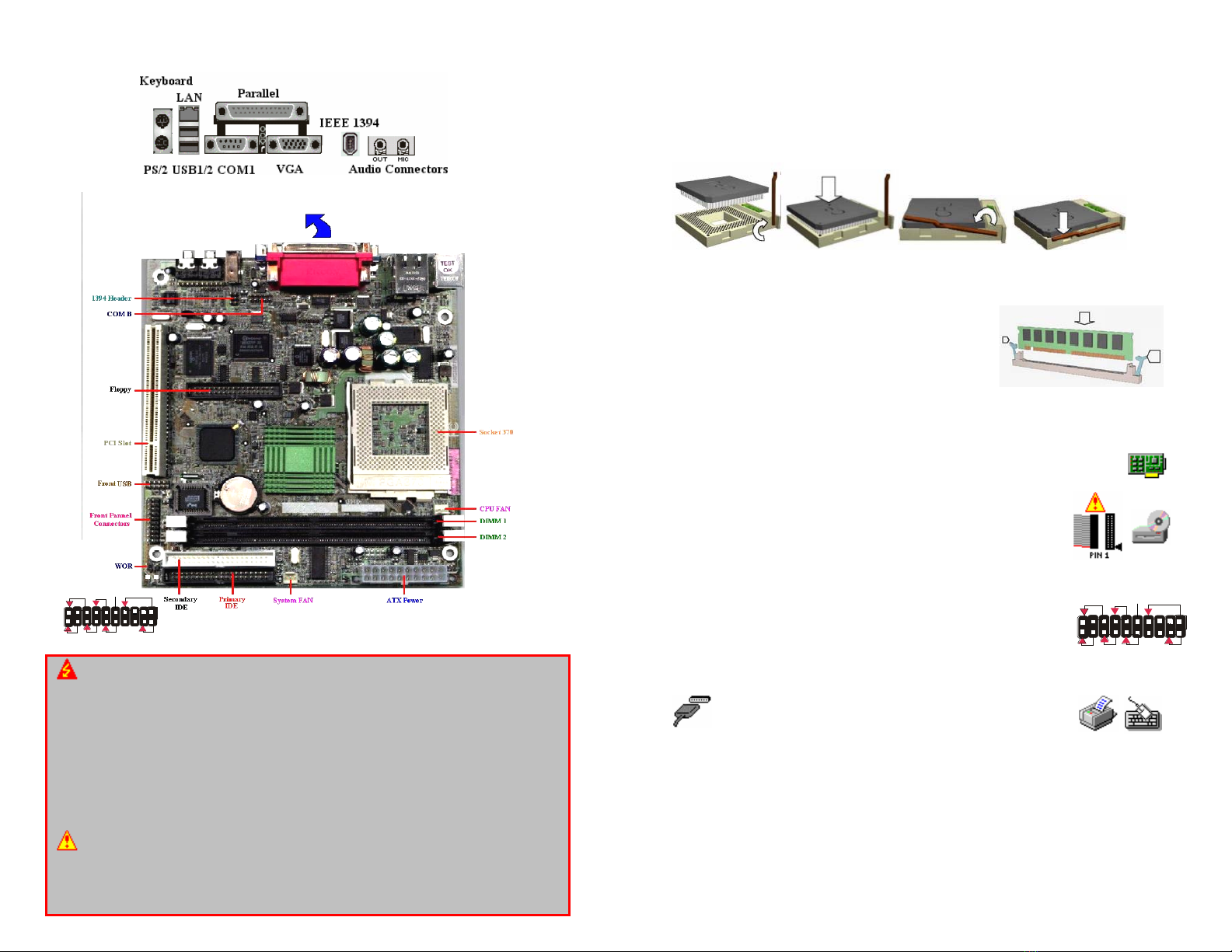
Motherboard Layout:
WARNING: Electrostatic Sensitive Device (ESD)
Static electricity can easily damage your motherboard and will void your motherboard
warranty. Keep the motherboard and other system components in their anti-static
packaging until you are ready to install them. Touch a grounded surface before you
remove any system component from its protective anti-static packaging. Unpacking and
installation should be done on a grounded, anti-static mat. The operator should be wearing
an anti-static wristband, grounded at the same points as the anti-static mat. During
configuration and installation touch a grounded surface frequently to discharge any static
electrical charge that may have built up in your body. Avoid touching the components
when handling the motherboard or a peripheral card. Handle the motherboard and
peripheral cards either by the edges or by the peripheral card case-mounting bracket.
WARNING: Misplaced Jumper Damage
Incorrect setting jumpers and connectors may lead to damage to your motherboard and will
void your motherboard warranty. Please pay special attention not to connect these
headers in wrong directions. DO NOT change ANY jumpers while the motherboard has the
power!
HDD LED
RESET
PWR/SLEEP
PWR
KEY
IrDA
SMBUS
SPK
HDD LED
RESET
PWR/SLEEP
PWR
KEY
IrDA
SMBUS
SPK
Install a CPU:
Please follow the below steps to install your CPU in SOCKET 370.
Step 1: Pull the handling bar of the socket upward to the other end to loosen the socket’s
openings.
Step 2: Place the CPU on the middle of the socket, orienting its beveled corner to line up
with the socket’s beveled corner. Make sure the pins of the CPU fit evenly to the
socket openings.
Step 3: Press the handling bar downward to fasten the CPU to the socket.
Step 4: Install the CPU heatsink with some thermal jelly on the CPU and secure the
brackets.
Install a DIMM:
Step1: Make sure Pin 1 of the DIMM match with pin 1
of the DIMM 1, and DIMM 2 sockets.
Step2: Insert the DIMM module into the DIMM socket
vertically. After inserting the DIMM module
completely into the socket, push up on the
socket latches securing the DIMM into place.
If the pin 1 of the DIMM module does not line
up with pin 1 of the socket, the DIMM module will not be inserted correctly into
the socket.
Install a Peripheral Card:
To install expansion cards, please read the expansion card’s documentation for
instructions or cautions prior to the installation.
Install the Drives:
Install the floppy drive cable to FLOPPY, the hard disk drive cable to
PRIMARY IDE, the CD-ROM, DVD-ROM, CD-R, or CD-RW cable to
SECONDARY IDE. NOTE: Colors on the IDE ports may vary.
Plugging-In the ATX Power Supply Connector:
Plug the ATX Power Supply cable to ATX POWER.
Plugging-In the Front Panel Connectors:
Plug in each cable to their assigned headers as labeled on the
connectors (FRONT PANEL CONNECTORS) and the figure on the right.
If the light does not lit up, simply reverse the polarity. The colored wires
of each connector usually denote a positive lead, which aligns with red
arrows as illustrated on the right.
Plugging-In the Back Panel Ports:
Plug in Keyboard, Mouse, USB, Serial 1 (COM1), LAN, Video
and Parallel (printer) ports. Please refer to the figure on the
Motherboard Layout page.
Jumpers:
The BIOS handles all of the configurations including FSB speed, and CPU multiplier.
Other Connectors:
CPU fan connector needs to be connected to the CPU FAN if the heatsink is equipped with
one. System fan connector needs to be connected to the SYS FAN if the system is
equipped with one.
Other BCM Motherboard manuals


