6
1INSTALLATION
1.1 Installation Preparation
Basic Requirement
zAll installation and operation here should conform to your local electrical safety
codes.
zBefore installation, please open the package and check all the components are
included. Please make sure the speed dome installation environment and
installation mode can meet your requirement. If there is special requirement,
please contact your local retailer for more information.
zWe assume no liability or responsibility for all the fires or electrical shock caused
by improper handling or installation.
Check installation space and installation location intension
Please make sure the installation environment has enough space to install the speed
dome and its corresponding bracket.
Please make sure the ceiling, wall, bracket can support the speed dome and its
corresponding installation component. The safety factor shall be 4X.
About cable
Please select the cable according to your transmission distance.
The minimum video coaxial-cable requirement is:
z75 ohm.
zFull cable with copper conductor
z95% knitted copper shield
International Model Max Distance
(Ft\M)
RG59/U 750ft (229m)
RG6/U 1,000ft (305m)
RG11/U 1,500ft (457m)
Set dial switch button
Set dial switch button according to control protocol and speed dome address.
(Please refer to user’s manual for detailed information.)
Please keep all package material well for future use
Please keep speed dome package material well in case you need to send it back to
your local retailer or manufacturer for maintenance work.
Non-original package material may result in device damage during the transportation.
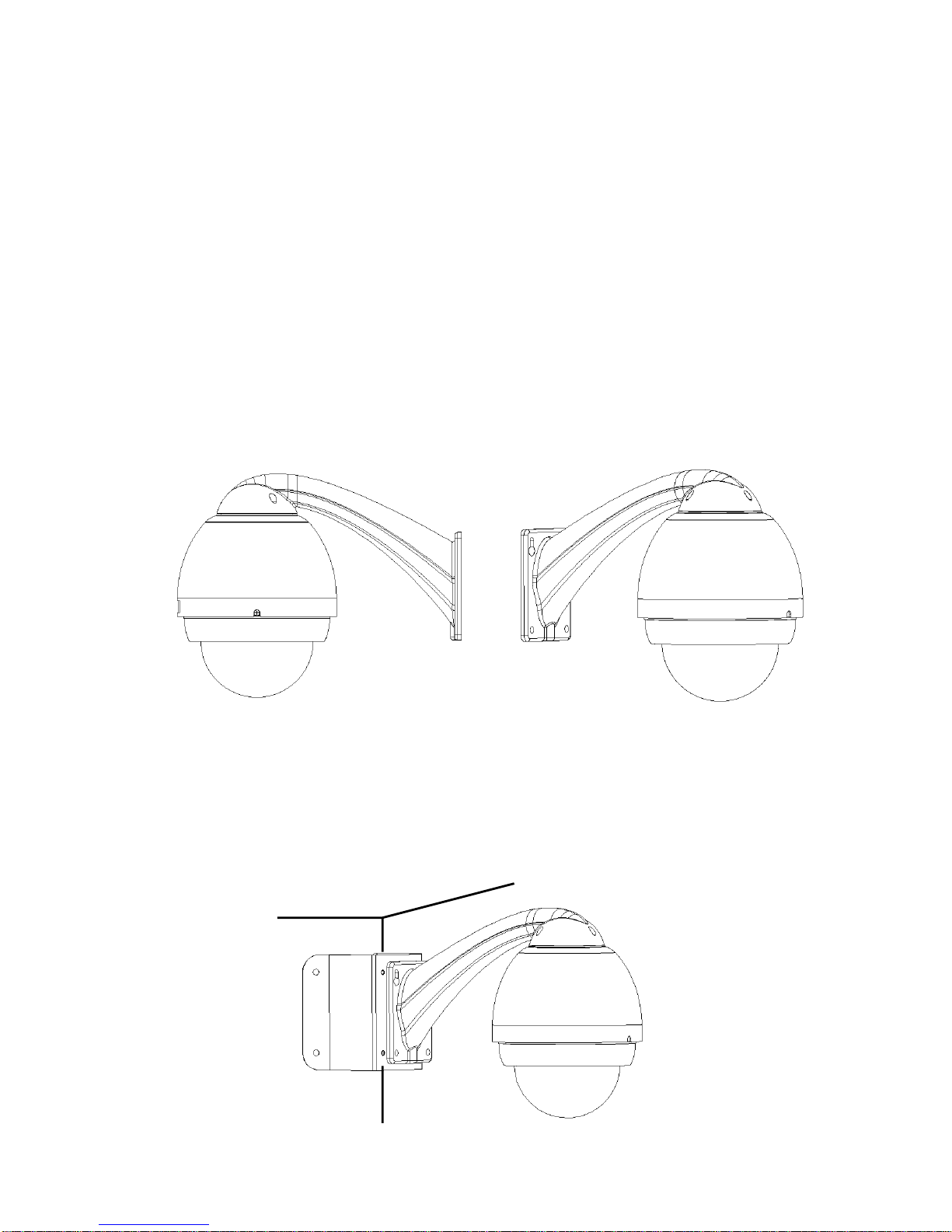
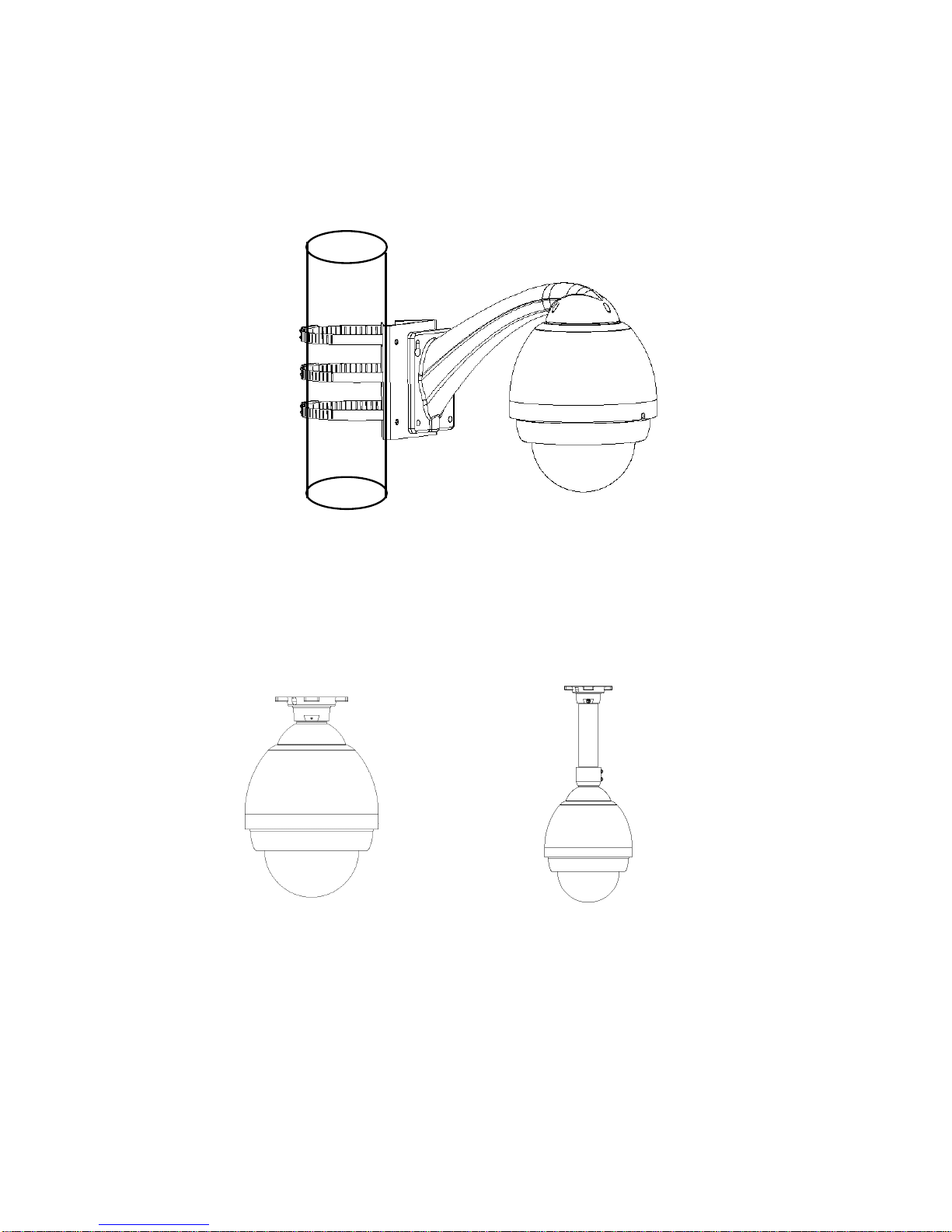
1.2 Installation Mode
1.2.1 Speed Dome Installation Mode
The integrated speed dome has the following installation modes: