BDS 740SPLWF User manual
SOLAR POWERED LIGHTED WINDSOCK FRAME
Model 740SPLWF, 740SPCU-1220 or 740SPCU-3555
NO SCALE
DATE
DATE
DRAWN
APPD
REV
1/8/06
4/18/20
KLB
RBB
LIGHTED WINDSOCKS
INSTALLATION (Mech/Elect)
www.LightedWindsocks.com
READ ALL INSTRUCTION BEFORE ATTEMPTING INSTALLATION
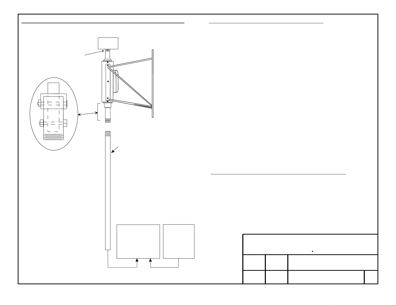
3 conductor cable
Two bolts and nuts
provided
Eight (8) foot 1" (ID) Sch 40
mounting pipe supplied
"By Others" for mounting
Two feet left for supporting
pole (approximately).
Solar powered
top beacon
See notes
The pipe extending
above the frame is for
the installation of a top
beacon when ordered
1. The wiring to the Solar Panel and Control Unit is always installed in the windsock
frame support pipe.
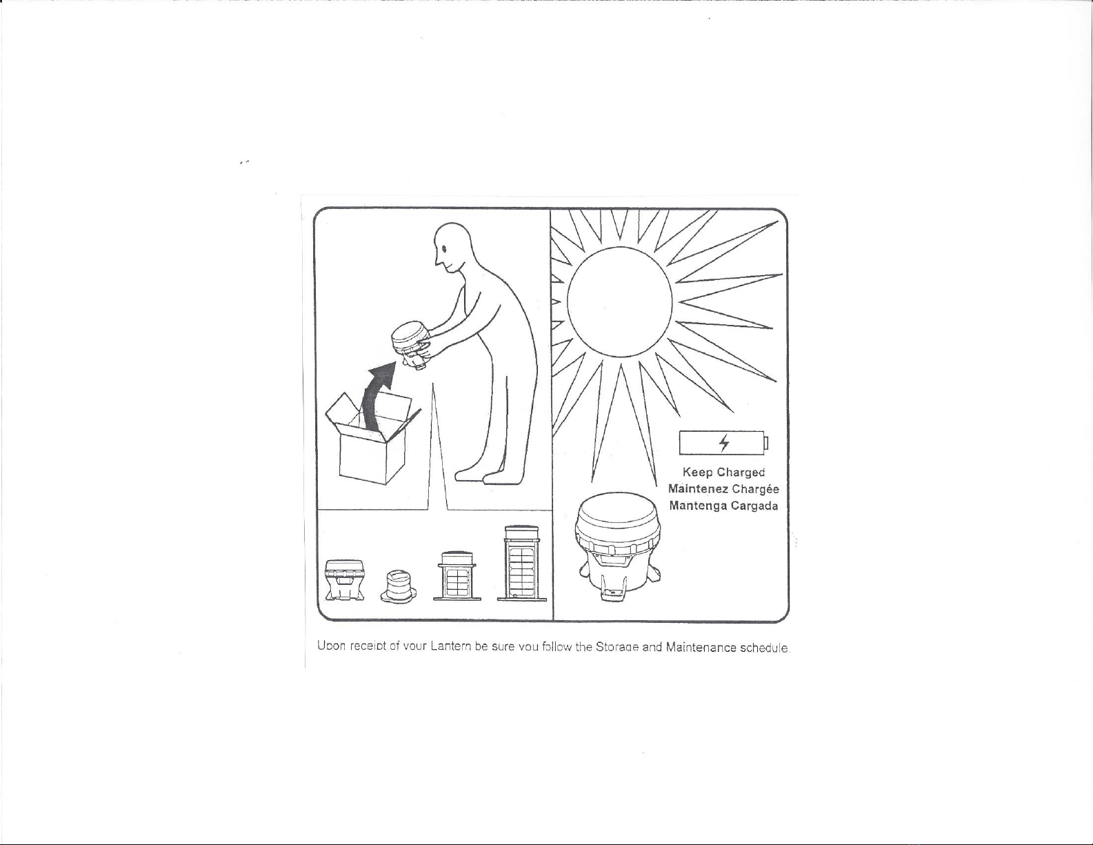
The Model 740SPLWF-CTB lighted windsock frame is supplied with a solar
powered top beacon and does not require any external power. This item is only
supplied when ordered as a Model 740SPLWF-CTB. Consult factory for details.
2. Install the mounting pile and Control Unit as shown.
3. Connect the wires coming from the LED light assembly to the connection
terminals marked "load". Black wire ground or negative (-), red wires positive (+).
Note: If a third wire (white) is supplied coming from the Windsock this wire is
for changing the lights flash patterns. This wire is normally OPEN
and only momentarily connected to +12VDC power to change the flash pattern/s.
See attached data sheet for details. Consult factory.
4. All wires must enter the bottom of the Control Unit through the supplied
compression fitting. Tighten fitting after wiring is complete.
5. Check all wiring is correct and secure before securing Control Units cover.
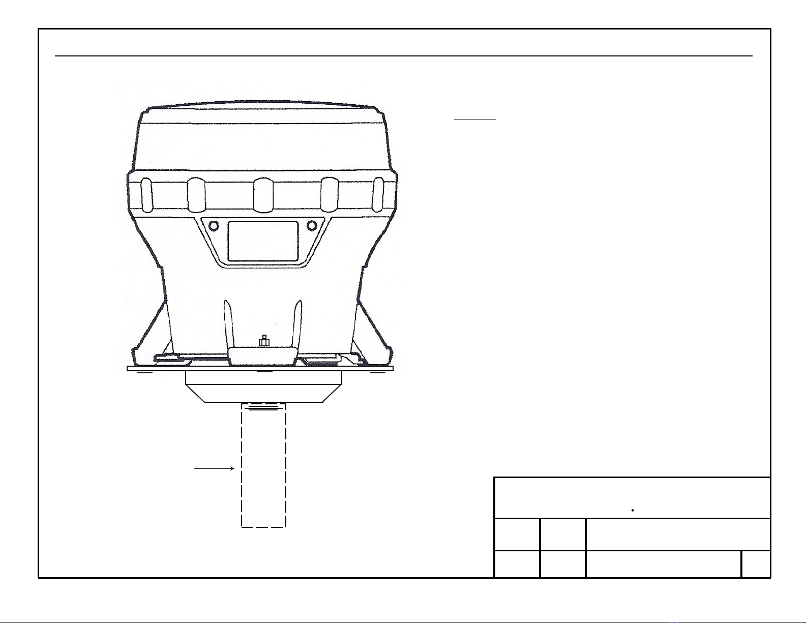
FRAME INSTALLATION GUIDE - TOP BEACON
Windsock in a limp position
(no wind) hangs down from
frame approximately...
C421IO (18"x5'x8") 33 inches
C422IO (18"x8'x 8") 66 inches
Wires from windsock frame
to Control Unit approximately
12 feet
Changing Windsock Flash Patterns - Multi patterns available
1. With LED's active connect white flash pattern wire to +12 volts for
more than 1 second will cause the lighthead to cycle through the
flash patterns. When the desired pattern is displayed, allow it to
run for more than 5 second. This pattern is selected.
This feature is not available for all windsock LED lights or top beacons.
Customer may connect a 1" or
larger mounting pipe below
pipe supplied using the proper
coupling.
Control Unit
with
Sunlight Controller
and
Battery
Solar Panel
with
Mounting
Brackets
2 conductor cable
Two bolts and nuts
provided. Do not remove.
Eight (8) foot 1" (ID) Sch 40
mounting pipe supplied
"By Others" for mounting
Top Beacon
AC Powered
Windsock in a limp position
(no wind) hangs down from
frame approximately...
W185-IO (18"x5'x8") 45 inches
W188-IO (18"x8'x8") 80 inches
Wires from windsock frame
to Control Unit 12 feet
(approximately).
Customer may connect a 1" or
larger mounting pipe below
pipe supplied using the proper
coupling.
3 conductor cable
SP Control Unit
with
Sunlight Controller
and
Battery Pack
Solar Panel
with
Mounting
Brackets
2 conductor cable
939 NATHANIEL TRAIL WARWICK, PA 18974
BDS SYSTEMS INC.
939 NATHANIEL TRAIL WARWICK, PA 18974
BDS SYSTEMS INC.
939 NATHANIEL TRAIL WARWICK, PA 18974
BDS SYSTEMS INC.
939 NATHANIEL TRAIL WARWICK, PA 18974
BDS SYSTEMS INC.
939 NATHANIEL TRAIL WARWICK, PA 18974
BDS SYSTEMS INC.
939 NATHANIEL TRAIL WARWICK, PA 18974
BDS SYSTEMS INC.
The pipe extending
above the frame is for
the installation of a top
beacon when ordered
Solar powered
top beacon
See notes

SOLAR POWERED LIGHTED WINDSOCK FRAME
Model 740SPLWF
NO SCALE
DATE
DATE
DRAWN
APPD
REV
BDS
SYSTEMS INC.
756 SANDY RIDGE ROAD DOYLESTOWN, PA 18901
9/15/08
4/18/20
KLB
RBB
LIGHTED WINDSOCKS
INSTALLATION (Electrical)
www.LightedWindsocks.com
FRAME INSTALLATION GUIDE
SOLAR POWERED CONTROL UNIT
Model 740SPCU
Solar Panel
with
Mounting Bracket
SP Control Unit,
Sunlight Controller,
and Battery
READ ALL INSTRUCTION BEFORE ATTEMPTING INSTALLATION
2 conductor cable
approx 5 feet long
3 conductor cable
approx 10 feet long
Solar Bat. Load
+ + +
- --
1. The solar panel surface must not be damaged. Do not damage any part of the solar
panel as a damaged solar panel will not operate properly.
2. Install the solar panel using the straps or U-bolts provided. For best charging
installation, the solar panel should face in a true South direction (In northern latitudes),
or true North (in southern latitudes) - towards the sun. Adjust the panels direction and
tile for best charging operation. Check with local authorities for complete information.
Solar panel mechanical installation attached.
3. Install the Control Unit using the manufactures mounting tabs and as close as
possible to the solar panel. All writing must enter the bottom of the Control Unit
through the compression fitting. Inspect mounting of solar panel and Control Unit.
4. Connect wiring inside the Control Unit as follows:
(a) First connect the battery to the proper terminals on the SL-10 Solar Controller.
(Plus wire to + terminal of battery, negative wire to - terminal of battery)
(b) Next connect the solar panel to the proper terminal on the Solar Controller.
(Red wire to fuse wire that is connected to terminal marked +, black wire to terminal
marked -). Fuse 3 amps optional.
(c) Last connect the light (load) to the proper terminals on the Solar Controller.
(Red wire to the terminal marked +, black wire to the terminal marked -).
5. BDS has set the On/Off time in the Control Unit as follows: ON at sunset, OFF at
sunrise. (The ”D/D” setting is dusk to dawn). See attached data sheet (Light Settings)
for other settings.
6. BDS has set the LED light assembly for Steady Burn - On continuously. Other
flash patterns are available. See attached data sheet (Light Settings) for other settings.
7. During installation or service do not leave the cover/door open or unprotected.
Secure all loose items and inspect when complete.
8. A third wire (white) is provide from the LED light assembly for changing the flash
patterns. Momentarily connecting this white wire to +12 volts will change the flash
pattern. Do not leave this wire connected. See attached data sheet (Light Settings) for
other settings. Consult factory.
9. Top extension above the windsock frame is for a solar powered top beacon when
ordered. Consult factory.
939 NATHANIEL TRAIL WARWICK, PA 18974
BDS SYSTEMS INC.
Top Beacon
AC Powered
939 NATHANIEL TRAIL WARWICK, PA 18974
BDS SYSTEMS INC.
Solar powered
top beacon
See notes
A
939 NATHANIEL TRAIL WARWICK, PA 18974
BDS SYSTEMS INC.
939 NATHANIEL TRAIL WARWICK, PA 18974
BDS SYSTEMS INC.
939 NATHANIEL TRAIL WARWICK, PA 18974
BDS SYSTEMS INC.
BDS 740SPLWF – Solar Powered Systems - Light Settings (continued)
740SPCU-1220 or 740SPCU-3555 (Solar Powered Control Unit)
Field Selectable ON and OFF Settings
The controller maybe field set to ten (10) different lighting control settings when power is applied to the LED light
assembly. Applying power to the lights for a shorter time will conserve battery power. The different control settings are:
SETTINGS LED's LIGHT OPERATION
OFF DAY=OFF Sunset = OFF Sunrise = OFF (Lights are always OFF)
2 Day =OFF Sunset = ON for 2 Hrs Then OFF
4 DAY=OFF Sunset = ON for 4 Hrs Then OFF
6 DAY=OFF Sunset = ON for 6 Hrs Then OFF
8 DAY=OFF Sunset = ON for 8 Hrs Then OFF
10 DAY=OFF Sunset = ON for 10 Hrs Then OFF
3/1 DAY=OFF Sunset = ON for 3 Hrs Then OFF, Then ON 1 Hr. before Sunrise
4/2 DAY=OFF Sunset = ON for 4 Hrs Then OFF, Then ON 2 Hrs. before Sunrise
6/2 DAY=OFF Sunset = ON for 6 Hrs Then OFF, Then ON 2 Hrs. before Sunrise
D/D DAY=OFF Sunset = ON Sunrise = OFF (ON dusk to dawn). BDS default setting.
Some top beacons are shipped loose and not attached to the lighted windsocks frames support pipe. If this is the case
install the top beacon as follows:
1. The 740SPLWF-CTB is supplied with a threaded mounting base plate. Thread this base plate on to the lighted
windsocks support pipe. Check that the unit is tight and secure. See instruction shipped with the unit.
740SPLWF-CTB
This top beacon has many different flash patterns. BDS supplied this unit with Red LED’s, clear lens, ON/OFF switch and
a steady burn flash code of 001. Other flash patterns (codes) can be field set. The battery can be field replaced. Consult
factory for other info.

BDS 740SPLWF – Solar Powered Systems - Light Settings
740SPLWF (Solar Powered Lighted Windsock Frame) Field Programmable Flash Patterns
Fifteen (15) different patterns are available. These flash patterns are as follows:
1. Steady burn. Lights ON continuously when power is supplied. BDS default setting.
2. SignalAlert™ - 75fpm and 150fpm - preceded with a microburst flash followed by a specified
a. 75fpm, 325ms ON time/OFF time
b. 150fpm, 200ms ON-time/OFF time.
3. SingleFlash - 375fpm, 150fpm, 75fpm and 15fpm - single flash patterns.
a. 375 is ON for 80ms, OFF for 80ms in a repeated pattern.
b. 150 is ON for 200ms, OFF for 200ms in a repeated pattern.
c. 75 is ON for 500ms, OFF for 300ms in a repeated pattern.
d. 15 is ON for 2 seconds, OFF for 2 seconds (50% duty cycle) in a repeated pattern.
4. DoubleFlash - 150fpm and 75fpm - double flash burst
a. 150fpm followed by an OFF time (150-400ms,).
b. 75fpm followed by an OFF time (75-350ms).
5. CometFlash® - a burst of 4 light impulses, followed by an OFF time of 350ms.
6. ActionFlash™ - a pattern that repeats a mix of two CometFlash® burst followed by 4 SingleFlash patterns.
7. ModuFlash™ - a sweeping (rising and falling effect) pattern of increasing intensity followed by decreasing intensity.
8. ComAlert™ - a pattern that mixes a combination of CometFlash® and SignalAlert™ for a unique warning pattern.
9. ActionScan™ - scans through all of the above patterns (except steady burn) separated by a series of single
flashes.
10.SignalAlert™ - Steady Burn pattern preceded with a SignalAlert™ micro burst flash.
NO SCALE
DATE
DATE
DRAWN
APPD
REV
1/20/09
4/18/20
KLB
RBB
LIGHTED WINDSOCKS
INSTALLATION (Mech)
www.LightedWindsocks.com
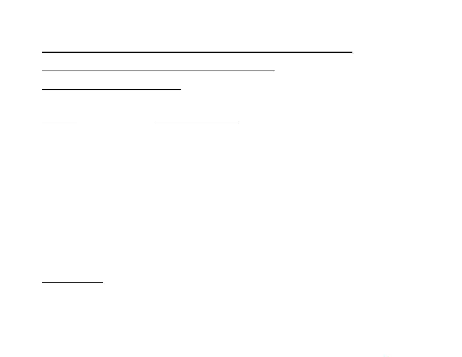
LIGHTED WINDSOCK FRAME - Pipe Connection
Mounting Hardware
NOTES
1. The above is a guide for installing a BDS lighted windsock frame assembly. The installer must
decide whether to use a 1” or larger support pipe for the installation. Everything below the
shown pipe connect must be supplied “By Others”.
2. The wiring cable that supplies power to the windsock frame and top beacon when ordered is
not shown in this drawing. Support for the bottom support pipe is “By Others”.
3. The BDS supplied 1” (ID) threaded connection has a 1.315 nominal outside diameter.
4. Galvanized schedule 40 pipe available at any good plumbing supply house.
5. Suggest using a Antiseize lubrication or lubrication tape around piping threads prior to
assembly for corrosion prevention and easy assembly and disassembly if necessary.
Windsock frame
1” (ID) mounting
pipe connection.
Supplied by
BDS Systems.
1” coupling
supplied by
BDS Systems
1 ½ ” X 1” reducer
coupling shown.
Supplied
“By Others”
1 ½” support pipe
supplied
“By Others”
1” support pipe
supplied
“By Others”
Using a coupling
Using a reducer
939 NATHANIEL TRAIL WARWICK, PA 18974
BDS SYSTEMS INC.
B
939 NATHANIEL TRAIL WARWICK, PA 18974
BDS SYSTEMS INC.

BDS WINDSOCK FRAME ASSEMBLY
DATE
DATE
DRAWN
APPD
REV
10/10/11
4/18/20
KLB
RBB
Windsock frame assembly
www.LightedWindsocks.com
Specifications subject to change without notice
939 NATHANIEL TRAIL WARWICK, PA 18974
BDS SYSTEMS INC.
Galvanized pipe
connection*
Stainless steel
tubing*
Windsock frame
4 x 4 PVC tubing **
SS clamp
(optional)*
Rubber
rain seal
washer
(optional)*
Delrin bottom
bearing** Delrin top
bearing**
Delrin rain
Cap*
Delrin bottom
support bearing*
Notes
1. Windsock frame support rods and windsock mounting ring not shown.
2. Miscellaneous screws / bolts not labeled. All parts not shown.
3. Center support tubing shown separately and with parts assembly.
4. Items with single asterisk (*) are stationary and do not move.
5. Items with double asterisk (**) rotate with the direction of the wind.
6. Electronics inside the tubing and LED light assembly not shown.
7. All Delrin parts white. All SS parts 304 stainless unless noted.
(Exploded parts view)
NO SCALE
NO SCALE
DATE
DATE
DRAWN
APPD
REV
1/8/06
4/18/20
KLB
RBB
SOLAR POWERED
LIGHTED WINDSOCKS
www.LightedWindsocks.com
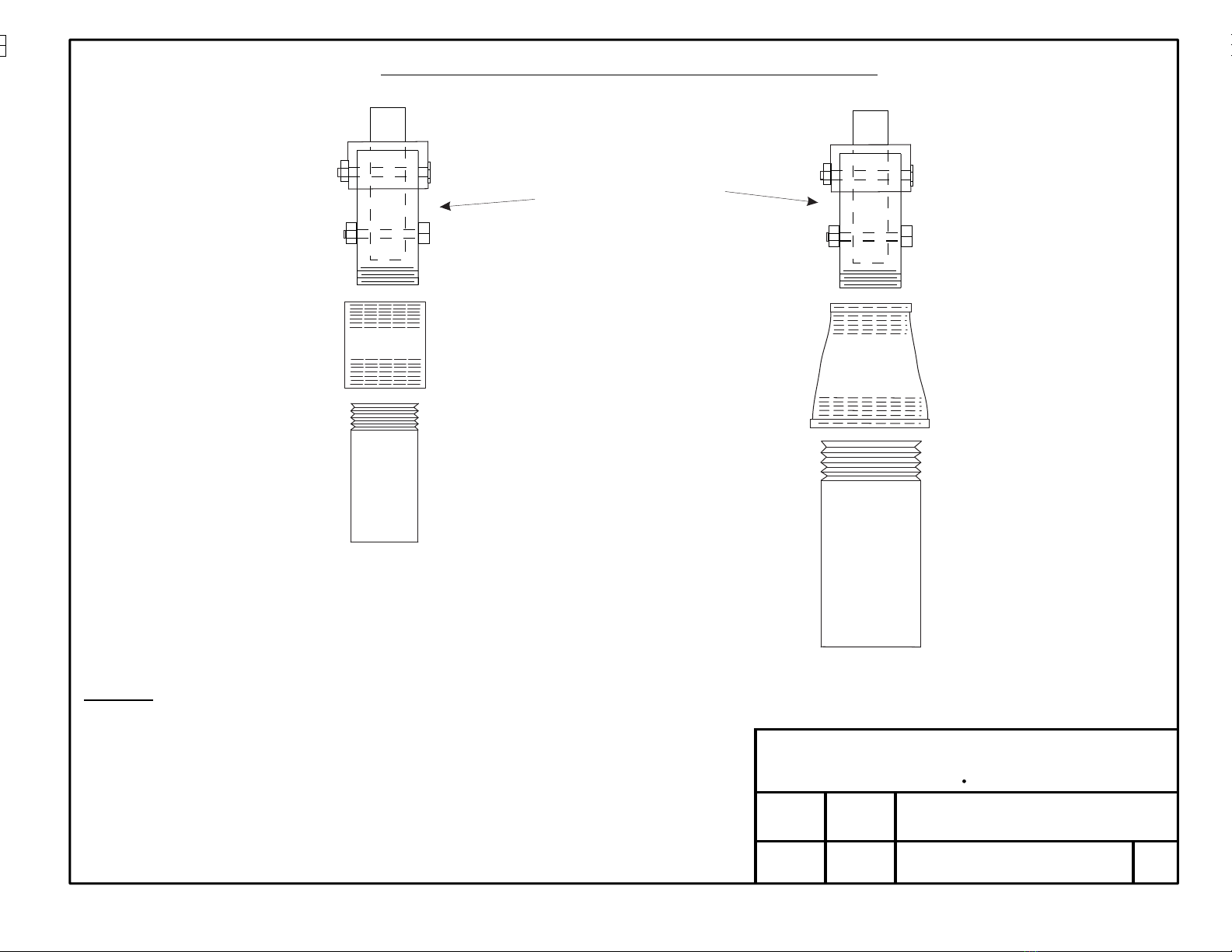
SOLAR PANEL MOUNTING MECHANICAL INSTALLATION
1/4 - 20 x 1" HEX SCREW
1/4" SPLIT LOCKWASHER
1/4" FLAT WASHER
(4 each)
ARM
CLAMPS
1. Study all drawings and be comfortable with installation before proceeding.
2. Mount saddle bracket to pole with two adjustable pipe band clamps, Feed thru slots in bracket. Mount bracket with "Nutsert" facing "UP".
Mounting saddle will adjust to a 1" to 3 1/2" pipe. Make sure saddle is secure and facing in correct charging direction.
3. Lay solar panel face down on a clean, soft, flat surface for mounting adjustable arm.
4. Assemble two clamps to arm assembly as shown. Do not tighten.
5. Position arm assembly over center of solar panel pushing bottom clamps all the way down into frame and loosely tighten bottom clamp.
6. Next push upper clamp into top of frame and loosely tighten. Inspect arm assembly is straight and then tighten all screws. Power cable
from solar junction box should be facing down as shown on drawing.
7. Attach arm assembly to saddle bracket as shown using four (4) screws (2 each side) with lockwashers and flat washers.
8. Tilt solar panel assembly for best charging angle them tighten all screws and inspect.
NOTES
Solar
Junction
Box
Solar
Panel
(Back side)
SOLAR PANEL MOUNTED TO PIPE
with two adjustable pipe band clamps
Adjustable tilt for best charging
Standard is a 45 degree angle.
(Holes 15 degrees apart)
939 NATHANIEL TRAIL WARWICK, PA 18974
BDS SYSTEMS INC.
939 NATHANIEL TRAIL WARWICK, PA 18974
BDS SYSTEMS INC.
939 NATHANIEL TRAIL WARWICK, PA 18974
BDS SYSTEMS INC.
939 NATHANIEL TRAIL WARWICK, PA 18974
BDS SYSTEMS INC.
939 NATHANIEL TRAIL WARWICK, PA 18974
BDS SYSTEMS INC.
NO SCALE
DATE
DATE
DRAWN
APPD
REV
KLB
RBB 04/18/20
6/1/14
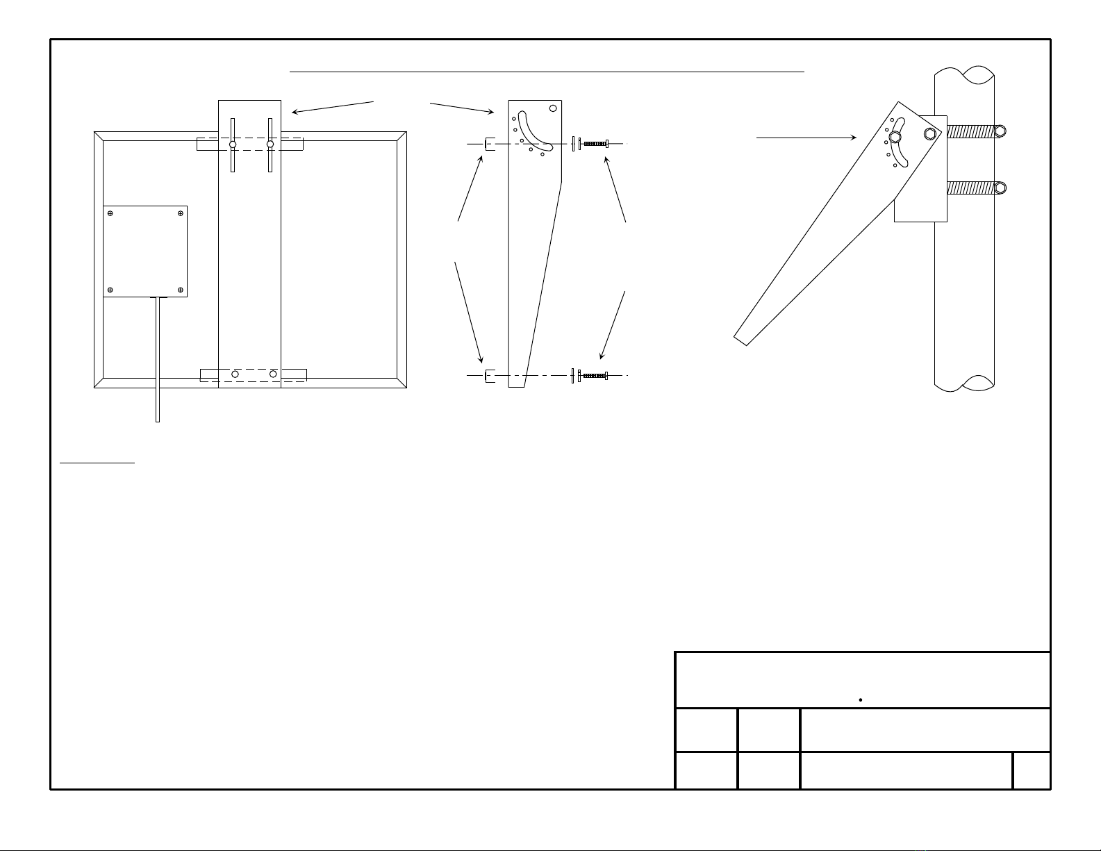
Solar Powered Top Beacon
with BDS mount assembly
www.LightedWindsocks.com
Support mounting pipe
part of windsock frame.
Pipe has a 3/4" NPT
connection on one end.
NOTES
1. The CTB Top Beacon/Obstruction Light is solar
powered with red LED's. The small solar panel for
this self-contained unit is on top of assembly.
Red LED’s standard. Other colors available.
2. The light assembly must be screwed on to top
pipe extending above the windsock frame.
3. This unit has been factory set to the following
flash code. (Steady Burn)
Flash code: 001, Steady Burn (Std)
Many other flash codes are available such as:
Flash code: 079, 2 seconds ON, 2 seconds OFF
Flash code: 078, 1 second ON, 1 second OFF
Flash codes can be field changed. See below.
4. Support mounting pipe must be mounted
securely to prevent damage to assembly.
Three (3) 10-32 X 1” SS machine screws
Three (3) 10-32” SS Nylon lock nuts.
Three (3) SS flat washers.
5. Do not drop or damage the assembly during
installation.
6. BDS always furnishes the CTB Top Beacon /
Obstruction Light with a clear lens with red LED’s.
If green or another color is required specify color of
light required.
BDS 740SPLWF-CTB (Solar Powered Top Beacon / Obstruction Light with support mounting assembly)
939 NATHANIEL TRAIL WARWICK, PA 18974
BDS SYSTEMS INC.

NO SCALE
DATE
DATE
DRAWN
APPD
REV
11/23/15
4/18/20
KLB
RBB
FRAMES & WINDSOCKS
www.LightedWindsock.com
939 NATHANIEL TRAIL WARWICK, PA 18974
BDS SYSTEMS INC.
939 NATHANIEL TRAIL WARWICK, PA 18974
BDS SYSTEMS INC.
WINDSOCK
FRAME ASSEMBLY (Non-Lighted)
16" X 1" OD
SS tubing
inside, a 5” nipple
with 1” NPT
connection
NOTES
PART NO.
MAT’L (Nylon)
INT'L ORANGE
INT'L ORANGE
INT'L ORANGE
INT'L ORANGE
INT'L ORANGE
W185-IO
W188-IO
W248-IO
W3610-IO
W3612-IO
WINDSOCKS
MODEL
WF18
WF24
WF36
FRAMES
WF18
WF36
(a) All standard International Orange (nylon), other materials available
(b) Windsocks are FAA approved
(c) Frames all Stainless Steel or non-corrosive parts. No parts to rust.
No ball bearings - Delrin bearings. No maintenance
(d) Order frames and / or windsocks by model / part number/s
(e) All pricing in US dollars. Shipping FOB Warwick, PA USA
(f) Self-locking weather-resistant nylon black ties are supplied when
windsock & frame are ordered together on the same order.
(g) Letters & designs printed on windsocks - consult BDS Systems
(h) 18” lighted windsock frames standard, 24” and 36” available
(i) Lighted windsocks visit: www.LightedWindsocks.com
(j) All Items made in the USA
(k) Inches X 2.540 = cm Feet X 0.3048 = mts
(l) Cm X 0.3937 = inches Meters X 3.281 = feet
Schedule 40 PVC
sunlight resistant tubing
with Delrin bearing
both ends
Triple thickness, 2 hems
W/#2 brass gromments
on 4” centers
1/4" DIA. SS wire rods
(approx. 11" between WS
ring and support pipe)
FRAME INSTALLATION
1. Bottom frame connection supplied with a 1” NPT SS pipe nipple for
easy installation. (details shown at right)
2. Install on 1” or larger support pipe using proper couplings supplied
“By Others”. Check all screw connections.
Recommend 6’ or longer support pipe.
3. Install windsock on frame using self-locking nylon ties.
4. No parts to lubricate or service. No part will rust or corrode,
5. Windsock should be installed in an open free air space - not near fans,
stacks or other locations which will result in unreliable wind readings.
DOUBLE THICKNESS
ON END HEM
(BDS WF18, BDS WF24, & BDS WF36)
MOUTH - BODY - TAIL
18" 5' 0" 8"
18" 8' 0" 8"
36" 10' 0" 12"
36" 12' 0" 12"
24" 8' 0" 12"
(IN) (OUT)
(LENGTH)
WINDSOCK ANGLE & APPROXIMATE WIND SPEED
15 + MPH
10 - 12 MPH
5 MPH
Miles/hr X 1.609 + Kmts/hr
(Non-lighted)
Supplied as part
BDS supplied as
part of frame with
SS bolts and nuts
1” coupling supplied
“By Others”
1” support pipe supplied
“By Others”
-

LIMITED WARRANTY
BDS SYSTEMS INC. warrants each of its products to be free from defective material and workmanship for a period of one (1)
year (except as noted below) from date of shipment. BDS SYSTEMS INC. will remedy any defect which becomes apparent
under normal installation and operation; provided the item is delivered, transportation prepaid by owner, to our factory for
inspection. In all cases BDS SYSTEMS INC. will examine and be the sole judge of that constitutes defective material and
workmanship. Defects of material and workmanship under this warranty will be corrected free of charge, FOB our factory.
This warranty does not extend to any equipment which has been subject to abnormal wear and tear, accident, neglect, abuse,
misuse, improper installation, damage by an act of God, or used in violation of any instructions supplied by BDS SYSTEMS
INC., or to equipment which has been modified or serviced other than by BDS SYSTEMS INC., or its authorized
representative. BDS SYSTEMS INC. assumes no risk or liability as a result of failure of equipment furnished by others. No
warranty is applicable on any Xenon flash tubes, light bulbs, LED’s, or any other illuminating items. Items made of nylon or
other cloth materials have a warranty of 90 days from date of shipment.
Prior to return of equipment for warranty or repair, a letter of authorization to return must be sent to the factory with an
explanation of fault and the model number of the equipment.
This warranty represents the entire warranty of BDS SYSTEMS INC. over the equipment it manufactures and takes precedence
over all other warranties expressed or implied, and no person or representative is authorized to assume for BDS SYSTEMS
INC. any other obligation or liability in connection with the sale of such equipment.
Repair or replacement as provided under this warranty is the exclusive remedy of the purchaser. BDS SYSTEMS INC. shall not
be liable for any incidental or consequential damage for breach of any express or implied warranty on this product. Except to the
extent prohibited by applicable law, any implied warranty of merchantability or fitness for a particular purpose on the product is
limited by the provisions and to the duration of this warranty.
BDS SYSTEMS INC.
939 Nathaniel Trail
Warwick, PA 18974 USA
www.LightedWindsocks.com
BDS Systems Inc. 939 Nathaniel Trail, Warwick, PA 18974 215-345-0436
www.LightedWindsocks.com
Thank you for choosing BDS Systems.
After you have installed your lighted windsock we would appreciate if you
would take some digital pictures of the installation and email them to us.
Please let us know the location details and purpose of the installation. We
would like to feature this on our website: www.LightedWindsocks.com
My email address is: Kurt@LightedWindsocks.com
We appreciate your business. Thank you.
Kurt Balderson
Kurt Balderson
BDS Systems Inc.
Email: Kurt@LightedWindsocks.com
Web: www.LightedWindsocks.com
This manual suits for next models
2
Table of contents
Popular Inverter manuals by other brands


MULTIQUIP
MULTIQUIP DCA10SPX3 Operation and parts manual

Northern Lights
Northern Lights L944D, M944W, NL944D2, M30CW, M944T, NL944T2, and... Operator's manual

Westerbeke
Westerbeke 8.0 KW BCGTC - 50 Hz Operator's manual

Top Gin
Top Gin TG250 manual

Ryobi
Ryobi RY906300LP Operator's manual

SOLIS
SOLIS Solis-EPM3-5G-Plus Quick installation instructions


