PAW SolarBloC midi Basic DN 20 Installation and operation manual

PAW GmbH & Co. KG
Böcklerstr. 11, 31789 Hameln, Germany
Phone: +49-5151-9856-0, Fax: +49-5151-9856-98
E-mail: info@paw.eu, Web: www.paw.eu
2020/09 9976x0210x-mub-en – V01 1
Installation and Commissioning Instructions
Solar return stations
SolarBloC®midi Basic - DN 20
SolarBloC®maxi Basic - DN 25
SolarBloC®midi
DN 20
SolarBloC®maxi
DN 25

1 General Information
2 9976x0210x-mub-en – V01 2020/09
Contents
1General Information.....................................................................................................3
1.1 About these instructions ...............................................................................................3
1.2 About this product ........................................................................................................3
1.3 Designated use ............................................................................................................4
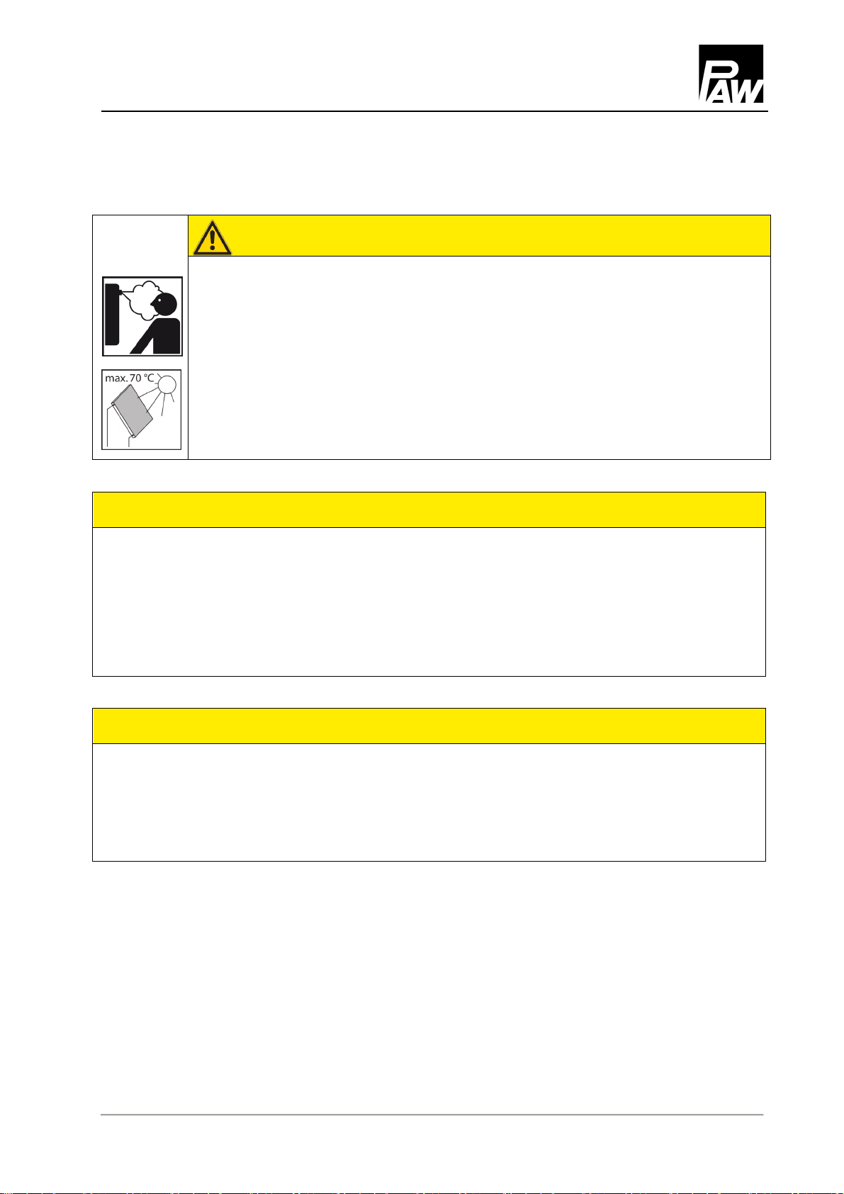
2Safety instructions .......................................................................................................5
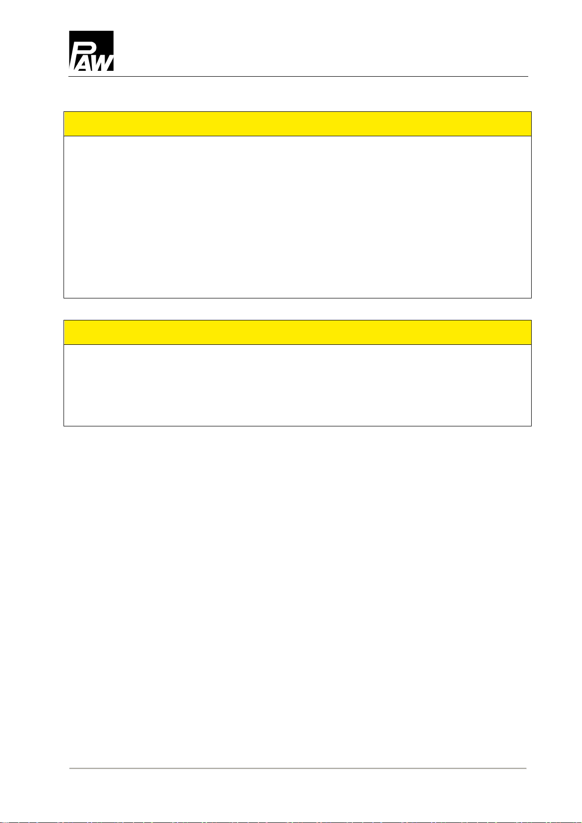
3Mounting and installation [specialist] .............................................................................7
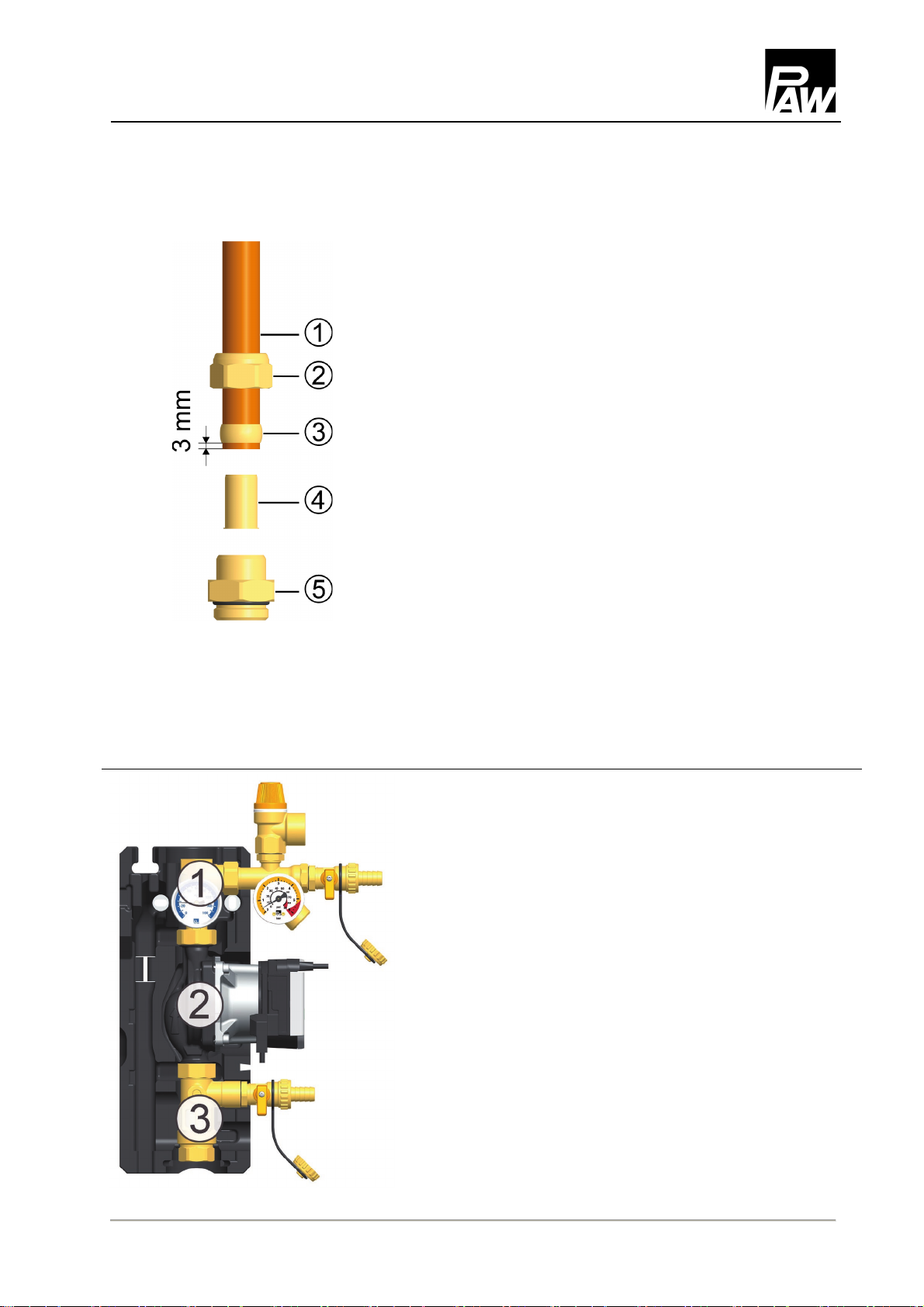
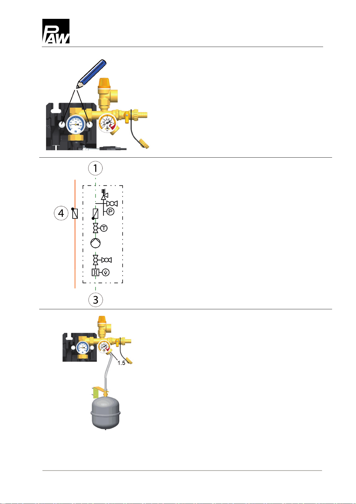
4Commissioning [specialist] ...........................................................................................9
4.1 Preparations before flushing....................................................................................... 11
4.2 Flushing and filling......................................................................................................11
4.3 Setting the solar installation........................................................................................ 13
5Maintenance [specialist]............................................................................................. 14
5.1 Draining the solar system...........................................................................................14
5.2 Deinstallation.............................................................................................................. 14
6Spare parts [specialist]............................................................................................... 15
6.1 SolarBloC®midi Basic DN 20 ..................................................................................... 15
6.2 SolarBloC®maxi Basic DN 25 .................................................................................... 17
7Technical data and pressure drop characteristic curve.................................................. 19
7.1 Pressure drop and pump characteristic curve SolarBloC®midi Basic DN 20 .............. 21
7.2 Pressure drop and pump characteristic curve SolarBloC®maxi Basic DN 25 ............. 21
8Commissioning report ................................................................................................ 22
9Disposal ................................................................................................................... 23
Item no. 9976x0210x-mub-en – Version V01 – Issued 2020/09
Translation of the original instructions
We reserve the right to make technical changes without notice!
Printed in Germany – Copyright by PAW GmbH & Co. KG
PAW GmbH & Co. KG
Böcklerstraße 11
D-31789 Hameln, Germany

1 General Information
2020/09 9976x0210x-mub-en – V01 3
1General Information
Carefully read these instructions before installation and commissioning.
Save these instructions in the vicinity of the installation for future reference.
1.1 About these instructions
These instructions describe the function, installation and commissioning of the solar return
stations SolarBloC®midi Basic DN 20 and SolarBloC®maxi Basic DN 25. The chapters
called [specialist] are intended for specialists only.
For other components of the solar installation, such as collectors, storage tanks, expansion
tanks and controllers, please observe the instructions of the corresponding manufacturer.
1.2 About this product
The station is a premounted group of fittings checked for tightness and used to circulate the
solar fluid in the solar circuit. It is mounted on a wall bracket and fixed with a clip. The station
contains important components and safety devices for the operation of the installation:
•Ball valve with exchangeable spindle
•Check valve
•Thermometer
•Pressure gauge to display the installation pressure
•Flowmeter to display the flow rate
•Ball valve to restrict the flow rate
•Solar pressure relief valve
•Connection for an expansion tank
•Flush and fill valves

1 General Information
4 9976x0210x-mub-en – V01 2020/09
1.3 Designated use
The solar station may only be used in solar thermal systems as a pump station in the solar
circuit, taking into consideration the technical limit values indicated in these instructions.
Due to its design, the station may only be installed and operated as described in this manual!
Only use PAW accessories with the solar station.
Improper usage excludes any liability claims.
Under the influence of solar radiation, the collectors will heat up
considerably.
The solar fluid in the solar circuit may heat up to more than 100 °C.
Only flush and fill the solar circuit when the collector temperatures
are below 70 °C.
required
onsite

2 Safety instructions
2020/09 9976x0210x-mub-en – V01 5
2Safety instructions
The installation and commissioning as well as the connection of electrical components require
technical knowledge commensurate with a recognised vocational qualification as a fitter for
plumbing, heating and air conditioning technology, or a profession requiring a comparable
level of knowledge [specialist].
The following must be observed during installation and commissioning:
•relevant local and national regulations
•accident prevention regulations of the professional association
•instructions and safety instructions mentioned in these instructions
WARNING
Danger of scalding due to the escape of hot fluids!
With pressure relief valves, there is a risk of scalding due to the escape of
vapour or hot fluid.
Please ensure for each pressure relief valve that no personal injury or
material damage may occur due to possibly escaping medium.
Install a discharge line.
Observe the instructions regarding the pressure relief valve.
The pressures calculated by the installation planner for the expansion
tank and the operating pressure of the installation must be set.
CAUTION
Personal injury and material damage due to overpressure!
Closing both ball valves in the primary circuit will separate the safety group from
the heat exchanger. A rise in temperature in the storage tank may result in high
pressures, which may lead to personal injury and material damage!
Only close the ball valves for service and maintenance.

2 Safety instructions
6 9976x0210x-mub-en – V01 2020/09
ATTENTION
Material damage due to mineral oils!
Mineral oil products cause lasting damage to seals made of EPDM, whereby the sealant
properties are lost. We do not assume liability nor provide warranty for damage to property
resulting from sealants damaged in this way.
It is imperative to prevent the EPDM sealing elements from making contact with
substances containing mineral oils.
Use a silicone- or polyalkylene-based lubricant free of mineral oil, such as
Unisilikon L250L and Syntheso Glep 1 from Klüber or a silicone spray.
ATTENTION
Material damage due to high temperatures!
Since the solar fluid near the collector can be very hot, the group of fittings must be installed at
a sufficient distance from the collector field. It may be necessary to install an intermediate tank
in order to protect the expansion tank.

3 Mounting and installation [specialist]
2020/09 9976x0210x-mub-en – V01 7
3Mounting and installation [specialist]
Not included in the scope of delivery!
Accessories: compression fitting
1. Push the union nut ② and the cutting ring ③ onto the
copper pipe ①. The pipe must protrude at least 3 mm
from the cutting ring in order to ensure the force
transmission and the sealing.
2. Insert the support sleeve ④ into the copper pipe.
3. Insert the copper pipe with the plugged-on individual
parts (②, ③ and ④) as far as possible into the body
of the compression fitting ⑤.
4. First, screw the union nut ② manually.
5. Tighten the union nut ② by rotating one full turn.
Secure the body of the compression fitting ⑤ against
distort in order to avoid damaging the sealing ring.
1. Remove the station from the packaging.
2. Remove the insulating front shell.

3 Mounting and installation [specialist]
8 9976x0210x-mub-en – V01 2020/09
3. Copy the dimension of the mounting holes of the
solar station on the mounting surface (see arrows).
4. Drill the holes and mount the solar station to the wall
with appropriate wall plugs and screws.
5. Connect the solar station to the installation
by using the pipes:
① Return to the collector field
③ Return from the storage tank
All thread connections have ¾" internal threads.
6. In order to prevent unwanted circulation, it is
mandatory to mount an additional check valve ④
in the flow on site.
Optionally available!
7. Connect the pipe for the expansion tank below
the pressure gauge [1.5] and fix the bracket for
the expansion tank.
8. Adapt the initial pressure of the expansion tank to the
installation and connect the expansion tank. Observe
the separate instructions for the expansion tank!
9. Check all screw connections and tighten them if
necessary.
The assembly of the solar station is now completed
and the station can be put into operation.

4 Commissioning [specialist]
2020/09 9976x0210x-mub-en – V01 9
4Commissioning [specialist]
Please observe the following safety instructions regarding the commissioning of the station:
WARNING
Risk of burning and scalding!
The valves and fittings may heat up to more than 100 °C. Therefore, do not clean
or fill the system when the collectors are hot (intense sunshine). Please note that
hot solar fluid will leak from the safety valve when the system pressure is too high!
During venting the solar fluid may escape as vapour and result in scalding!
Flush and fill the system only when the collector temperatures are below
70 °C.
ATTENTION
Risk of frost!
It often happens that solar systems cannot be completely drained after flushing. Thus, there
is a risk of frost damage later on when flushing with water. Therefore, only use the solar fluid
used later on for flushing and filling the solar installation.
Use a water/propylene glycol mixture with max. 50% of propylene glycol as solar fluid.
ATTENTION
Note regarding the commissioning sequence
During commissioning, fill the heating circuit first and the solar circuit afterwards.
This guarantees that the heat possibly absorbed by the collectors during
commissioning can be dissipated.

4 Commissioning [specialist]
10 9976x0210x-mub-en – V01 2020/09
The fill and drain valves necessary to flush and fill the installation are integrated in the solar
station.
To flush the dirt particles out of the installation, only use flush and fill stations with fine filters.
Ball valve with integrated check valve
(Flow direction in the figure: upwards)
0°
45°
90°
Check valve is operating,
flow only in flow direction.
Check valve is not operating,
flow in both directions.
Ball valve closed,
no flow.
14

4 Commissioning [specialist]
2020/09 9976x0210x-mub-en – V01 11
4.1
Preparations before flushing
The solar circuit is flushed in the direction
of flow.
1. Disconnect the expansion tank from
the solar system. Please observe the
instructions of the expansion tank
manufacturer on this topic!
2. Close the return ball valve [1.2] (
90°
,
see page 10).
3. The ball valve [3.1] at the flow meter must
be open.
4. Connect the fill station to the solar station:
- Pressure hose to the fill valve [1.4]
- Flush hose to the drain valve [3.2].
4.2
Flushing and filling
1. Open the fill and drain valves [1.4|3.2].
2. Put the flush and fill station into operation
and flush the installation until the solar fluid
exits without bubbles.
3. During flushing, vent the solar installation
several times via the vent valves possibly
present.

4 Commissioning [specialist]
12 9976x0210x-mub-en – V01 2020/09
4. Slowly open the return ball valve [1.2]
to vent the pump section.
5. Close the drain valve [3.2] while the filling
pump is running and increase the system
pressure to about 5 bars. The system
pressure is displayed on the pressure
gauge. Close the fill valve [1.4] and switch
off the pump of the flush and fill station.
Consider the pressure relief valve (6 bars)!
6. Check the pressure gauge to see whether
the system pressure reduces and eliminate
leaks where necessary.
7. Reduce the pressure at the drain valve
[3.2] to the operating pressure.
8. Connect the expansion tank to the solar
circuit and set the operating pressure of
the solar installation by means of the flush
and fill station (for the required operating
pressure, see instructions of the expansion
tank).
9. Close the fill and drain valves [1.4|3.2].
10. Turn the check valves (in the return
ball valve [1.2] and in the flow line) into
operating position (
0°
, see page 10).

4 Commissioning [specialist]
2020/09 9976x0210x-mub-en – V01 13
11. Connect the additionally required controller
to the mains and set the solar circuit pump
to ON in the manual mode (see the
controller instructions).
12. Remove the hoses of the flush and fill
station and screw the sealing caps on
the fill and drain valves.
The closure caps are only for protection
against contamination. They are not
designed for high system pressures.
Their tightness is ensured by the
closed ball valves.
4.3 Setting the solar installation
1. Set the desired revolution speed of the solar pump depending on the required flow rate.
If necessary, the flow rate can be reduced by the ball valve [3.1] (only necessary if the
pump is not speed-controlled).
Please observe the specifications of the collector manufacturer for the correct adjustment
of the flow rate.
2. Mount the insulating front shell of the solar station.
3. Set the automatic mode on the controller (see controller manual).
Scale DN 20:
3 – 22 l/min
Scale DN 25:
5 – 40 l/min
Reading edge =
round edge
of the float
Example: about 4 l/min

5 Maintenance [specialist]
14 9976x0210x-mub-en – V01 2020/09
5Maintenance [specialist]
5.1 Draining the solar system
1. Switch off the controller and secure it against
being switched on again.
2. Open the check valve in the return ball valve [1.2]
by turning the ball valve into position
45°
(see page 10).
Open the check valve possibly present in the flow
line.
3. Connect a heat-resistant hose to the lowest drain
valve of the solar installation (possibly drain valve
[3.2]). Make sure that the solar fluid is collected in
a heat-resistant container.
WARNING
Danger of scalding due to hot solar fluid!
The escaping solar fluid can be very hot!
Position and secure the heat-resistant collecting container such that
persons nearby are not put at risk when the solar system is drained.
4. Open the drain valve at the lowest point of the solar installation.
5. Open the vent valve possibly present at the highest point of the
solar installation.
6. Dispose of the solar fluid observing the local regulations.
5.2
Deinstallation
1. Drain the solar installation as described above.
2. Disconnect the pipe connections to the solar installation.
3. To remove the solar station from the mounting plate, pull out
the clip springs laterally with a screwdriver.
4. Remove the station by pulling it forward.

6 Spare parts [specialist]
2020/09 9976x0210x-mub-en – V01 15
6Spare parts [specialist]
NOTICE
Complaints and requests/orders of spare parts will only be processed with information on
the serial number!
The serial number is placed on the safety group of the solar station.
In case of a complaint, please send us the entirely completed commissioning report
on page 22.
6.1 SolarBloC®midi Basic DN 20

6 Spare parts [specialist]
16 9976x0210x-mub-en – V01 2020/09
Position
Spare part
Item number
1 Return ball valve DN 20,
¾" int. thread x F ¾" x ¾" ext. thread on the right, solar check valve N00290
2 Solar pressure relief valve ½" x ¾", MSV 6 bars N00300
3 Pressure gauge 0-6 bars / 0-90 psi,
with automatic isolation ⅜" ext. thread, d = 50 mm, 130°C N00301
4 Dial thermometer, blue scale, d = 50 mm, 0-160 °C N00194
5
Alternative pumps:
Wilo Para ST 15/7 N00150
Wilo Para ST 15/13 N00299
Grundfos UPM3 Solar 15-75 N00025
Grundfos UPM3 Solar 15-145 N00215
6 Flow meter ¾", 3-22 l/min, DN 20,
1" M x ¾" int. thread x ½" int. thread, with fill and drain valve N00225
7 Sealing kit consisting of 10 pieces, ½", for thread connection 1" N00024
8 Union nut G 1", passage 28.1 mm, wrench size 37, octagonal N00302
Not
shown in
drawing
Pump cable for Wilo Para ST, 2 m N00152
Pump cable for Grundfos UPM3 Solar N00199
PWM connection cable for Wilo Para ST, 2 m, U < 24 V N00342
PWM connection cable for Grundfos UPM3 Solar N00372
Connection of the high-efficiency pumps
Wilo Para ST 15/7
Wilo Para ST 15/13
Grundfos UPM3 Solar 15-75
Grundfos UPM3 Solar 15-145
PWM
Brown
GND
Blue

6 Spare parts [specialist]
2020/09 9976x0210x-mub-en – V01 17
6.2 SolarBloC®maxi Basic DN 25

6 Spare parts [specialist]
18 9976x0210x-mub-en – V01 2020/09
Position
Spare part
Item number
1 Solar ball valve DN 25 return, F 1" x 1" int. thread,
snap-in assembly, with check valve 200 mm wc N00306
2 Solar pressure relief valve ½" x ¾", MSV 6 bars N00300
3 Pressure gauge 0-6 bars / 0-90 psi, with automatic isolation
⅜" ext. thread, d = 50 mm, 130°C N00301
4 Dial thermometer, blue scale, d = 50 mm, 0-160 °C N00194
5
Alternative pumps:
Wilo Stratos PARA 25/1-11 T11 N00303
Wilo Para ST 25/8 N00263
Grundfos UPM3 Solar 25-75 N00035
Grundfos UPM3 Solar 25-145 N00304
Grundfos Solar PML 25-145 N00226
6 Flow meter 1", 5-40 l/min, DN 25, 1½" union nut x 1" int. thread
x ½" int. thread, with fill and drain valve N00227
7 Union nut G 1½", passage 42 mm, wrench size 52, octagonal N00269
8 Sealing kit consisting of 10 pieces, 1", for thread connection 1½" N00036
Not
shown in
drawing
Pump cable for Wilo Para ST and Grundfos Solar PML, 2 m N00152
Pump cable for Grundfos UPM3 Solar N00199
PWM connection cable for Wilo Para ST and Grundfos Solar PML N00342
PWM connection cable for Grundfos UPM3 Solar N00372
Connection of the high-efficiency pumps
Wilo Stratos PARA 25/1-11 T11
Wilo Para ST 25/8
Grundfos UPM3 Solar 25-75
Grundfos UPM3 Solar 25-145
Grundfos Solar PML 25-145
PWM
Brown
GND
Blue

7 Technical data and pressure drop characteristic curve
2020/09 9976x0210x-mub-en – V01 19
7Technical data and pressure drop characteristic curve
Dimensions
SolarBloC
®
midi DN 20
SolarBloC
®
maxi DN 25
Height (with pressure relief valve) 383 mm 474 mm
Width (with fill and drain valve) 256 mm 258 mm
Depth (with insulation) 150 mm 202 mm
Pipe connections ¾" internal thread 1" internal thread
Connection for expansion tank ¾" external thread, flat sealing
Outlet of pressure relief valve ¾" internal thread
Operating data
Max. admissible pressure 6 bars
Max. operating temperature 120 °C
Max. short-time temperature 160 °C, < 15 minutes
Max. propylene glycol content 50 %
Equipment
Pressure relief valve 6 bars
Pressure gauge 0-6 bars
Check valve 200 mm wc, can be opened
Flow meter 3-22 l/min 5-40 l/min
Materials
Valves and fittings Brass
Gaskets EPDM
Check valves Brass
Insulation EPP, λ= 0.041 W/(m K)

7 Technical data and pressure drop characteristic curve
20 9976x0210x-mub-en – V01 2020/09
SolarBloC®midi Basic DN 20
SolarBloC® maxi Basic DN 25
Other manuals for SolarBloC midi Basic DN 20
1
This manual suits for next models
1
Table of contents
Other PAW Inverter manuals
Popular Inverter manuals by other brands

Solar Stik
Solar Stik PSS-G Deployment guide

FujiFilm
FujiFilm FU-SUN-15K-G03 user manual

SCS Sentinel
SCS Sentinel SolarGate AAM0095 Installation and user manual

Lenze
Lenze L-force HighLine C 8400 Series Reference manual

PSC
PSC XANTRA VV ADVANCED Installation and operating instructions

Kohler
Kohler 99EOZDJ installation instructions