BE Ag & Industrial BE-BK Series Application guide

BE-BKxx
Backhoe
Operations & Parts Manual
• BE-BK61 • BE-BK71
For Models:
Purchase Date
Dealer
Model No. Serial No.

Understand that your safety and the safety of other persons is measured by how you service and operate this
backhoe. Know the position and operations of all controls before you try to operate. Make sure you check all
controls in all safe area before starting.
Read this manual completely and thoroughly and make sure you understand all controls. All equipment has a
limit. Make sure you are aware of the stability and load characteristics of this backhoe before you begin
operation.
The safety information given in this manual does not replace any safety codes, insurance needs, federal, state
and local laws. Make sure your machine has the correct equipment required by your local laws and regulations.
Before starting the engine of your tractor, make sure all operation controls are in park lock or neutral position.
Operate controls only when seated in the operator’s seat.
Equip your tractor with a ROPS cab or frame for your protection. See your tractor operator’s manual for
correct seat belt usage.
A frequent cause of personal injury or death in persons falling o and being run over. Do not permit others
to ride on your tractor. Only one person, the operator, should be on the machine when it is in operation.
Before leaving the tractor, stop the engine, put all controls in neutral, engage the parking brake and remove
the key from the ignition.
When using remote hydraulic tractor valves on some tractors, the backhoe’s cylinder will continue moving
unless the control levers are manually returned to neutral, or until relief pressure is reached at the ends of
piston strokes. Observe the bucket movement and maintain control with the control levers.
Stop the backhoe arms gradually when lowering or lifting loads. Stay o of slopes too steep for safe operation.
Shift down before you start up or down before you start up or down a hill with a heavy loads.
Avoid “free wheeling”.
Travel speed should be such that complete control and machine stability is maintained at all times. Where
possible, avoid operating operation near ditches, embankments and holes. Reduce speed when turning,
crossing slopes and on rough, slick or muddy surfaces.
Never use your hand to check for suspected leaks under pressure. Use a piece of cardboard or wood for this
purpose. Escaping hydraulic oil or diesel fuel leaking under pressure can have sucient force to penetrate the
skin and cause infection or other injured by leaking fluid, seek medical attention immediately.
To prevent personal injury, relieve all pressure before disconnecting fluid lines.
SAFETY PRECAUTIONS BE-BKxx
CAUTION This safety alert symbol indicates important safety messages in this manual.
When you see this symbol, carefully read the message that flows and be alert to the possibility
of personal injury or death.

SAFETY PRECAUTIONS (CONT.) BE-BKxx
Before applying hydraulic pressure, make sure all hydraulic connections are tight and components are in
good condition.
Contact with overhead power lines can cause severe electrical burn or death from the electrocution. Make sure
there is enough clearance between raised equipment and overhead power lines.
Add recommended rear tire liquid weight or rear wheel weights for increased stability.
A backhoe attachment should be transported in a low position at slow ground speeds. Make turns slowly and
the tractor brakes cautiously. A loaded attachment in the raised position alters the center of gravity location
of the machine and increase the possibility of mishaps.
Do not stand, walk or work under a raised backhoe or attachment unless it is securely blocked or held in
position. Accidental movement of a control lever or leak in the hydraulic system could cause the backhoe to
drop, or attachments to dump, causing severe injury.
Make sure all parked backhoes on stands are on a hard level surface with all safety devices engaged to prevent
backhoe from falling and being damaged or injuring someone.
When using a backhoe, be alert of bucket, boom and arm position at all times.
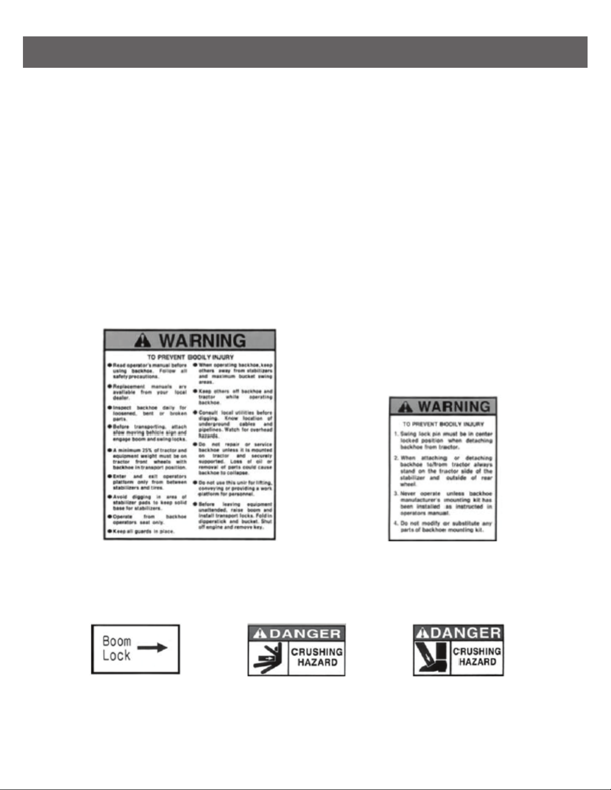
SAFETY DECALS BE-BKxx
SAFETY DECAL LOCATION
IMPORTANT: Warning decals are visible when getting on backhoe. Refer to the left and right hands used in
this manual, it’s the position of the operator when seated in the operating positions of the backhoe.
CARE OF SAFETY DECALS
1. Keep safety decals clean and free of obstructing material.
2. Clean safety decals with soap and water and dry with a soft cloth.
3. Replace damaged or missing safety decals with new decals from your local dealer.
4. If a component with a safety decal(s) axed is replaced with a new part, make sure new safety decals(s)
are attached in the same location(s) as the replaced components.
5. Mount new safety decals by applying on a clean dry surface and pressing air bubbles to outside edges.
Location: MainframeLocation: Both Sides of Mainframe
Location: Both
Sides of Mainframe
Location: Both
Leg Cylinders
Location: Beside
Locking Hole at
Boom Mainframe

SAFETY DECALS (CONT.) BE-BKxx
Location: Main Valve Cover
Location: Left Side Valve Lever Location: Right Side Valve Lever
Location: Right
Leg Guard
Location: Main Valve Cover
Location:
Side of Left
Inner Lever
Location:
Side of Right
Inner Lever
Location: Both Sides
of Dipper Stick
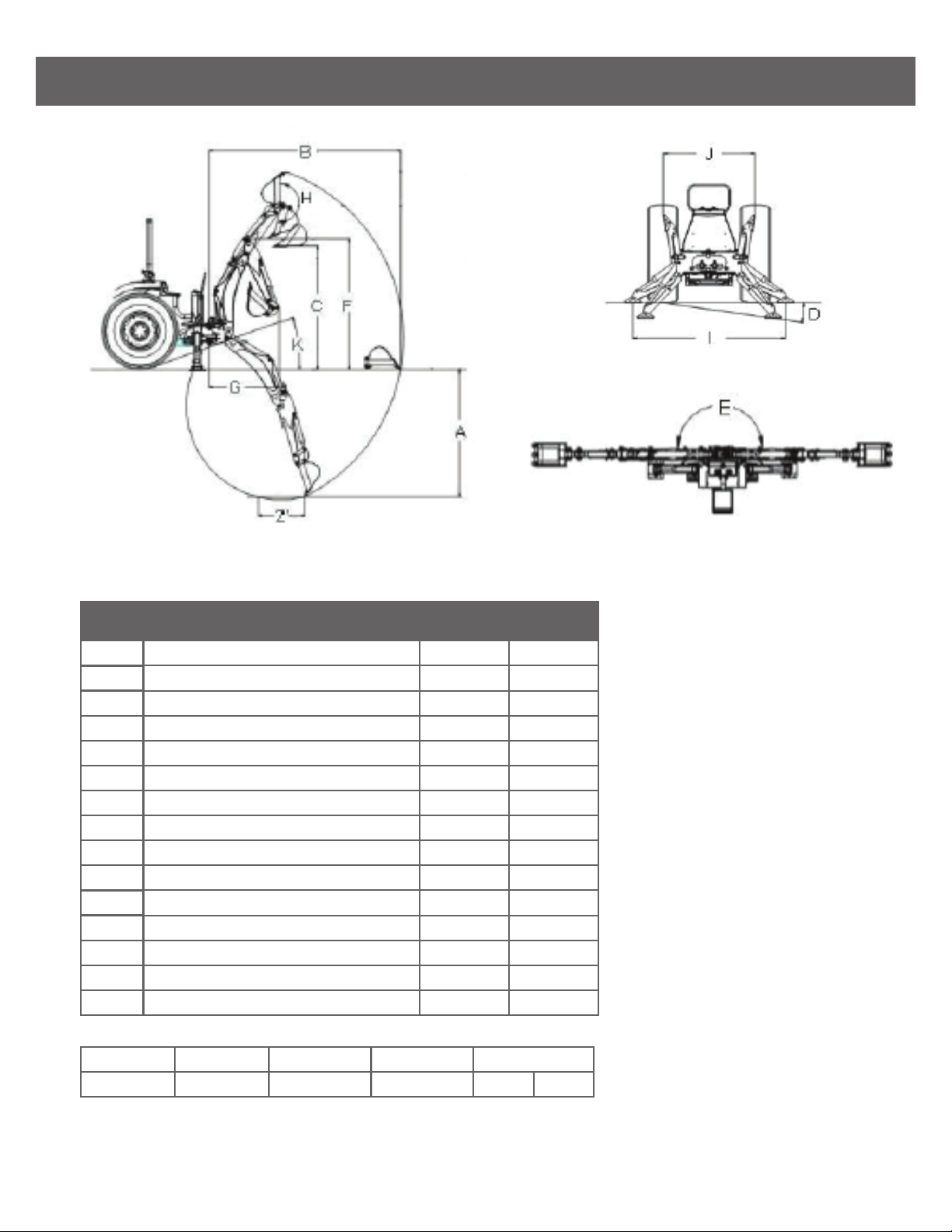
BACKHOE SPECIFICATIONS BE-BKxx
REF NO. DESCRIPTION BE-BK61
Digging Depth (2ft Flat Boom)A 1860mm
Reach From Center Line of Swing PivotB 2820mm
Loading Height (Bucket At 60°)C 1590mm
Maximum Leveling AngleD 10°
Swing ArcE 180°
Transport Height (Maximum)F 1880mm
Transport OverhangG 1145mm
Bucket RotationH 180°
Stabilizer Spread (Down Position)I 1730mm
Stabilizer Spread (Up Position)J 1320mm
Angle of DepartureK 21°
Shipping Weight (Without Bucket) 430kg
Bucket Digging Force 1050kg
Dipperstick Digging Force 700kg
Operating Pressure 160bar
10°
21°
BE-BK71
2160mm
3277mm
2032mm
180°
1930mm
1320mm
180°
1730mm
1320mm
463kg
1180kg
860kg
160bar
Bucket
12”
Teeth Qty
3
Struck Capacity
1.01 cu. ft.
Heaped Capacity
1.24 cu. ft.
Shipping Weight
35kg 77 lbs
Specifications may vary depending on tractor model, tire size and bucket used.

INTRODUCTION BE-BKxx
The purpose of this manual is to assist you in maintaining and operating your backhoe. Read it carefully,
it furnishes information and instructions that will help you achieve years of dependable performance. Some
information may be general in nature due to unknown and varying conditions. However, through experience and
these instructions, you should be able to develop operating procedure suitable to your particular situation.
“Right” and ”Left” as used throughout this manual are determined by facing the direction the machine will travel
when in use.
The photos, illustrations and data used in this manual are current at the time of printing, but due to possible
in-line production changes, your machine may vary slightly in detail. The manufacturer reserves the right to
redesign the machine as may be necessary without notification.
IMPORTANT
Illustrations used in this manual may not show all safety equipment that is recommended to ensure safe
operation of tractor and backhoe. Refer to the Safety Precautions section of this manual for information
concerning safety. Consult your dealer for further information.
SERIAL NUMBER & LOCATION
The serial number is important information about the machine it may be necessary to know it before obtaining
the correct replacement part. The serial number is located on the right side of backhoe mainframe. The serial
number should be recorded on the Delivery and Registration from and also below for your reference.

TRACTOR PREPARATION BE-BKxx
Rear Counterweight
ROPS SYSTEM
The tractor must be equipped with an approved ROPS System to ensure adequate operator’s protection.
TRACTOR HYDRAULIC SYSTEM
The tractor operation in a backhoe application significantly increase demands on the tractor Hydraulic System.
Check the tractor Hydraulic system fluid level daily. Refer to your tractor Operator’s Manual maintenance
section for instructions regarding tractor hydraulic system maintenance.
Adhere to recommendation in your Tractor Operator’s Manual concerning hydraulic fluid and filter
specifications and change intervals.
TIRE INFLATION
Front tires must be maintained at the maximum recommended inflation to maintain normal tire profile with
the added weight of backhoe/material.
Rear tires must be maintained at equal pressure within the recommended tire inflation range. Unequal rear
tire inflation can prevent backhoe attachment from contacting the ground across its full width.
WHEEL TREAD SETTINGS
Tractor front wheel tread setting must be restricted to wheel tread spacing recommended in the tractor
Operator’s Manual.
WARNING Do not exceed the manufacturer’s rating for maximum gross vehicle weight.
Refer to Operator’s Manual or ROPS serial plate provided with tractor.
Certain specific conditions may not permit safe use of backhoe at backhoe rating or may require
more careful restricted operation at the rated load.
WARNING The tractor/backhoe must only be operated
with all safety equipment properly installed.

BACKHOE OPERATION BE-BKxx
CAUTION The tractor/backhoe should only be operated with all safety equipment properly
installed. Keep assistants or by standers a safe distance from the equipment operating area.
PRECAUTIONARY NOTES
• Check below items before operating for your safety.
• Read and understand this manual to avoid accidents.
• Check the hydraulic fitting lines to be correct and set tightly.
• Maintain and repair (if it is needed) the parts or assemblies, check bolts and pins to be sure they are
positioned tightly.
• Check tractor with tractor operator’s manual that it can be prepared for operating.
• Warm up and operate the tractor and backhoe carefully. Purge any air in the hydraulic lines and cylinders
by fully cycling all cylinders several times.
• Check hydraulic level in the tank. It should be full (Refer to the Tractor Operator’s Manual).
• Do not operate the hydraulics when not seated in the backhoe operators seat.
• Keep all assistants out of area of operation.
• Do not operate rapidly.
• Do not allow riders other than the operator to be on the tractor while operating.
IMPORTANT
Use tractor engine speed that your experience permits. At first set PTO RPM of the tractor to slow.
Do not use the boom, dipperstick, swing and stabilizers to lift, push or full objects. Use only to maneuver and
operate the bucket.
Practice quickly turning o the engine or stopping the backhoe immediately in case of an emergency.
Do not operate while the rear tractor wheels are o the ground by stabilizer. It is dangerous to operate the
backhoe while rear wheels are o the ground. Position vehicle so that the backhoe is as near to the pile as
possible and in such a direction as to minimize the amount of tractor turning required to dump. Keep the unit
clean and perform regular service. Observe safety messages whenever cleaning, servicing or lubricating.
WE URGE YOU TO FOLLOW THIS ADVICE:
1. Read and understand this manual as well the Tractor Operator’s Manual.
2. Remember and observe the Safety Precautions brought to your attention in this manual, the tractor manual
and on the machinery itself.
3. Use good common sense in the everyday operation of this unit. Safety recommendations can never be
all-inclusive and you are responsible for watching out for and avoiding unsafe conditions.
4. Never exceed the limits of the machinery. If its ability to do a job, or to do so safely, is in question, don’t try it.
5. Don’t hurry the learning process or take the unit for granted. Ease into it and become familiar with your
new backhoe and tractor.

BACKHOE OPERATION BE-BKxx
CAUTION
When lowering a heavy load, ease it downward slowly. Never drop a loaded attachment and
“catch it hydraulically”. Stopping a load after it has gained downward momentum places undue
strain on the unit and may cause unnecessary damage to the backhoe or tractor or even worse,
personal injury.
Before disconnecting hydraulic lines, relieve all hydraulic pressure. Escaping hydraulic oil under
pressure can have sucient force to penetrate the skin causing serious personal injury. If inured
by escaping hydraulic oil, seek medical attention immediately.
Do not operate the backhoe if the fittings are leaking or if the hoses are damaged. A sudden line
burst would cause the boom, or dipperstick bucket to drop suddenly, causing damage to the
tractor or backhoe or injury to personnel.
INITIAL BACKHOE OPERATION
Before operating the backhoe, fully raise and lower the boom, arm, swing and stabilize two or three times.
Then raise the bucket above the ground and cycle the bucket cylinders three times. Lower the bucket to
the ground.
Check the tractor hydraulic oil and the correct oil level.
Always keep cylinders in a retracted position when the backhoe is not in use to guard against rust and
contamination which may cause damage to the cylinder rods or hydraulic system. Also, lock the swing and
boom while tractor is moving and storing for an extended period of time.
COLD WEATHER OPERATION
For smooth operation in cold weather, let the tractor warm up. Slowly cycle all of the cylinders several times
to warm the oil in the hydraulic system. The backhoe may operate erratically until the hydraulic oil has
warmed up to operating temperatures.
CAUTION Before leaving the machine, stop the engine, remove the key, place all
controls in neutral, and either set the parking brake or place tractor in park as equipped.
CAUTION Operate controls only when seated in the operator’s seat.
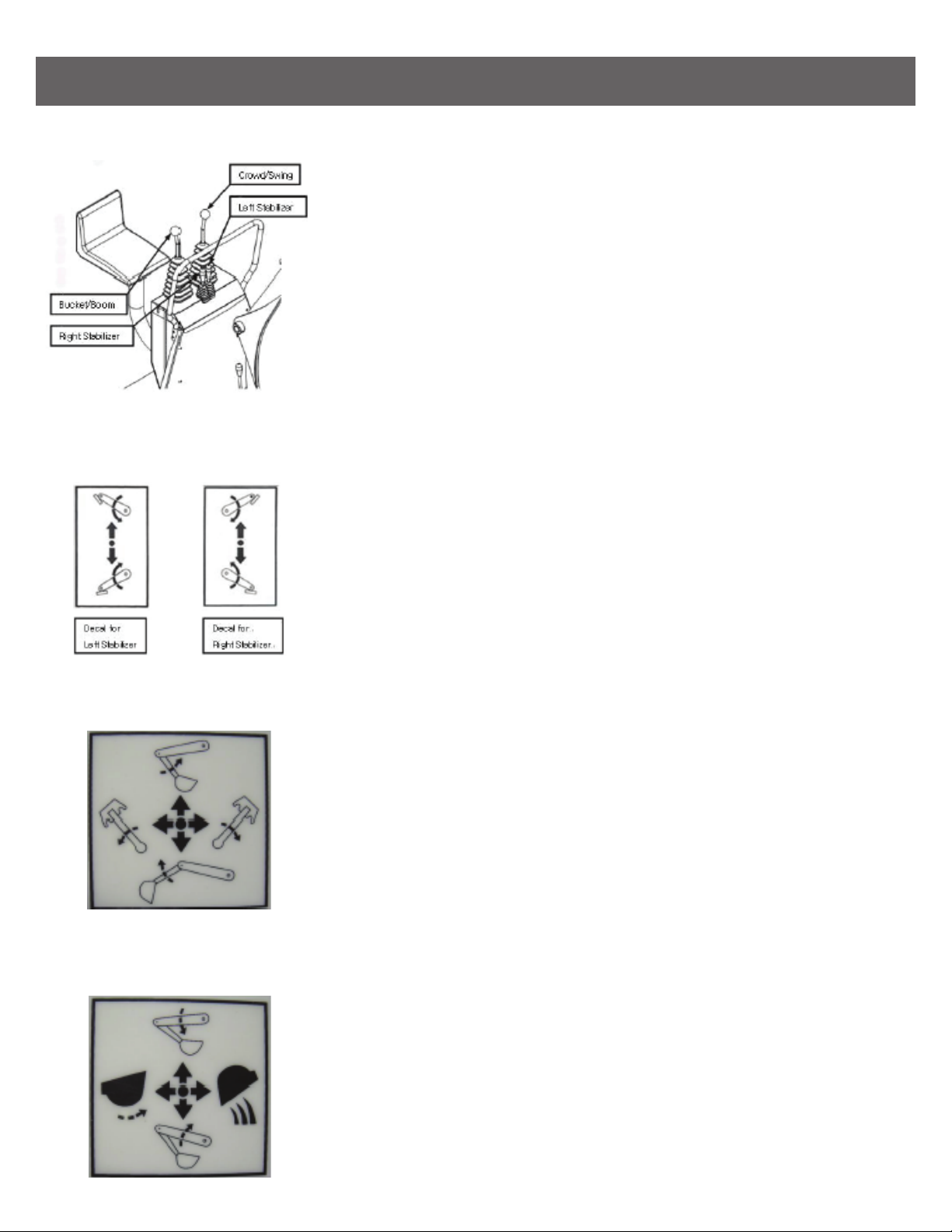
BACKHOE OPERATION (CONT.) BE-BKxx
Push the left-hand inner control lever, left stabilizer lowers. Pull up
the lever, left stabilizer raises. Push the right-hand inner control lever,
Right stabilizer lowers. Pull up the lever, right stabilizer raises. Do not
dig near the stabilizers to avoid possible accident. Do not lift the
tractor rear wheels by stabilizers. Also, be sure the stabilizers are
seated on hard ground to support the backhoe/tractor.
Push the left-hand outer control lever, arm (dipperstick) moves toward
the operator. and pull back the lever, arm moves away from the operator.
Move the left-hand outer control lever to the left, boom swing moves to
the left. Move lever right, boom swing moves to the right.
Push the right-hand outer control lever, boom moves down, and pull back
the lever, boom moves up.
Move the right hand outer control lever to the left, bucket curls in. Move
lever right, bucket extends out from operator.
Left and Right Stabilizer Controls
Left and Right Stabilizer Controls
Crowd and Swing Controls
Bucket and Boom Controls

BACKHOE OPERATION (CONT.) BE-BKxx
These two levers (crowd & swing control lever, bucket & boom control lever) provide four simultaneous
operations. Both experience and practice are needed to eliminate excess motion and increase operating
eciency.
Observe the following safety warnings when working with your new backhoe/tractor:
Swing Lock & Boom Lock
When transporting or dismounting backhoe, you must
lock the backhoe’s swing and boom. Position boom
straight back and drop pin through holes in swing frame
and boom. When not in use, store pin i hole provided on
swing frame and boom.
CAUTION
When using a backhoe, be aware of bucket & boom location at all times. When raising arm
(dipperstick) with bucket rolled forward, material can spill onto non-target area causing injury
to assistant or damage other objects.
Do not dig near stabilizers. Ground under stabilizer could collapse. Make all movements slow
and gradual when practicing operation.
Operate from backhoe operators seat only. Pay attention, be ready to stop, immediately in case
of an emergency.
To help prevent roll-over, adjust the rear wheels to their widest setting to maximize stability.
Refer to your Tractor’s Operator’s Manual for recommendations.

BACKHOE REMOVAL BE-BKxx
CAUTION Move the backhoe to flat, firm and wide place to remove the equipment.
Do not allow to be removed without bucket and stabilizers. Also, dump the remaining material
from the bucket to empty. Use other lifting equipment to remove when the backhoe has damage.
CAUTION Remove the backhoe on firm level ground. Do not allow other persons in the area.
Be careful to avoid injury during removal of the backhoe.
The hydraulic oil is dangerous for skin or eyes. Wash the skin and seek medical service if it
is necessary.
1. Move the tractor to backhoe storage place.
2. Use inner two levers to lower the stabilizers until they contact ground. Use the boom and dipperstick control
lever to raise the boom and dipperstick completely.
3. Center the boom and then lock the swing with lock pin.
4. Using the control levers, position the dipperstick vertically, curl the bucket until it’s bottom is level with the
ground then lower the boom until bottom of the bucket rests on the ground.
5. Remove pins that secure the backhoe.
6. Lower the backhoe mainframe to the ground by raising stabilizers and boom. Use the wood plate or block
if necessary.
7. Turn o the tractor engine, relieve hydraulic pressure by actuating all the control levers in each direction,
then disconnect the backhoe hose couplers from the tractor hydraulic couplers.

LUBRICATION & MAINTENANCE BE-BKxx
SERVICE
INTERVAL
SERVICEITEM
Hydraulic System Oil Level
Hydraulic System Oil/Filter
Tire Inflation
Backhoe Pivot Points
Backhoe Hydraulic Lines,
Hoses, Connections
Boom, Arm, Swing & Bucket
Cylinder Rod Packing
Pivot Pin Bolts & Dust Covers
Friction of All Pins
Backhoe Mount Hardware
Bolts & Nut Release
Check
Replace
Check
Lubricate
Check for leaks, wear
Check for seepage,
service as needed
Check, replace if missing
Check, replace if necessary
Check visually
Re-torque
Daily/10 Hours
As specified in Tractor Manual
Weekly/50 Hours
Daily/10 Hours
Daily/10 Hours
Daily/10 Hours
Daily/10 Hours
Daily/10 Hours
Daily/10 Hours
Every 25 Hours
CAUTION Do not perform service or maintenance operations with backhoe raised o the ground.
For additional access to tractor components remove backhoe.
IMPORTANT Lower the backhoe to the ground and relieve pressure in backhoe hydraulic lines
prior to performing any service or maintenance operations on the tractor or backhoe.

LUBRICATION & MAINTENANCE (CONT.) BE-BKxx
CAUTION Escaping fluid under pressure can have sucient force to penetrate the skin,
causing serious injury. Before disconnecting lines, be sure to relieve all pressure. Before applying
pressure to the system, be sure all connections are tight and that lines, pipes and hoses are not
damaged. Fluid escaping from a very small hole can be almost invisible. Use a piece of cardboard
or wood rather than your hands to search for suspected leaks. If injured by escaping fluid, seek
medical attention immediately. Serious infection or reaction can develop if correct medical
treatment is not administered immediately.
CAUTION Do not operate the backhoe if the fittings are leaking or if the hoses are damaged.
A sudden line burst could cause the boom, dipperstick or bucket to drop suddenly, causing
damage to the tractor or backhoe or injury to personnel.
Operate the backhoe from the operator seat only.
Do not stand or walk under a raised backhoe. Accidental movement of control lever or leak in
hydraulic system could cause boom or dipperstick to drop, causing severe injury
Refer to “Lubrication & Maintenance Chart” for quick reference to Maintenance Operations.
Check the hydraulic system as outlined in the Tractor Operator’s Manual.
NOTE: When checking hydraulic system oil level, the backhoe should be on the ground and bucket fully
retracted (all cylinders in retracted position).
Grease all backhoe pivot points daily (10 hours). Refer to Tractor’s Operator Manual for lubricant
recommendations.
Inspect hydraulic hoses, connections, control valve and cylinders for evidence of leakage.
Tractor tires should be maintained at maximum recommended inflation to maintain normal tire profile with
added weight of backhoe/material. Unequal rear tire inflation can result in bucket not being level to the ground.

TROUBLE SHOOTING GUIDE
PROBLEM POSSIBLE CAUSE POSSIBLE REMEDY
Swing, Boom, Dipperstick & Bucket
Cylinders not operating properly.
• Check & replenish hydraulic fluid.
• Check & correct hydraulic hose
connections.
• Check for damage (kinked) hoses, etc.
• Check system pressure. Repair or
replace relief valve. Refer to the
Tractor Operator’s Manual.
• Check system pressure. Repair or
replace pump.
• Inspect. Replace as required.
• Check coupler connections. Replace
coupler(s) if necessary.
• Check for evidence of damage to
hoses or tube lines that would block
flow of oil between cylinders & control
valve.
• Check cylinders for internal leakage as
described under cylinder leakage tests.
• Inspect for blockage. Disassemble
valve if necessary.
• Low hydraulic fluid level.
• Hydraulic hoses connected improperly.
• Hydraulic hoses to/from control valve
are blocked.
• Backhoe control valve or tractor main
relief valve stuck open.
• Low system pressure supplied from
hydraulic pump.
• Control valve linkage broken.
• Quick disconnect coupler(s) are not
fully connected or “Flow Check”
• Hydraulic hose or tube line blockage.
• Cylinder piston assembly defective
(not sealing)
• Control valve blockage
Cylinders operate in wrong direction
relative to control valve lever position.
• Correct hydraulic hose connections.• Hydraulic hoses connected incorrectly.
Inadequate lifting capacity. • Increase engine RPM.
• Reduce Load.
• Check & reset relief valve setting as
needed.
• Check cylinders for leakage. Repair as
needed.
• Replace control valve & recheck
operation.
• Refer to “Hydraulic Pump Capacity
Inadequate”.
• Engine RPM too slow
• Excessive load. Material loading
exceeds specified backhoe capacity.
• Relief valve setting below
specifications.
• Bucket, Boom & Dipperstick Cylinder
Piston Assembly leakage.
• Control valve leaking internally.
• Hydraulic Pump defective.
The trouble shooting chart is provided for reference to possible backhoe operational problems. Determine the
problem that best describes the operational problem being experienced and eliminate the possible causes as
listed by following the correction procedures.

TROUBLE SHOOTING GUIDE
PROBLEM POSSIBLE CAUSE POSSIBLE REMEDY
Slow or erratic movement of Cylinder
(Noisy operation of cylinder).
• Check & replenish hydraulic fluid.
• Allow hydraulic system to warm up
to operating temperature.
• Check oil number & viscosity, Refill
correct hydraulic oil.
• Increase engine speed to obtain
satisfactory backhoe operation.
• Reduce material load (Digging load).
• Check control valve linkage & repair if
worn/defective.
• Refer to “aeration of Hydraulic Fluid”.
• Check coupler connections. Repair or
replace.
• Check hoses & tube lines for evidence
of restriction.
• Check cylinders for leakage. Repair as
needed.
• Check & reset relief valve. Setting as
needed.
• Replace control valve & recheck
operation.
• Low hydraulic fluid level.
• Cold hydraulic fluid.
• Hydraulic oil viscosity too heavy or
incorrect oil.
• Engine RPM too slow (hydraulic pump
RPM too slow).
• Excessive weight in bucket. Material
weight exceeds maximum specified
backhoe capacity.
• Control valve linkage binding/defective.
• Aeration of hydraulic fluid.
• Quick disconnect coupler restriction or
coupler “Flow checks”.
• Hydraulic hose or tube line restriction
(hoses/tube line) kinked or pinched.
• Boom, Dipperstick or Bucket cylinder
piston assembly leakage.
• Relief valve erratic or set below
specifications.
• Control valve leaking internally.
(hypassing fluid within valve).
Aeration of Hydraulic Fluid (Generally
indicated by foamy appearance of fluid).
• Check & refill hydraulic system to
proper level.
• Check for loose or defective
connections between hydraulic oil
using recommended hydraulic oil.
• Refer to Tractor Operator’s Manual
& replace hydraulic oil using
recommended hydraulic oil.
• Low hydraulic fluid level.
• Air leaking into suction side of
hydraulic pump.
• Hydraulic fluid foaming due to
improper hydraulic oil usage.
System relief valve squeals. • Allow hydraulic fluid to warm up to
operating temperature.
• Check oil number & viscosity, Refill
correct hydraulic oil.
• Reduce load.
• Check & reset valve setting as needed.
• Check for evidence of restriction in
hydraulic oil flow. Repair or replace
defective components.
• Cold Hydraulic Fluid.
• Hydraulic Oil viscosity too heavy or
incorrect oil.
• Excessive load in bucket. Loading
exceeds specified backhoe capacity.
• Relief valve setting below specifications.
• Hydraulic hose, tube line or quick
disconnect coupler restriction.

TROUBLE SHOOTING GUIDE
PROBLEM POSSIBLE CAUSE POSSIBLE REMEDY
Backhoe drops with valve spool in
“centered” position (no external oil
leakage evident) Note: A gradual drop
over an extended period of time is a
normal condition.
• Check cylinders for leakage.
• Replace control valve & recheck.
• Cylinder piston assembly leakage.
• Control valve internal leakage.
Control valve spool(s) will not return to
centered position.
• Determine origin of binding & repair.
• Replace centering spring.
• Disassemble valve for inspection &
repair.
• Control lever linkage binding.
• Control valve spool centering is broken.
• Control valve spool binding in valve
body spool bore.
External hydraulic fluid leakage. • Check for origin of oil leak & replace
defective part.
• Replace defective o-rings.
• Check cylinders for leakage. Repair as
needed.
• Loose hydraulic connection.
• Defective hydraulic hose, tube line,
adapter fitting or adapter fitting o-ring.
• Control valve spool or body damaged
or worn.
• Cylinder rod packing set leakage.
Hydraulic pump capacity inadequate.
Cylinder rod bend when cylinders
extended.
• Allow hydraulic fluid to warm up to
operating temperature.
• Increase engine RPM.
• Refer to Tractor Operator’s Manual for
service recommendations.
• Check for evidence of restriction in
hydraulic hoses.
• Refer to Tractor Operator’s Manual for
service recommendations.
• Check for evidence of restriction in
hydraulic hoses.
• Refer to Tractor Operator’s Manual for
recommended service procedures.
Replace hydraulic pump if determined
to be defective.
• Cold hydraulic fluid.
• Engine RPM too slow.
• Low hydraulic fluid supply.
• Hydraulic hose restriction.
• Hydraulic pump defective.
• Replace defective parts. Review and
observe proper and safe operational
practices.
• Excessive shock load on cylinder
during transport.

HYDRAULIC SYSTEM SCHEMATIC BE-BKxx
HYDRAULIC SYSTEM SCHEMATIC AUXILIARY HYDRAULIC VALVE PACKAGE.

TORQUE TIGHTENING CHART BE-BKxx
TORQUE TIGHTENING CHART 1
TORQUE TIGHTENING CHART 2
This manual suits for next models
2
Table of contents
Other BE Ag & Industrial Construction Equipment manuals


Popular Construction Equipment manuals by other brands


PennyHydraulics
PennyHydraulics SwingLift KJ operating & maintenance manual

Fayat Group
Fayat Group BOMAG BMF 2500 M Service manual

CRH
CRH Leviat HALFEN SP Assembly instructions

stellar labs
stellar labs 9630 owner's manual

Vestil
Vestil HOP-LP instruction manual

Manitowoc
Manitowoc 14000 Service maintenance manual


