Di-Acro 36 User manual

REV. D 9/12
1
DI-ACRO
#36 FINGER BRAKE
INSTRUCTION MANUAL

REV. D 9/12
2
TABLE OF CONTENTS
A. SAFETY INFORMATION PG. 3
B. ANGLE ADJUSTMENT PG. 4
C. #36 FINGER BRAKE BREAKDOWN AND PARTS LIST PG. 5-7
D. MICROMETER BACK GAUGE PG. 8
E. OPTIONAL STAND PG. 9
WARRANTY PG. 10

REV. D 9/12
3
A. SAFETY INFORMATION
Before brake is set up for operation, mount on work bench or stand*
with brake base flush with the front edge of stand or work bench and
bolt in place.
*IF BRAKE IS MOUNTED ON ITS OWN STAND, SECURE STAND TO FLOOR
REV. D 9/12
4
B. ANGLE ADJUSTMENT
To adjust Brake for bending clearance, raise folding blade 90 degrees,
insert material between edges of folding blade and leading edge of fingers
(for heavy material, clearance should be twice the thickness, less for
lighter gauge or if sharper bend is desired). Adjust finger mount
weldment by turning arm adjustment bolts (item 48). To adjust clamping
pressure, insert material under fingers and turn arm adjustment bolts
until material is held securely when fingers are lowered. To adjust
degree of bend, pins (item 44) located on both ends of folding blade for
desired degree of bend.
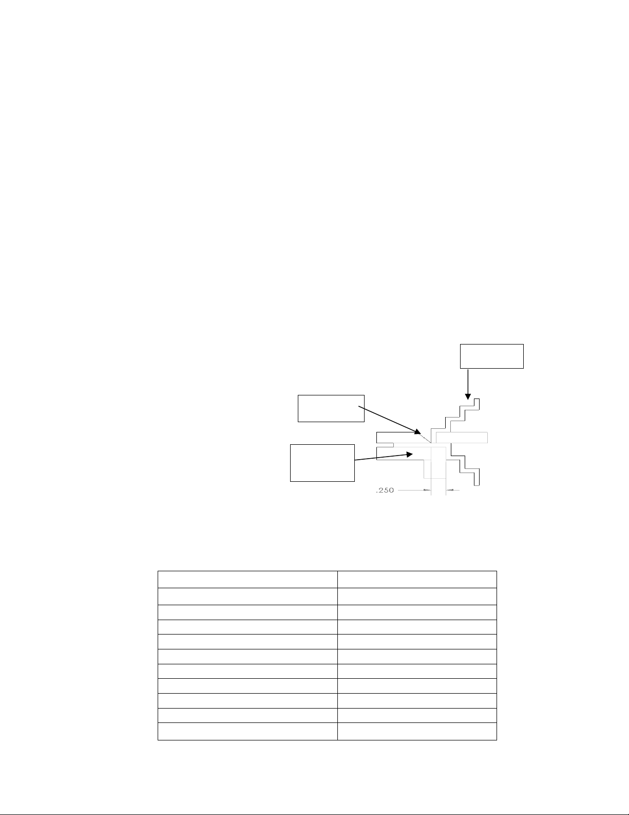
Reverse Bends
Remove the five Hex head cap screws 3/8-16x1 (item 67) the support bar
(item 64and adjust Brake as shown.
NOTE: 16 GAUGE CAPACITY (with support bar in place)
MINIMUM LENGTH OF BEND WHEN
FORMING A REVERSE BEND = 1/4
NOTE: Di-Acro Brakes are rated for 1” minimum flange when bending
full capacity. Caution should be used if necessary to bend heavier gauge
material in short widths.
SPECIFICATIONS
No. 36
in. mm
Max. Capacity, Mild Steel
16 ga. 1.5
Max. Forming Width
34 914.4
Clearance thru Top Opening
1 25.4
Max. Depth of Box or Pan
3 76.2
Min. Reverse Bend
¼ 6.4
Max. Angle Bend (one operation)
135°
Max. Back Gauge Adjustment
24 609.6
Shipping Weight
470# 123 kg
Stand, Shipping Weight
140# 63 kg
FINGERS
PART
BOTTOM
PLATE

REV. D 9/12
5
#36 FINGER BRAKE BREAKDOWN
8348820-080

REV. D 9/12
6
Parts List
8348820-080
ITEM
PART NUMBER
DESCRIPTION
QTY
1
30X0102C
NUT-FULL 1/2-13
2
2
8490500-100
WASHER SET
2
3
23A0104C0308
SCREW-SSS 1/4-20X3/8
2
4
8348111-000
FINGER MOUNT
1
5
8348310-700
THRUST BRG
4
7
8348510-200
SPRING
2
8
21A0104C0102
SCREW-HHCS 1/4-20X1/2
4
9
8348140-700
SPRING BRACKET
2
10
8348121-100
STUD
2
11
8348121-200
CONNECTING ARM
2
12
8120810-700
PLASTIC KNOB
1
14
8310300-900
NEEDLE BEARING
2
15
346-1208030
CLAMP HANDLE BLOCK
1
15A
8500111-300
CLAMP HANDLE ROD
1
16
21A0516C1104
SCREW-HHCS 5/16-18X1-1/4
1
17
21A0516C1308
SCREW-HHCS 5/16-18X1-3/8
16
19
8347110-203
FINGER CLAMP
16
20
8000122-203
FINGER STD 3/4
2
20
8100122-203
FINGER STD 1
2
20
8000122-204
FINGER STD 1-1/4
2
20
8200122-203
FINGER STD 3
2
20
8347122-204
FINGER STD 6
4
21
8700122-000
BRAKE SHAFT
1
22
8346110-302
BEARING ASSEMBLY (SEE
BELOW)
346-1103024
BUSHING HOUSING
2
8346110-302-1
BRONZE BUSHING
2
23
8690100-200
DRIVE FITTING
2
32
8348110-400
BOTTOM PLATE
1
33
20A0516X1000
SCREW-SHCS 5/16-18X1
7
34
8348110-100
BASE
1
35
21A0308C1304
SCREW-HHCS 3/8-16X1-3/4
2
36
31X0308C
NUT-JAM 3/8-16
2
37
8060510-205
SPRING
2
38
19A0508X3102
PIN-DOWEL 5/8X3-1/2
2
40
18A0308X2102
PIN-SPRING 3/8X2-1/2
1

REV. D 9/12
7
Parts List - Continued
8348820-080
ITEM
PART NUMBER
DESCRIPTION
QTY
44
19A0104X1000
PIN-DOWEL 1/4X1
2
46
8500122-000
FOLDING BAR STOP
2
47
31X0516C
NUT-JAM 5/16-18
2
48
8251470-101
ARM ADJUSTMENT BOLT
2
49
8400122-000
LEFT ARM
1
50
8310300-600
NEEDLE BEARING
2
52
8346120-300
TRUNION
2
53
21A0308C1104
SCREW-HHCS 3/8-16X1-1/4
4
54
8346120-801
HANDLE ARM
2
55
8348131-000
HANDLE BLOCK
2
56
23A0104C0308
SCREW-SSS 1/4-20X3/8
2
58
8348131-200
HANDLE CROSS BAR
1
59
23A0102C0102
SCREW-SSS 1/2-13X1/2
4
60
8348122-001
FOLDING BAR FRONT
1
60A
8348122-002
FOLDING BAR REAR
1
61
61X0104
WASHER-FLAT 1/4
2
62
21A0104C0102
SCREW-HHCS 1/4-20X1/2
2
63
20C0104C0304
SCREW-FHSCS 1/4-20X3/4
3
64
8600122-600
FOLDING BAR SUPPORT
1
65
21A0308C1304
SCREW-HHCS 3/8-16X1-3/4
4
66
19A0308X1102
PIN 3/8X1-1/2
2
67
21A0308C1000
SCREW-HHC 3/8-16X1
5
69
8346122-000
RIGHT ARM
1
70
21A0308F0304
SCREW-HHCS 3/8-24X3/4
2
72
30X0308F
NUT-FULL 3/8-24
2
76
21A0104C0102
SCREW-HHCS 1/4 -20X1/2
2
77
8346144-106
BLOCK
2
78
8348144-100
GAUGE
1
79
8346144-103
QUICK SET BRACKET
2
80
8210143-104
QUICK SET DIAL NUT
2
81
22B0104C0708
SCREW-FLHMS 1/4-20X7/8
2
82
8046144-103
QUIK SET ROD
2
82A
22D0516C0102
SCREW-THMS 5/16-18X1/2
2
83
8000143-104
QUIK SET DIAL SHOE
2
84
8000140-104
NAMEPLATE
1
86
8150650-110
SERIAL TAG
1
87
8210510-204
SPRING
2

REV. D 9/12
8
C. MICROMETER BACK GAUGE - #8348144-170
Typically the back gauge is assembled when the finger brake is shipped
from the factory. Occasionally it is removed for ease of palletizing. To
install and/or zero the gauge follow the instructions below.
1. Install quik set rod (item 82) in holes located in rear of the
base casting.
2. Hold quik set dial assemblies (items 79,80,83) on zero and
screw rods in until gage (item 78) lines up with folding blade.
Quik set rods can be locked in place by tightening screws
located behind folding blade.
3. To position micrometer back gauge rapidly, turn quik set dial
assemblies to zero. Depress dial and slide complete back gauge
assembly to desired position. For fine adjustment turn quik set
dial assemblies in regular manner.

REV. D 9/12
9
D. OPTIONAL STAND
Part Number: 838110-900
Stand Dimensions: 48” WIDE, 15” DEEP, 33-1/4” HIGH
CALL DI-ACRO FOR PRICE AND AVAILABILITY
Fasteners needed to attach Finger Brake to stand are the following:
Fasteners to attach stand to floor are not included
PART NUMBER
DESCRIPTION
QTY
21A0102C4102
SCREW-HHCS 1/2-13X4-1/2
4
61X0102
WASHER-FLAT 1/2
4
30X0102C
NUT-FULL 1/2-13
4

REV. D 9/12
10
Warranty & Limitation of Liability
Defective parts, of a product manufactured by DI-ACRO, will be replaced or repaired at
no charge for twelve (12) months following delivery to the original purchaser. Labor is
included for the first 90 days. This warranty becomes void when products have not
been used according to instructions furnished by DI-ACRO, nor does it cover any
altered parts or unauthorized repairs. We cannot be responsible for the cost of repairs
made or attempted outside of our factory. All other warranty claims are made FOB our
plant, providing such items(s) is returned freight prepaid to our plant for examination.
This warranty does not apply to parts, components or systems not manufactured by DI-
ACRO. These products are covered instead by the existing warranties, if any, of their
manufacturers. Normal service items with a reasonable life expectancy of less than one
year are warranted only to the extent of the reasonable life under normal use and
service.
Authorization must be obtained from DI-ACRO before returning parts or equipment to
the factory. DI-ACRO will satisfy this warranty by replacing the product or refunding the
purchase price upon receipt, inspection and defect identification.
DI-ACRO’s liability under this warranty shall not exceed the amount paid for the product.
THIS IS DI-ACRO’S SOLE WARRANTY IN LIEU OF ALL OTHER WARRANTIES,
EXPRESS OR IMPLIED, WHICH ARE HEREBY EXCLUDED, INCLUDING IN
PARTICULAR ALL WARRANTIES OF MERCHANTABILITY, FITNESS OR ANY
LOSS, DAMAGE OR EXPENSES DIRECTLY OR INDIRECTLY RELATED TO THE
USE OF ITS PRODUCT OR FROM ANY OTHER CAUSE OR FOR CONSEQUENTIAL
DAMAGES INCLUDING, WITHOUT LIMITATION, LOSS OF TIME AND LOSS OF
PRODUCTION.
IT IS EXPRESSLY UNDERSTOOD THAT DI-ACRO IS NOT RESPONSIBLE FOR
DAMAGE OR INJURY CAUSED TO OTHER PRODUCTS, MACHINERY, PROPERTY
OR PERSONS BY REASON OF THE USE OF ITS PRODUCTS.
©Copyright 2012
Other manuals for 36
1
Table of contents
Other Di-Acro Construction Equipment manuals


Popular Construction Equipment manuals by other brands

RDI
RDI PORCH RAIL installation instructions

Tractel
Tractel Tractelift Type II Installation and maintenance instructions

Atlas Copco
Atlas Copco LPD LPD-LD Safety and operating instructions

McElroy
McElroy DynaMc 28 Operator's manual

Allied
Allied Hy-Ram HR175 Safety, operation and maintenance

POP UP
POP UP MI TOWER STAIRS Assembly guide


