BE-Combi 3500PLUS Operating instructions


User and Maintenance Manual MAN TGE
Page 2 of 31
No part of this document may be reproduced and/or published without written permission from BE-
Combi Systems.
BE-Combi Systems reserves the right to make changes without prior notice.
© Copyright BE-Combi Systems, Vuren, The Netherlands
09-2023 V1.1 EN

User and Maintenance Manual MAN TGE
Page 3 of 31
TABLE OF CONTENTS
TABLE OF CONTENTS..............................................................................................................................3
1INTRODUCTION ...............................................................................................................................4
2USER MANUAL ................................................................................................................................5
2.1 GENERAL........................................................................................................................................5
2.2 MAXIMUM PERMISSIBLE PAYLOAD....................................................................................................6
2.3 TACHOGRAPH................................................................................................................................7
2.4 COMMISSIONING............................................................................................................................7
2.5 CONNECTING AND DISCONNECTING VEHICLE AND TRAILER................................................................8
2.6 SYSTEM DESCRIPTION AND INSTRUCTIONS ........................................................................................ 11
Intelligent Braking System (IBS) operation and display .......................................................................11
Fifth wheel...........................................................................................................................................13
Park and brake valve............................................................................................................................13
Semi-trailer parking brake....................................................................................................................14
Plug connection terminal.....................................................................................................................15
Tail lift controls (optional) ...................................................................................................................16
Trailer height controls (optional) .........................................................................................................16
3MAINTENANCE MANUAL............................................................................................................. 17
3.1 AIR SYSTEM................................................................................................................................. 17
3.2 COUPLING CONNECTION ................................................................................................................ 19
3.3 SEMI-TRAILER AXLE....................................................................................................................... 20
3.4 BRAKE SYSTEM AND BLEEDING........................................................................................................ 21
3.5 AIR SUSPENSION........................................................................................................................... 23
3.6 FUSES......................................................................................................................................... 23
4MALFUNCTIONS........................................................................................................................... 25
4.1 CAUSES AND SOLUTIONS................................................................................................................ 25
4.2 IBS ERROR CODE READOUT ............................................................................................................. 28
APPENDIX A .......................................................................................................................................... 30

User and Maintenance Manual MAN TGE
Page 4 of 31
1INTRODUCTION
This user and maintenance manual describes the operations required to couple a 3500PLUS trailer to
its corresponding truck. Furthermore, this manual provides instructions to perform periodic
maintenance on an entire 3500PLUS System, which is equipped with IBS (Intelligent Braking System).
This manual is applicable for the following models:
•B53DL, wheelbase 3640 mm
•B54DL, wheelbase 4490 mm
Follow the instructions at all times, always adhere to general safety and environmental regulations.
Please contact BE-Combi Systems if you have any questions and/or comments.

User and Maintenance Manual MAN TGE
Page 5 of 31
2USER MANUAL
2.1 General
Features of a 3500PLUS System:
•The towing vehicle is equipped with a subframe, on which a fifth wheel is mounted.
•The 3500PLUS trailer is coupled to this fifth wheel while the trailer rests entirely on the
subframe.
•Through an air compressor on the vehicle, the trailer is supplied with air for brakes and air
suspension.
•The vehicle and trailer are coupled and secured rigidly, so it is not a hinged structure like a
regular trailer / truck combination.
•Driver must have a BE driver’s licence, either from before 19-01-2013 or after 19-01-2013.
•The speed limit is 80 km/h (locally applicable laws and regulations apply).
•The maximum permissible vehicle / trailer combination is always 7000 kg.
3500PLUS trailer
Air compressor
Subframe
Vehicle
Fifth wheel

User and Maintenance Manual MAN TGE
Page 6 of 31
2.2 Maximum permissible payload
The maximum payload for a 3500PLUS System is different for each vehicle/trailer combination. The
example below must be adhered in order to determine the maximum payload.
•Max. gross vehicle / trailer combination weight is always 7000 kg.
•The permissible fifth wheel load is the difference between gross and kerb vehicle weight,
which pushes downwards on the fifth wheel on the vehicle.
•This fifth wheel load is included in the gross trailer weight.
•The kerb weight varies by type of vehicle and trailer. This affects the permissible fifth wheel
load and so maximum payload.
* Use the correct kerb vehicle and trailer weights as specified in the corresponding registration certificate.
Gross vehicle weight 3500kg
Kerb vehicle weight 2400kg* -.
Vehicle fifth wheel load 1100kg
Gross trailer weight 4600kg
Kerb trailer weight 1900kg* - -.
Max payload capacity 2700kg
Max. axle load trailer 3500kg
Vehicle fifth wheel load 1100kg +
Gross trailer weight 4600kg

User and Maintenance Manual MAN TGE
Page 7 of 31
2.3 Tachograph
The vehicle combined with a 3500PLUS System is tachograph-compliant. Refer to the tachograph
instruction book for its correct use in conjunction with local applicable laws and regulations. Make sure
the following actions are carried out:
•On first use, insert the company card into the tachograph to link the company to the vehicle.
When doing so, enter the correct registration number of the towed vehicle.
•Before starting each trip, insert the driver card into the tachograph.
•The tachograph and driver's card are legally required to be read out regularly to check driving
and rest periods. In doing so, always follow the local applicable laws and regulations.
2.4 Commissioning
After the new vehicle has been delivered with the 3500PLUS trailer, the entire combination requires a
short running in period. If there are any problems, contact your dealer.
•The vehicle should run in according to the specifications of the manufacturer in the
corresponding owner's manual.
•First 50 km - Check trailer wheel nuts for correct tightening torque of 320Nm and even tyre
wear.
•First 100 km - It is important to brake the 3500PLUS trailer intensively to allow the brake drum
and brake shoe to wear into each other. Keep general road safety in mind.
User and Maintenance Manual MAN TGE
Page 8 of 31
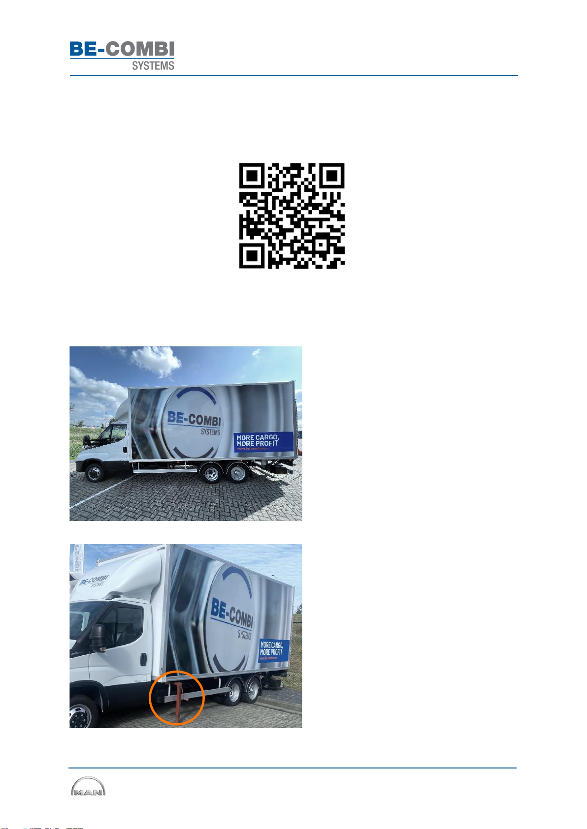
2.5 Connecting and disconnecting vehicle and trailer
The correct connecting and disconnecting procedure of vehicle and trailer are shown in detail in an
animation, accessible via the QR code or via the URL link below. The trailer is fit for purpose for the type
of vehicle and not exchangeable with any other type of vehicles.
www.be-combi.com/technical-documentation/videos
CAUTION! Images and animations may vary by type of vehicle and trailer.
•Vehicle and trailer are coupled here
•After docking, always check the following
procedures
•After coupling the vehicle and trailer, check
the removal of the left and right trailer support
User and Maintenance Manual MAN TGE
Page 9 of 31
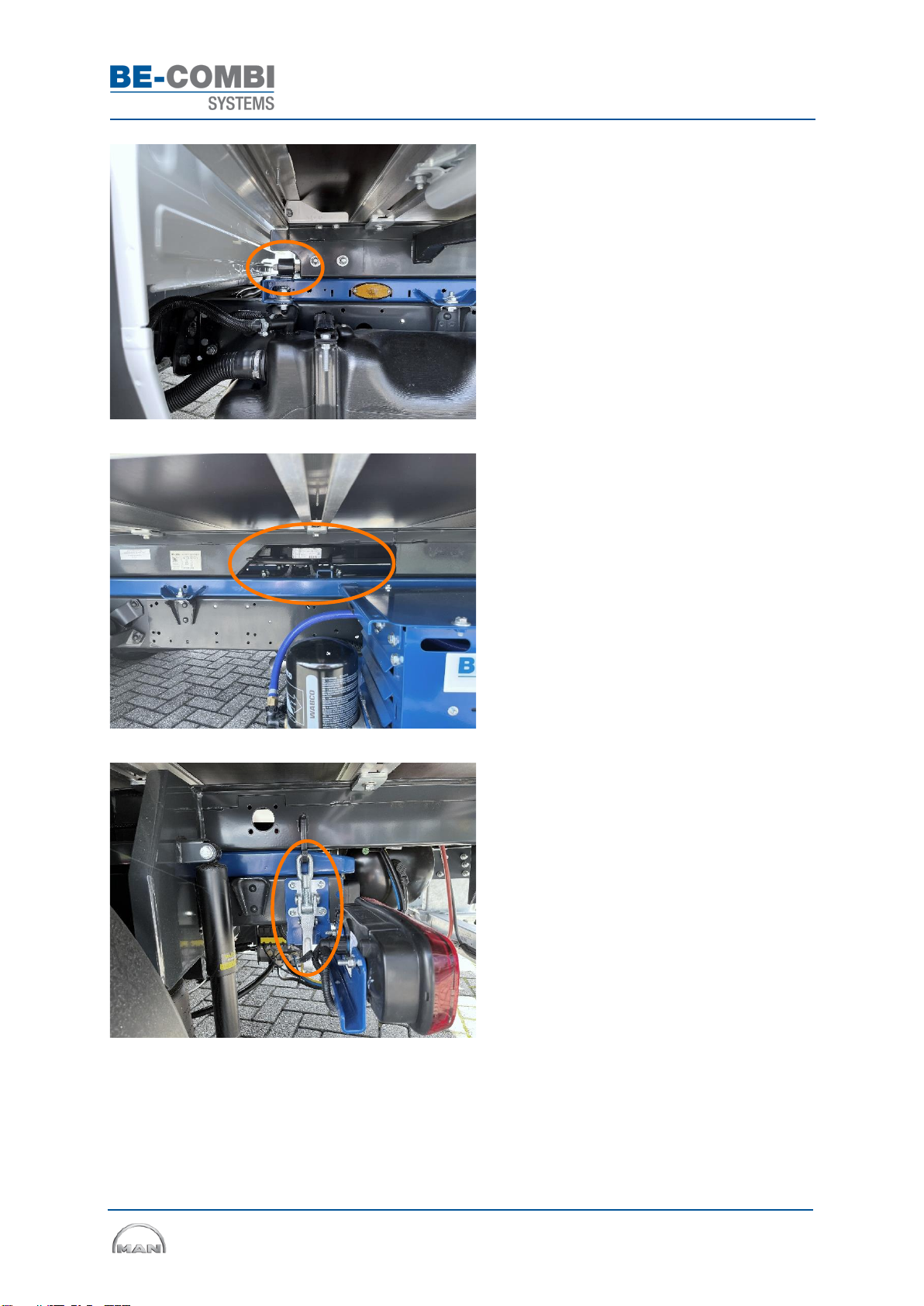
•After coupling, check whether the left and
right guide pins behind the vehicle cab are
correctly positioned in their guide rails
•Check that the fifth wheel lever on the
passenger side is fully retracted and secured
by the locking lever
•Check the left and right rear of the trailer for
correct positioning of hook clamps
User and Maintenance Manual MAN TGE
Page 10 of 31
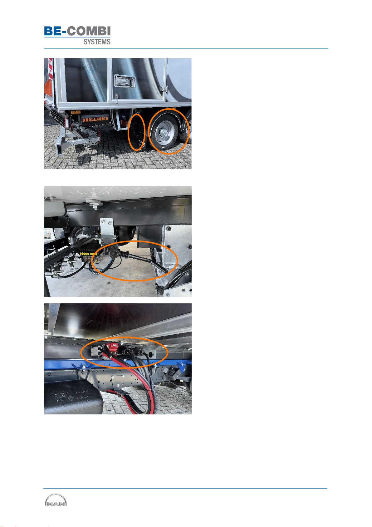
•Visually inspect the left and right trailer
wheels and wheel nuts for any damage or
incorrect mounting
•Visually check the left and right air bellows
and shock absorbers for cracks or leaks
•Check if the trailer parking brake is released,
operated by the spindle on the driver's side
•Check if all plugs are connected to the driver
or passenger side terminal board (depending
on model)
oDuomatic
o13-pin plug
oEBS plug
oTailgate Harrisson plug (optional)
oHeight control plug (optional)
oRear view camera (optional)

User and Maintenance Manual MAN TGE
Page 11 of 31
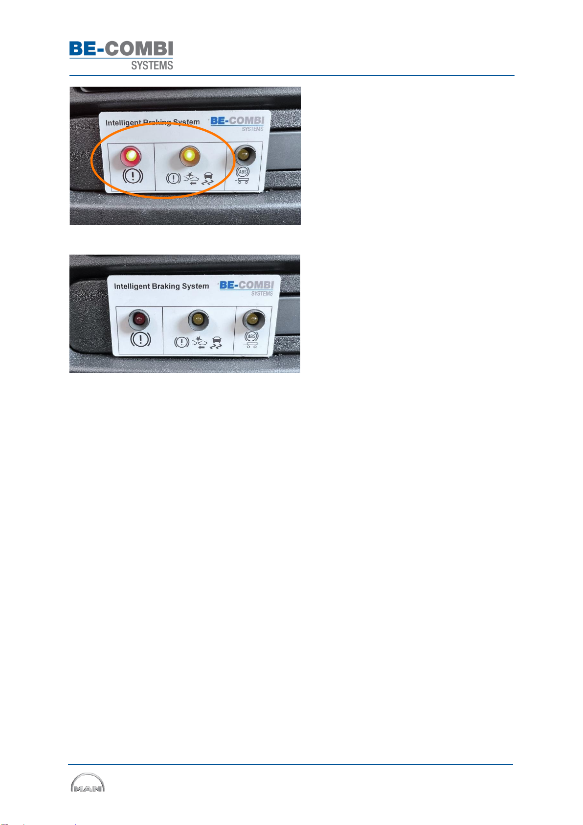
•Check the cabin dashboard control panel
whether IBS is fault free
•3x LED indicator when ignition switched on
•Short trailer brake operation is audible
•3x LED indicator should go out
•See also section 2.6.1
2.6 System description and instructions
This section describes the various systems with their associated instructions, which are present on the
3500PLUS System.
Intelligent Braking System (IBS) operation and display
The IBS ensures that the ESP, ABS, AEBS and ASR signals from the vehicle are transmitted to the trailer's
braking system for optimum safety. The system complies with the GSR2 regulations, which are in force
as of 07-07-2024.
•The IBS control panel is mounted on the
dashboard as shown.
•The IBS continuously performs a self-
diagnosis upon startup and while driving, any
malfunctions are displayed immediately.
•When ignition is turned on, 3x lights light up
briefly at the same time.
•The right ABS light is the diagnostic check
for the trailer brakes.
•If there is no fault, this light turns off
immediately or after reaching a speed of up to
10 km/h.
User and Maintenance Manual MAN TGE
Page 12 of 31
•The left red and centre orange lights light up
briefly, during this check the air brakes are
audibly operated briefly 1x.
•After this check, the lights go out.
•When operating correctly, all lights are off.
If a light stays on, there is a malfunction in the IBS, see also chapter 4:
•Red light - IBS malfunction where electronic brake control is converted to mechanical emergency
brake control. CAUTION! Semi-trailer remains braked at all times, however, with higher brake pedal
resistance. Consult your dealer immediately.
•Orange light centre - minor malfunction where IBS remains active. Consult dealer at first
opportunity.
•Orange light right - trailer brake failure. Semi-trailer brakes at maximum pressure using the back-
up system. Consult dealer at first opportunity.

User and Maintenance Manual MAN TGE
Page 13 of 31
Fifth wheel
•The fifth wheel provides the mechanical
coupling between the vehicle and trailer.
•The fifth wheel is positioned on the vehicle's
subframe.
•The fifth wheel is equipped with two levers.
oLocking lever - push it down to operate the
coupling lever.
oCoupling lever - pull out the coupling lever in
order to couple the trailer, see also section 2.5.
Park and brake valve
•The valve must be used to park the trailer
braked or unbraked when uncoupled from the
vehicle.
•The valve is positioned at the rear of the
trailer on the passenger’s side
oBlack button out Trailer brake fixed
(happens automatically when uncoupling)
oBlack button in Semi-trailer brake
released
•CAUTION! Never operate the black button if
the trailer is uncoupled on a slope, always use
the parking brake for this, see section2.6.4.
Older types of trailers are equipped with a different valve with an air-operated parking brake,
(additional red button).
oBlack button out Trailer brake fixed (happens automatically when uncoupling)
oBlack button in Semi-trailer brake released
oRed button out Parking brake fixed
oRed button in Parking brake released (must always be done manually with a
coupled and uncoupled trailer)

User and Maintenance Manual MAN TGE
Page 14 of 31
Semi-trailer parking brake
•Under normal operating conditions, the trailer
parking brake must not be used. The vehicle's
handbrake is powerful enough for a 7000 kg
combination on a steep slope.
•Only use the parking brake with the trailer
uncoupled on a steep slope
•The parking brake is positioned at the rear
end of the trailer on the driver’s side
•Turn the crank counterclockwise to activate
the parking brake
•Turn the crank clockwise to deactivate the
parking brake
User and Maintenance Manual MAN TGE
Page 15 of 31
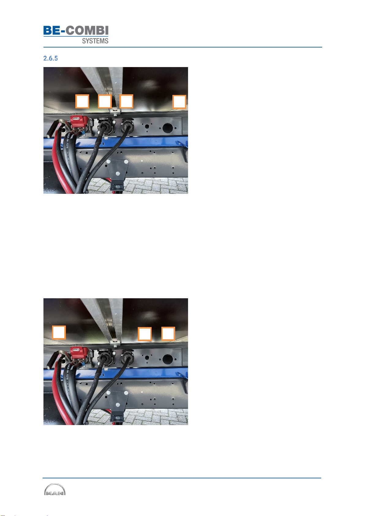
Plug connection terminal
•All plugs between the vehicle and trailer are
connected on the connection terminal on the
front of the trailer.
•Fixed connections:
1. Duomatic –provides supply pressure and
power steering air pressure. Open the red
cover and push the handle down. Then hook
the connection into the connection terminal
block. Check connection properly.
2.EBS plug –controls the anti-lock system.
Open valve and push plug in. Lock by metal
bracket.
3. 13-pin plug –controls the lights
Open the valve and turn the bayonet socket
clockwise until plug is pulled fully into the
socket.
4. Diagnostic EBS plug –is not connected.
Dealer uses this for failure analysis of the EBS
unit
•Optional connections
5. Harrisson plug –high current for e.g. tail
lift. Push plug straight into holder.
6. 3-pin plug –height control is controlled
from the cab. Open cover and push plug into
plug box, form-fitting (not shown in image).
7.Camera plug –power and signal for rear
view camera. Open cover and push plug into
power socket, form-fitting (not shown in
image).
1
2
3
3
5
6
7
4

User and Maintenance Manual MAN TGE
Page 16 of 31
Tail lift controls (optional)
•The tail lift controls are located on the rear
end and passenger side of the trailer
•Refer to the tail lift supplier's manual for the
proper operation
Trailer height controls (optional)
•With the height control, it is possible to vary
the loading floor height
•The height control can also act as a traction
control on slippery surfaces. Reducing the
trailer axle load adds more pressure on the
vehicle's driving axle
•Valve and instructions are positioned at the
rear end of the trailer on the driver’s side
•The vehicle is also equipped with a joystick
for operating height control from the cab
•Position MAN TGE: right side of driver's seat
oJoystick up - trailer axle up
oJoystick down - trailer axle down
•CAUTION! Height control only works while
stationary and up to 10 km/h
•Above 10 km/h, the axle automatically
returns to driving position
User and Maintenance Manual MAN TGE
Page 17 of 31
3MAINTENANCE MANUAL
The maintenance required on the 3500PLUS System is shown below.
•This manual only describes the 3500PLUS System. The vehicle should be serviced as specified by
the manufacturer.
•Regular maintenance should be carried out at least every six months.
•In accordance with local laws and regulations, the vehicle and trailer should be legally inspected at
regular intervals.
•Maintenance must be carried out by qualified personnel in accordance with the general applicable
safety and environmental regulations.
Period
Air system
Coupling
connection
Semi-trailer
axle
Brake
system
Air
suspension
First use
x
Every 6 months
x
x
x
x
x
Every 12 months
x
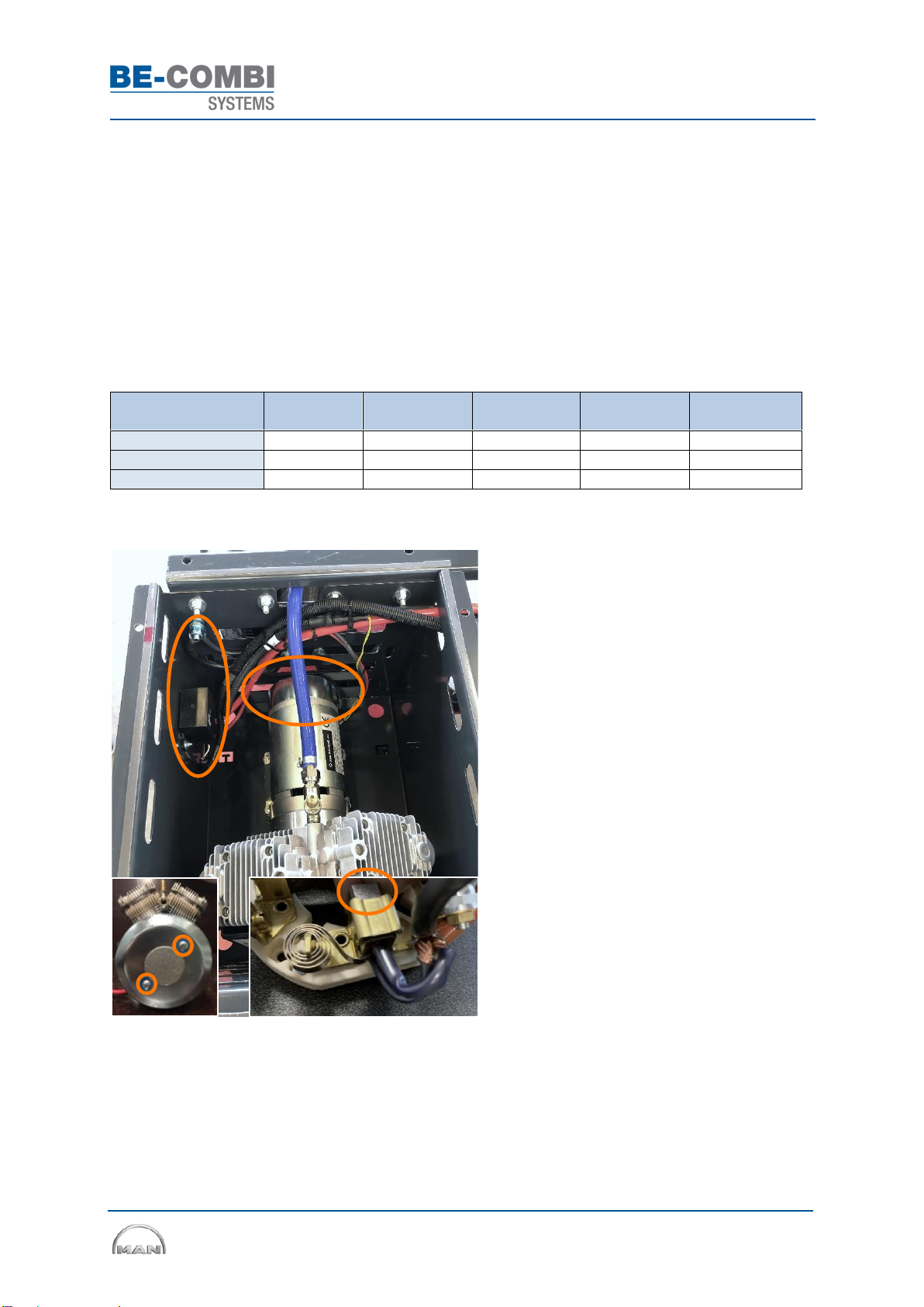
3.1 Air System
•Remove the cover of the compressor box, by
means of 4 bolts
•Remove the cover of the compressor motor,
by means of 2 screws
•Check the carbon brushes on the
compressor motor. Replace the carbon
brushes if the carbon brush length is the same
as the holder
•Check the wiring to the relay and the earth
point
•Check all air connections for leakages
User and Maintenance Manual MAN TGE
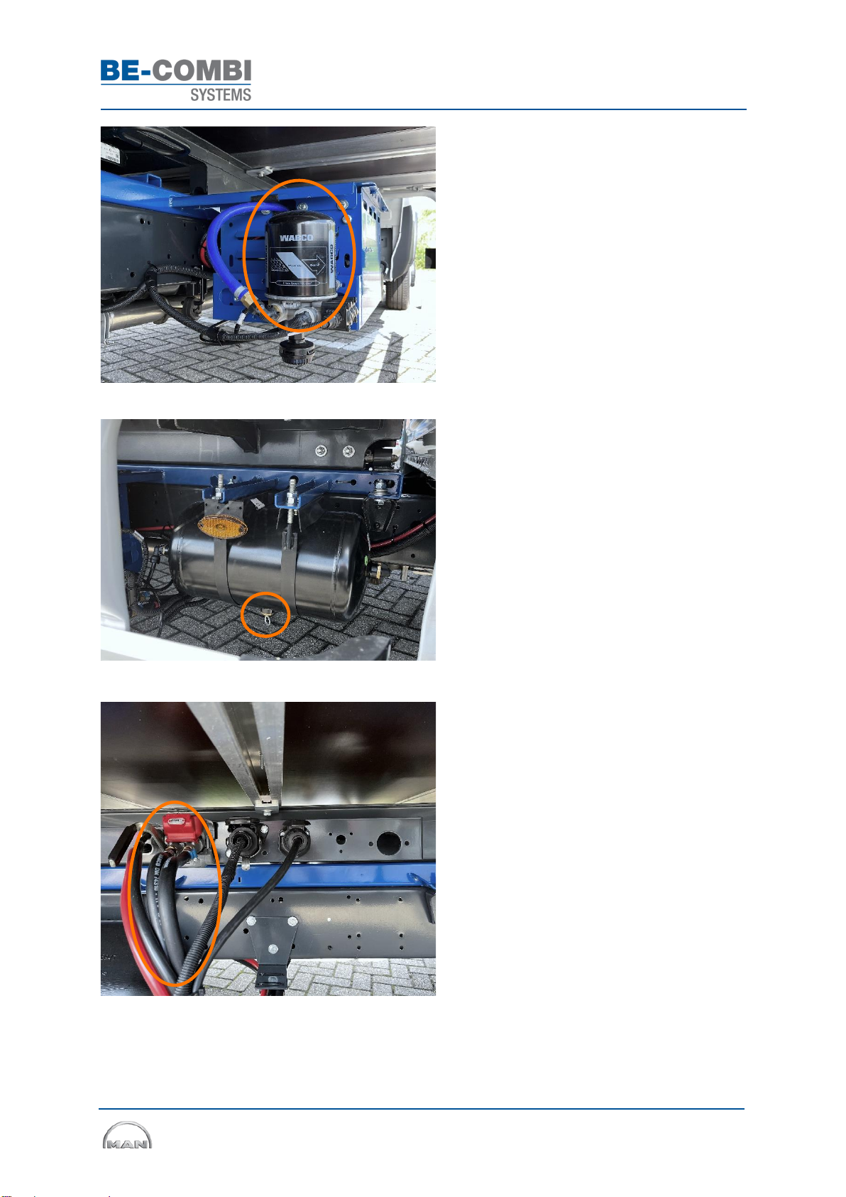
Page 18 of 31
•Replace annually the air dryer filter on the
outside of the compressor bin
•Disconnect the Duomatic to prevent deflation
of the trailer air system
•CAUTION! Remove full air pressure from
vehicle system, via air tank drain valve plug
•Remove the air filter
•Apply grease to the rubber O-ring
•Install new air filter hand-tight (15 Nm)
•Drain water at the 3x air tanks
•Pull ring to the left or right until no more
water comes out
•Check air tanks and brackets for corrosion
and replace if necessary
o2x air tank trailer
o1x air tank vehicle
•Check all rubber air hoses for cracks and
leaks
•Replace if necessary
User and Maintenance Manual MAN TGE
Page 19 of 31
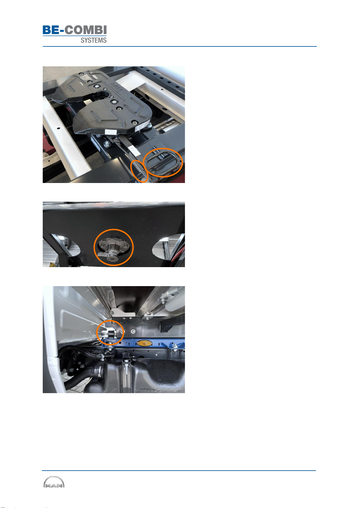
3.2 Coupling connection
•Check the bolt connection of the fifth wheel
on the subframe. Tightening torque 260 Nm
•Apply graphite grease on the entire top side
of the fifth wheel
•Check the kingpin bolt connection.
Tightening torque 130 Nm
•Lubricate the pin on the front left and right
sides of the fifth wheel with ceramic grease
User and Maintenance Manual MAN TGE
Page 20 of 31
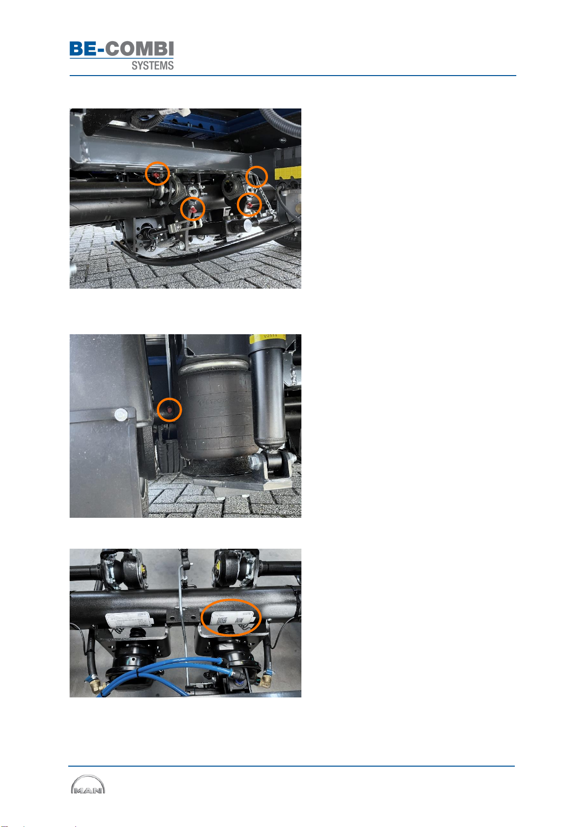
3.3 Semi-trailer axle
•Lubricate the axle with high pressure grease
(EP)
•Pump grease into grease nipple 6x until
grease is flowing out the axle
oAnchor plate, left and right sides (2x)
oSlack adjusters, left and right sides (4x)
•Position of grease nipple on anchor plate, left
and right sides
•Scan the QR code on the Gigant axle for the
correct maintenance manual
This manual suits for next models
2
Table of contents
Popular Automobile Accessories manuals by other brands


Whelen Engineering Company
Whelen Engineering Company Howler installation guide

GMC
GMC AUX-GM3 GM CLASS II Quick start installation guide

Parrot
Parrot SAT-3500 user manual

Hook
Hook E063 quick start guide

ClearView
ClearView EXPANDA EXP-01 Assembly instructions

TEINHOF
TEINHOF B-042 FITTING AND OPERATION MANUAL