manuals.online logo
Brands
  1. Home
  2. •
  3. Brands
  4. •
  5. Fortin
  6. •
  7. Automobile Accessories
  8. •
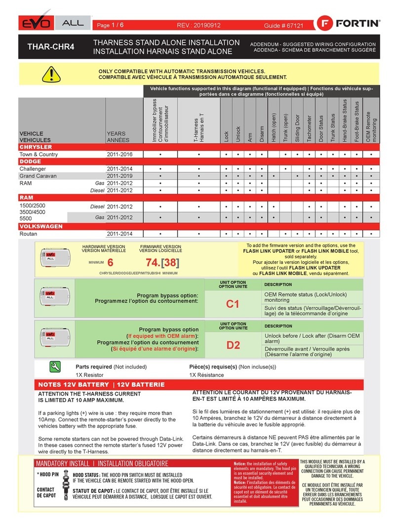
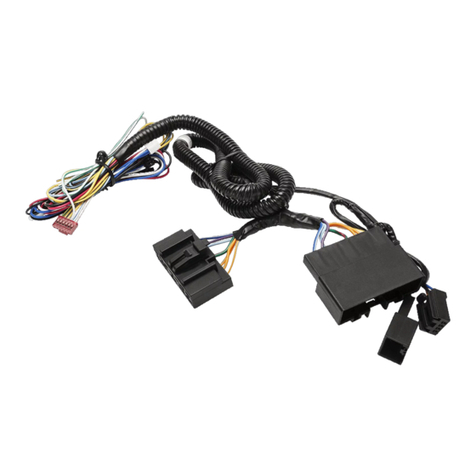
  9. Fortin EVO ONE THAR-GM7 User manual

Fortin EVO ONE THAR-GM7 User manual

1-Page_entete
WARNING
ATTENTION
A11 OFF
NON
*
HOOD
PIN
HOOD STATUS : THE HOOD PIN SWITCH (INCLUDED)
MUST BE INSTALLED IF THE VEHICLE CAN BE
REMOTE STARTED WITH THE HOOD OPEN, SET FUNCTION A11 TO OFF.
CONTACT
DE CAPOT
SECURITY STICKER
AUTOCOLLANT DE
SÉCURITÉ
MANDATORY INSTALL | INSTALLATION OBLIGATOIRE Notice: the installation of safety
elements are mandatory. The hood pin
and the sticker are essential security
elements and must be installed.
Notice: l'installation des éléments de
sécurité est obligatoire. Le contact de
capot et l'autocollant de sécurité sont
des éléments de sécurité essentiels et
doivent absolument être installés.
THIS MODULE MUST BE INSTALLED BY A
QUALIFIED TECHNICIAN. A WRONG
CONNECTION CAN CAUSE PERMANENT
DAMAGE TO THE VEHICLE.
CE MODULE DOIT ÊTRE INSTALLÉ PAR
UN TECHNICIEN QUALIFIÉ, TOUTE
ERREUR DANS LES BRANCHEMENTS
PEUT OCCASIONNER DES DOMMAGES
PERMANENTS AU VÉHICULE.
STATUT DE CAPOT : LE CONTACT DE CAPOT (INCLUS), DOIT ÊTRE
INSTALLÉ SI LE VÉHICULE PEUT DÉMARRER À DISTANCE, LORSQUE LE
CAPOT EST OUVERT, PROGRAMMEZ LA FONCTION A11 À NON.
Included
Inclus
ONE REV.: 20211021
ADDENDUM - SUGGESTED WIRING CONFIGURATION
ADDENDA - SCHÉMA DE BRANCHEMENT SUGGÉRÉ
Contents
Supported functions & Function programming | Fonctions supportées et programmation des fonctions—1
Photo & Location | Photos & Emplacements—3
WIRE TO WIRE Connection Diagram - Automatic Transmission | Diagramme de Branchements FIL À FIL - Transmission Automatique—4
WIRE TO WIRE Connection Diagram - Manual Transmission | Diagramme de Branchements FIL À FIL - Transmission Manuelle—5
THAR-GM7 - THarness Diagram- Automatic Transmission | Diagramme harnais en T- Transmission Automatique—6
THAR-GM7 - THarness Diagram- Manual Transmission | Diagramme harnais en T- Transmission Manuelle—7
Key Bypass Programming Procedure | Procédure de Programmation Contournement de Clé—8
Remote starter programming procedure | Remote starter functionality | Procédure de programmation du démarreur à dis-
tance | Fonctionalité du démarreur à distance—10
Disclaimer | Avertissement—12
Program remote
starter option for R.S. OEM
REMOTE STAND ALONE:
Programmez l’option
démarreur à distance pour
TÉLÉCOMMANDE D’ORIGI-
NE STAND ALONE:
FUNCTION
FONCTION MODE DESCRIPTION
38 2Enable : Press 3x Lock to remote start with the OEM remote.
Activé : Appuyez x3 sur Verrouille de la télécommance d’origine
pour démarrer à distance le véhicule.
The vehicles Flip-key remote will not be
functional during remote start.
La télécommande Flip-key du véhicule ne sera pas fonctionnelle durant
le démarrage à distance.
BYPASS FIRMWARE VERSION
VERSION LOGICIELLE CONTOURNEMENT
To add the rmware version and the options, use the
FLASH LINK UPDATER or FLASH LINK MOBILE tool,
sold separately.
Pour ajouter la version logicielle et les options,
utilisez l’outil FLASH LINK UPDATER
ou FLASH LINK MOBILE, vendu séparément.
70.[41]
GM MINIMUM
Parts required (Not
included)
Pièce(s) requise(s) (Non
incluse(s)) PAGE
WIRE TO WIRE DIAGRAM | SCHÉMA DE BRANCHEMENTS FIL À FIL
AUTOMATIC TRANSMISSION
TRANSMISSION AUTOMATIQUE 1X 2 Amp Fuse 1X Fusible 2 Amp Page 4
MANUAL TRANSMISSION
TRANSMISSION MANUELLE
1X 2 Amp Fuse
1X 180 Ohm resistor
1X Fusible 2 Amp
1X Résistance 180 Ohm Page 5
THARNESS DIAGRAM | SCHÉMA DE BRANCHEMENTS HARNAIS EN T
THARNESS THAR-GM7 AUTOMATIC TRANSMISSION
TRANSMISSION AUTOMATIQUE 1x THAR-GM7 1x THAR-GM7 Page 6
THARNESS THAR-GM7 MANUAL TRANSMISSION
TRANSMISSION MANUELLE
1x THAR-GM7
1x 180 ohm resistor
1x THAR-GM7
1x Résistance 180 Ohm Page 7
REGULAR AND THAR-GM7 THARNESS INSTALLATION
INSTALLATION RÉGULIÈRE ET HARNAIS THAR-GM7
Guide # 100211
Vehicle functions supported in this diagram (functional if equipped) | Fonctions du véhicule supportées dans ce diagramme (fonction-
nelles si équipé)
VEHICLE
VEHICULES
YEARS
ANNÉES
Immobilizer bypass
Contournement
d’immobilisateur
Lock
Unlock
Arm
Disarm
Trunk (open)
RAP Disable
Tachometer
Door Status
Trunk Status
Hood Status*
Hand-Brake Status
Foot-Brake Status
PK3, Passlock
OEM remote Monitoring**
R.S. OEM remote
Stand Alone compatible
CHEVROLET
Cruze
Flip-key
2010-2015
•
•
•
•
•
•
•
•
•
•
•
•
•
•
•
•
Cruze Limited
Flip-key
2016
•
•
•
•
•
•
•
•
•
•
•
•
•
•
•
•
Supported functions & Function programming | Fonctions supportées et programmation des
fonctions
Page 1 / 12
3.1-NOTES
This guide may change without notice. See www.fortin.ca for latest version.
Ce guide peut faire l’objet de changement sans préavis. Voir www.fortin.ca pour la récente version.
NOTES
Program bypass option:
Programmez l’option du contournement:
UNIT OPTION
OPTION UNITE DESCRIPTION
C1
OEM Remote status (Lock/Unlock)
monitoring
Suivi des status (Verrouillage/Déverrouil-
lage) de la télécommande d’origine
ATTENTION!
Date: xx-xx
REMOTE STARTER & ALARM
& BYPASS MODULE
Made in Canada
Démarreur à Distance, Alarme & Bypass
Waranty void if opened
Service No : X
www.fortinbypass.com
Starter : X
EVO-ONE : X
EVO-ONE
DATE: XX-XX
E5
OFF
NON By default DEACTIVATED
Par defaut DÉSACTIVÉ
ON
OUI
MANUFACTURED MODULES
BETWEEN: 04/2018 TO 04/2019
MODULES MANUFACTURÉS
ENTRE: 04/2018 AU 04/2019
Program bypass option
(If equiped with OEM alarm):
Programmez l’option du contournement
(Si équipé d’une alarme d’origine):
D2
Unlock before / Lock after (Disarm OEM
alarm)
Déverrouille avant / Verrouille après
(Désarme l’alarme d’origine)
Program bypass option
IF THE VEHICLE IS NOT EQUIPPED
WITH FUNCTIONAL HOOD PIN:
Programmez l’option du contournement
SI LE VÉHICULE N’EST PAS ÉQUIPÉ
D’UN CONTACT DE CAPOT FONCTIONNEL:
UNIT OPTION
OPTION UNITE DESCRIPTION
A11 OFF
NON
Hood trigger (Output Status).
Contact de capot (état de sortie).
Page 2 / 12
This guide may change without notice. See www.fortin.ca for latest version.
Ce guide peut faire l’objet de changement sans préavis. Voir www.fortin.ca pour la récente version.
DESCRIPTION |DESCRIPTION
1 2 34
8
9 10 11 12 13 14
15 18 19 20
21 24 25 26
56 7
16 17
23
22
8
9 10 11 12 13 14 15
24 25 26 27
567
22 23
18 19 20 21
16 17
1234
8 9 10 11 12 13 14
15 16 17 18 19 20
21 22 23 24 25
13457
26
BCM - Central Console, Passenger side
BCM - Console Centrale, Côté passager
(~) IMMO
DATA (MUX)
PASSLOCK
(+) IGNITION
(~) SWC
(+) 12V
(+)ACCESSORY
(-) PARKING
LIGHTS
AT BCM
AU BCM
Photo & Location | Photos & Emplacements
Page 3 / 12
Yellow In A1
Purple Out A2
Purple/White Out A3
Green Out A4
White Out A5
Orange Out A6
Orange/Black Out A7
Dk.Blue Out A8
Red/Blue In A9
Lt.Blue/Black In/Out A10
Black In A11
Pink Out A12
Yellow/Black Out A13
Brown/White In A14
Pink/Black In A15
Purple/Yellow In/Out A16
Green/White In/Out A17
Green/Red In/Out A18
White/Black Out A19
Lt.Blue In/Out A20
C5 Brown
C4 Gray/Black
C3 Gray
C2 Orange/Brown
C1 Orange/Green
D6 White/Red
D5 White/Blue
D4 White/Green
D3 Yellow/Red
D2 Yellow/Blue
D1 Yellow/Green
White Out E1
Orange Out E2
Red In E3
Black In E4
Pink In/Out E5
Yellow Out E6
This guide may change without notice. See www.fortin.ca for latest version.
Ce guide peut faire l’objet de changement sans préavis. Voir www.fortin.ca pour la récente version.
CUT LOOP FOR AUTOMATIC
TRANSMISSION MODE.
COUPEZ LA BOUCLE POUR LE
MODE TRANSMISSION
AUTOMATIQUE.
AUTOMATIC TRANSMISSION WIRING CONNECTION |SCHÉMA DE BRANCHEMENT TRANSMISSION AUTOMATIQUE
HOOD PIN
MANDATORY
CONTACT CAPOT
OBLIGATOIRE
(-) Hood pin
(-)Ground
(+)12V
(-)Parking Lights
(+)Ignion
A2
A3
A4
A5
A6
A7
A8
A9
A10
A11
A12
A13
A14
A15
A16
A17
A18
A19
A20
E1
E2
E3
E4
E5
E6
C5
C4
C3
C2
C1
D6
D5
D4
D3
D2
D1
A1
D1
D5
C1
C2
C3
C4
E6
E5
E2
E1
A19
A17
A16
A14
A13
A11
A8
A7
A6
A5
A4
A3
A2
Gray/Black
Gris/Noir White/Purple
Blanc/Mauve
Purple/Black
Mauve/Noir Green
Vert
Red/Gray
Rouge/Gris
CRUZE
CRUZE LIMITED
BCM - Central
Console,
Passenger side
BCM - Console
Centrale,
Côté passager
Lt. Green/Purple
Vert Pâle/Mauve Green/Gray
Vert/Gris
(~)CAN SW
(~)Immo Data
(~)Immo Data
(+)Igni�on
(+)12V
(MUX)Passlock
(~)Immo Power
(~)Immo Power
(~)Immo Power
D3/A1
D3/A1
E3/D2
E3/D2
A12
A20
Ground
2 Amp
Fuse
Fusible
Back view
27-Pin Blue
Connector
At BCM
Vue de dos
Connecteur Bleu
de 27-Pins
Au BCM
Back view
25-Pin Green
Connector
At BCM
Vue de dos
Connecteur Vert
de 25-Pins
Au BCM
Back view
26-Pin White
Connector
At BCM
Vue de dos
Connecteur Blanc
de 26-Pins
Au BCM
1 2 34
8
9 10 11 1213 14
15 18 19 20
21 24 25 26
56 7
16 17
23
22
8
9 10 11 12 13 14 15
24 25 26 27
567
22 23
18 19 20 21
16 17
1234
8 9 10 11 12 13 14
15 16 17 18 19 20
21 22 23 24 25
13457
26
10
4
5
6
7
8
9
19
20
21
17
16
14
15
13
12 18
11
25
24
23
22
1
2
3
10
4
5
6
7
8
9
19
20
21
17
16
14
15
13
12 18
11
27
25
24
23
22
26
1
2
3
10
4
5
6
7
8
9
19
20
21
17
16
14
15
13
12
1811
25
24
23
22
26
1
2
3
CUT
(~) IMMO
DATA (~) IMMO
POWER (MUX)
PASSLOCK (+)
12V (~)
SWC (-) PARKING
LIGHTS
D4
A10/A20 A18 C5
A9/D6
(+)
IGNITION
6
WIRE TO WIRE Connection Diagram - Automatic Transmission | Diagramme de Branchements FIL À FIL - Transmission Automatique
Page 4 / 12
Yellow In A1
Purple Out A2
Purple/White Out A3
Green Out A4
White Out A5
Orange Out A6
Orange/Black Out A7
Dk.Blue Out A8
Red/Blue In A9
Lt.Blue/Black In/Out A10
Black In A11
Pink Out A12
Yellow/Black Out A13
Brown/White In A14
Pink/Black In A15
Purple/Yellow In/Out A16
Green/White In/Out A17
Green/Red In/Out A18
White/Black Out A19
Lt.Blue In/Out A20
C5 Brown
C4 Gray/Black
C3 Gray
C2 Orange/Brown
C1 Orange/Green
D6 White/Red
D5 White/Blue
D4 White/Green
D3 Yellow/Red
D2 Yellow/Blue
D1 Yellow/Green
White Out E1
Orange Out E2
Red In E3
Black In E4
Pink In/Out E5
Yellow Out E6
This guide may change without notice. See www.fortin.ca for latest version.
Ce guide peut faire l’objet de changement sans préavis. Voir www.fortin.ca pour la récente version.
MANUAL TRANSMISSION WIRING CONNECTION |SCHÉMA DE BRANCHEMENT TRANSMISSION MANUELLE
HOOD PIN
MANDATORY
CONTACT CAPOT
OBLIGATOIRE
(-) Hood pin
(+)Ignion
(-)Ground
(+)12V
(-)Parking Lights
(+)Ignion
A2
A3
A4
A5
A6
A7
A8
A9
A10
A11
A12
A13
A14
A15
A16
A17
A18
A19
A20
E1
E2
E3
E4
E5
E6
C5
C4
C3
C2
C1
D6
D5
D4
D3
D2
D1
A1
D1
D5
C1
C2
C3
C4
E6
E2
E1
A19
A17
A16
A14
A13
A11
A8
A7
A6
A4
A3
A2
Gray/Black
Gris/Noir White/Purple
Blanc/Mauve
Purple/Black
Mauve/Noir Green
Vert
Red/Gray
Rouge/Gris
CRUZE
CRUZE LIMITED
Lt. Green/Purple
Vert Pâle/Mauve Green/Gray
Vert/Gris Yellow
Jaune
BCM - Central
Console,
Passenger side
BCM - Console
Centrale,
Côté passager
(~)CAN SW
(~)Immo Data
(~)Immo Data
(+)Igni�on
(+)12V
(MUX)Passlock
(~)Immo Power
(~)Immo Power
(~)Immo Power
D3/A1
D3/A1
E3/D2
E3/D2
A12
A20
Ground
2 Amp
Fuse
Fusible
180 ohm
Resistor
A5
(-)Clutch
1A Diode
Back view
27-Pin Blue
Connector
At BCM
Vue de dos
Connecteur Bleu
de 27-Pins
Au BCM
Back view
25-Pin Green
Connector
At BCM
Vue de dos
Connecteur Vert
de 25-Pins
Au BCM
Back view
26-Pin White
Connector
At BCM
Vue de dos
Connecteur Blanc
de 26-Pins
Au BCM
1 2 34
8
9 10 11 1213 14
15 18 19 20
21 24 25 26
56 7
16 17
23
22
8
9 10 11 12 13 14 15
24 25 26 27
567
22 23
18 19 20 21
16 17
1234
8 9 10 11 12 13 14
15 16 17 18 19 20
21 22 23 24 25
13457
26
10
4
5
6
7
8
9
19
20
21
17
16
14
15
13
12 18
11
25
24
23
22
1
2
3
10
4
5
6
7
8
9
19
20
21
17
16
14
15
13
12 18
11
27
25
24
23
22
26
1
2
3
10
4
5
6
7
8
9
19
20
21
17
16
14
15
13
12
1811
25
24
23
22
26
1
2
3
CUT
(~) IMMO
DATA (~) IMMO
POWER (MUX)
PASSLOCK (+)
12V (~)
SWC (-) PARKING
LIGHTS
D4
A10/A20 A18 C5
A9/D6
(+)
IGNITION
6
1 32
Back view -
3-Pin Black
Connector - At
Switch
Vue de dos -
Connecteur Noir
de 3-Pins - Au
commutateur
(-) CLUTCH
WIRE TO WIRE Connection Diagram - Manual Transmission | Diagramme de Branchements FIL À FIL - Transmission Manuelle
Page 5 / 12

Other manuals for EVO ONE THAR-GM7

2

Other Fortin Automobile Accessories manuals

Fortin EVO ONE User manual

Fortin

Fortin EVO ONE User manual

Fortin EVO-ALL User manual

Fortin

Fortin EVO-ALL User manual

Fortin EVO ALL User manual

Fortin

Fortin EVO ALL User manual

Fortin TB-SUBARU2 User manual

Fortin

Fortin TB-SUBARU2 User manual

Fortin EVO-ONE User manual

Fortin

Fortin EVO-ONE User manual

Fortin EVO ONE User manual

Fortin

Fortin EVO ONE User manual

Fortin THAR-CHR3 User manual

Fortin

Fortin THAR-CHR3 User manual

Fortin Evo All THAR-CHR4 User manual

Fortin

Fortin Evo All THAR-CHR4 User manual

Fortin EVO ALL User manual

Fortin

Fortin EVO ALL User manual

Fortin EVO-ALL User manual

Fortin

Fortin EVO-ALL User manual

Fortin EVO KEY User manual

Fortin

Fortin EVO KEY User manual

Fortin EVO-ONE User manual

Fortin

Fortin EVO-ONE User manual

Fortin EVO-CAN User manual

Fortin

Fortin EVO-CAN User manual

Fortin THAR-AUD1 User manual

Fortin

Fortin THAR-AUD1 User manual

Fortin EVO ALL User manual

Fortin

Fortin EVO ALL User manual

Fortin EVO ONE User manual

Fortin

Fortin EVO ONE User manual

Fortin EVO ALL User manual

Fortin

Fortin EVO ALL User manual

Fortin PATS 1 User manual

Fortin

Fortin PATS 1 User manual

Fortin PATS-GM User manual

Fortin

Fortin PATS-GM User manual

Fortin EVO-GMT1 User manual

Fortin

Fortin EVO-GMT1 User manual

Fortin Evo One THAR-VW6 User manual

Fortin

Fortin Evo One THAR-VW6 User manual

Fortin EVO-ALL User manual

Fortin

Fortin EVO-ALL User manual

Fortin EVO ALL User manual

Fortin

Fortin EVO ALL User manual

Fortin Evo One THAR-FOR1 User manual

Fortin

Fortin Evo One THAR-FOR1 User manual

Popular Automobile Accessories manuals by other brands

Magneti Marelli AC161 Installation instruction

Magneti Marelli

Magneti Marelli AC161 Installation instruction

FDI uEZ GUI Start here

FDI

FDI uEZ GUI Start here

JCROffroad JT Install instructions

JCROffroad

JCROffroad JT Install instructions

Rostra VOXXElectronics 250-1930 owner's guide

Rostra

Rostra VOXXElectronics 250-1930 owner's guide

TOP VEHICLE TECH GR3FORD5 installation manual

TOP VEHICLE TECH

TOP VEHICLE TECH GR3FORD5 installation manual

Safe Fleet PRIME DESIGN AR-2000-BLK manual

Safe Fleet

Safe Fleet PRIME DESIGN AR-2000-BLK manual

Skoda Fabia Combi 5J Fitting instructions

Skoda

Skoda Fabia Combi 5J Fitting instructions

Camcar 40077 Al Mounting instructions

Camcar

Camcar 40077 Al Mounting instructions

Camcar 40089 AL Mounting instructions

Camcar

Camcar 40089 AL Mounting instructions

Impac Tradesman 2000 installation manual

Impac

Impac Tradesman 2000 installation manual

DVB OFFROAD BRSB-01 installation manual

DVB

DVB OFFROAD BRSB-01 installation manual

Safari Snorkel SS385HF installation guide

Safari Snorkel

Safari Snorkel SS385HF installation guide

ULTIMATE SPEED 279746 Assembly and Safety Advice

ULTIMATE SPEED

ULTIMATE SPEED 279746 Assembly and Safety Advice

SSV Works DF-F65 manual

SSV Works

SSV Works DF-F65 manual

ULTIMATE SPEED CARBON Assembly and Safety Advice

ULTIMATE SPEED

ULTIMATE SPEED CARBON Assembly and Safety Advice

Witter F174 Fitting instructions

Witter

Witter F174 Fitting instructions

WeatherTech No-Drill installation instructions

WeatherTech

WeatherTech No-Drill installation instructions

TAUBENREUTHER 1-336050 Installation instruction

TAUBENREUTHER

TAUBENREUTHER 1-336050 Installation instruction

manuals.online logo
manuals.online logoBrands
  • About & Mission
  • Contact us
  • Privacy Policy
  • Terms and Conditions

Copyright 2025 Manuals.Online. All Rights Reserved.