4
operating instructions
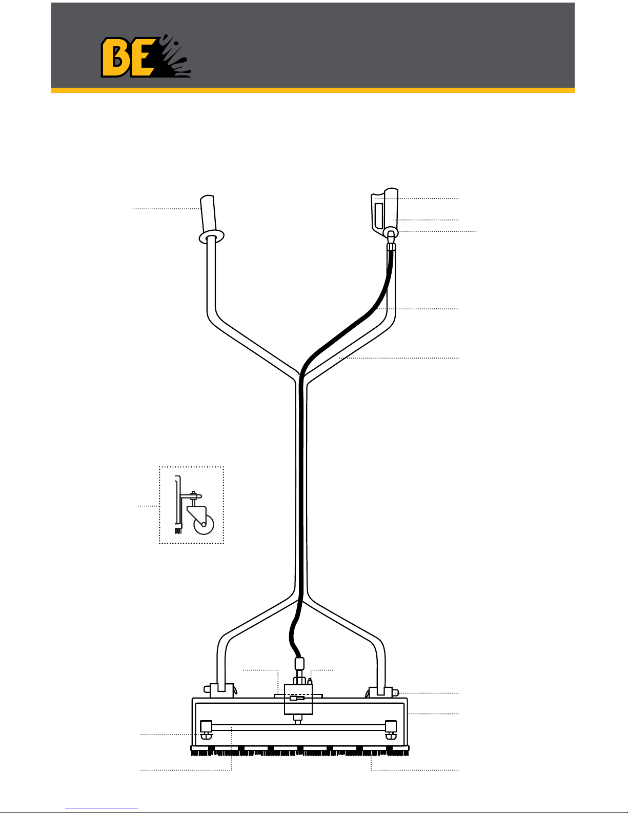
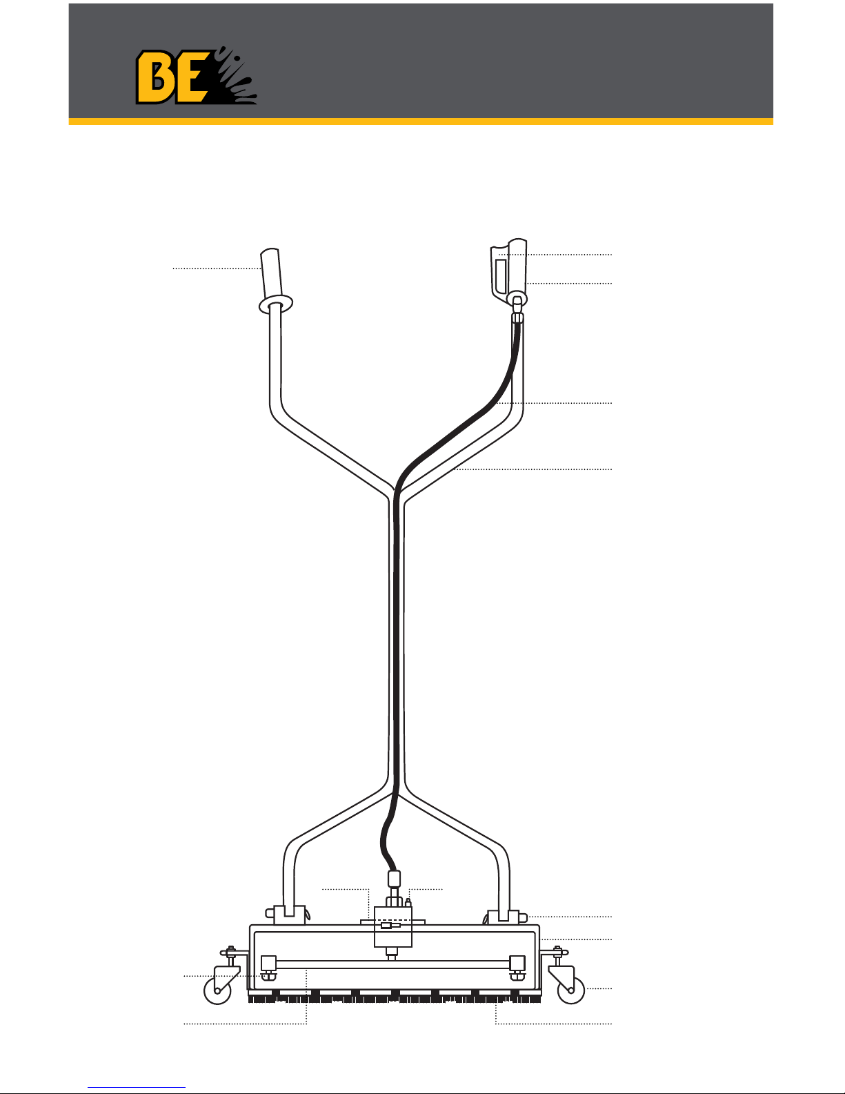
Set-Up
1. Fit the lower portion of the handle into the mounting brackets on the
cover and secure with the bolts or the pins & clips.
2. Next, tighten the “fixed” hose end into the gun mounted onto the upper
portion of the handle. Use teflon tape on the hose ends.
3. Once this is complete, join the two sections of the handle together and
secure with the bolt or the pin & clip. Tighten the swivel end of the
hose into the top of the rotary head.
4. Turn the cover over and check to ensure that the nozzle tips are
securely tightened and the spray pattern is in line with the rotary arm.
5. It is important to adjust and tighten the rotary head so the rotary arm
spray tips are a minimum of 1” distance from the surface being
cleaned.
Operation
The Surface Cleaning System you have purchased connects directly to
your high pressure hose and pressure washer by means of quick cou-
plers, operating to a maximum of 4000 PSI.
This Whirl-a-Way is designed to operate with both hot & cold water pres-
sure washers. We do not recommend the use of hot water as the nylon
brush skirt will soften and wear prematurely, voiding any warranty.
We recommend that you supply grease to the rotary head every 30 – 40
hours of use.
During operation, should you experience a buildup of small stones or
other foreign material within the cover, we recommend that you simply tip
the cleaner on its side at 45° which should expel any foreign materials.
This will give longer wear to your tips and swivel arm.
The tips that have been installed on your surface cleaning system per-
mit the use of your cleaner with a pressure washer producing up to 7
GPM at 4000 PSI. Higher GPM tips should be installed if your pres-
sure washer has a higher GPM/PSI rating. Periodically check the tips to
ensure they are not plugged by dirt particles.
It is very important when operating your Whirl-a-Way, that you maintain a
continuous motion. Should you leave the cleaner in a stationary position,
the surface being cleaned can be seriously damaged by the high pres-
sure. The distance of the nozzle tips from the surface can be adjusted by
loosening the bolt on the rotary head mounting collar and adjusting the
rotary head up or down. Be certain the allen head bolt is tightened again
to prevent the rotary head from moving during operation. Please ensure
that your rotary head is adjusted to maintain a minimum of 1” clearance