BeaconMedaes 4107 9027 47.00 Manual

Installation, Operation and Maintenance Instructions
Ohmeda Retrofit Gas Control Panel
Part number 4107 9027 47.00
March 16, 2020


Installation, Operation and Maintenance Manual
Wall Mount Gas Control Panel
Part number 4107 9027 47.00
05 March 2020
This unit is purchased from:
Date purchased:
Model number:
Option(s) included:
Any information, service or spare parts requests should include the unit model number and be
directed to:
BeaconMedæs
1059 Paragon Way,
Rock Hill, SC 29730
Phone: (803) 817-5600
Fax: (803) 817-5750
www.beaconmedaes.com
BeaconMedæs reserves the right to make changes and improvements to update products sold
previously without notice or obligation.


Table of Contents
1. Introduction ....................................................................... 1
1.1 Audience ......................................................................................................................1
1.2 Abbreviations ..............................................................................................................1
1.3 Definition of Statements............................................................................................1
1.4 Environmental Declarations......................................................................................1
1.5 About Gas Control Panels..........................................................................................1
2. Removal of Old Panel....................................................... 2
2.1 Remove Ohmeda Front Panel...................................................................................2
3. Installing New Panel .......................................................... 2
3.1 Installing Retrofit Kit...................................................................................................2
4. Testing................................................................................. 3
4.1 Testing Instructions ....................................................................................................3
4.2 Operating Instructions ...............................................................................................3
5. Maintenance....................................................................... 4
5.1 Maintenance Instructions..........................................................................................4


1.1 Audience
This manual provides information related to the
installation and operation of the Retrofit Ohmeda
Gas Control Panel system manufactured by
BeaconMedæs. Service information contained in
this manual is intended for use by technicians or
personnel qualified to repair and service medical
gas equipment.
1.2 Abbreviations
CGA Compressed Gas Association
FNPT Female National Pipe Thread
MNPT Male National Pipe Thread
PSIG Pounds Per Square Inch- Gauge
DISS Diameter-Index Safety System
1.3 Definition of Statements
Statements in this manual preceded by
following words are of special significance.
WARNING: Means there is a possibility of
injury or death to yourself or others.
CAUTION: Means there is a possibility of
damage to unit or other property.
NOTE: Indicates points of particular interest for
more efficient and convenient operation.
1.4 Environmental Declarations
When developing products and services,
BeaconMedæs tries to understand, address, and
minimize the negative environmental effects
that the products and services may have, when
being manufactured, distributed, and used, as
well as at their disposal.
Recycling and disposal policies are part of the
development of all BeaconMedæs products.
BeaconMedæs company standards determine
strict requirements.
When selecting materials, the substantial
recyclability, the disassembly possibilities and
the separability of the materials and assemblies
are considered as well as the environmental
perils and dangers to health during the recycling
and disposal of the unavoidable rates of non-
recyclable materials.
BeaconMedæs products for the most part
consist of metallic materials that can be
remelted in steelworks and smelting works and
that is therefore almost infinitely recyclable. The
plastic use is labeled; sorting and fractioning
of the materials for recycling in the future is
foreseen.
Disposal of Materials
Dispose contaminated substances and materials
separately, according to local applicable
environmental legislations.
Dispose all components according to the
applicable disposal regulations.
1. Introduction
NOTE:
This concept can only succeed with your help.
Support us by disposing professionally.
By assuring a correct disposal of the product
you help to prevent possible negative
consequences for environment and health
that can occur with inappropriate waste
handling.
Recycling and re-usage of materials helps to
preserve natural resources.
1.5 About Gas Control Panels
BeaconMedaes Wall Mount Panels
The BeaconMedaes gas control panel is designed
to update old style Ohmeda control panels sold
prior to 1996 (0221-5126-800). The kit contains
all required parts and can be installed with no
modifications to the old control panels rough-in
box. Brazing or otherwise disturbing the wall is
not required.
The gas control panel has been cleaned, tested
and prepared for gas service in accordance with
recommendations set forth in the National Fire
Protection Association (NFPA 99), “Standard for
Health Care Facilities.”
Wall Mount Gas Control Panels
4107 9027 47.001
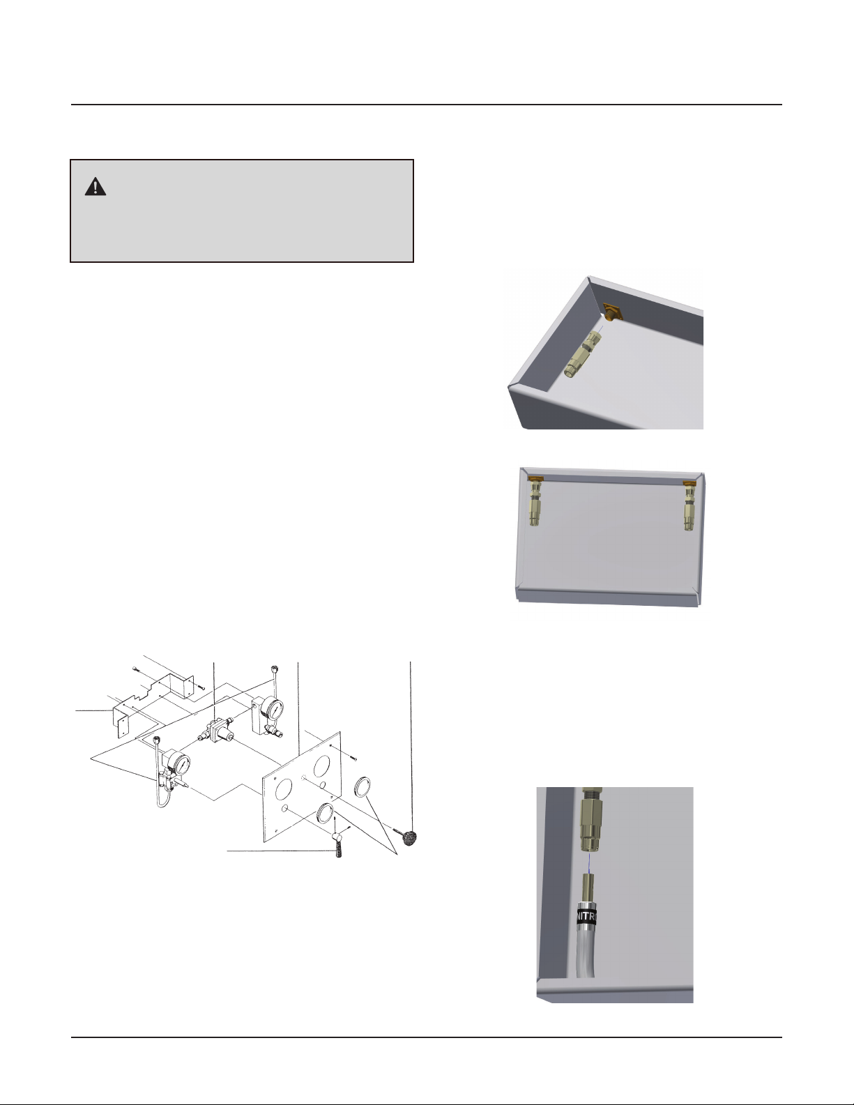
2. Removal of Old Panel
2.1 Remove Ohmeda Front Panel
1. Prior to removal and installation of control
panels, verify zone valve is shut offand line
to control panel is not pressurized.
2. Loosen set screws of on-offvalve handle and
remove handle.
3. Remove regulator adjusting screw and knob
by unscrewing from regulator.
4. Unscrew lens covers from gauges and
remove.
5. Remove screws from cover plate. Remove
cover plate. Discard
6. Disconnect both tubing connections at top of
box.
7. Remove screws in mounting brackets and
remove control panel manifold from box.
Discard.
Figure 1
CAUTION:
Prior to removal and installation of control
panels, verify zone valve is shut offand line to
control panel is not pressurized.
Cover Plate
Regulator
Adjusting Screw
and Knob
Tubing
Connections
On-Off Valve Handle
Gauge Lens
Covers
Regulator
Mounting
Bracket
3. Installing New Panel
3.1 Installing Retrofit Kit
1. Remove flare nut assembly (supplied with
retrofit kit) from polyethylene bag and install
to fittings at top of rough-in box.
2. Remove protective dust caps from hose
ends. Insert hose assembly end into left inlet
connector inside mounting box. Push hose
adapter through collet into connector until it
bottoms out. Pull back on the hose assembly
to verify proper attachment.
Figure 2
Figure 3
Figure 4
Wall Mount Gas Control Panel
4107 9027 47.00 2
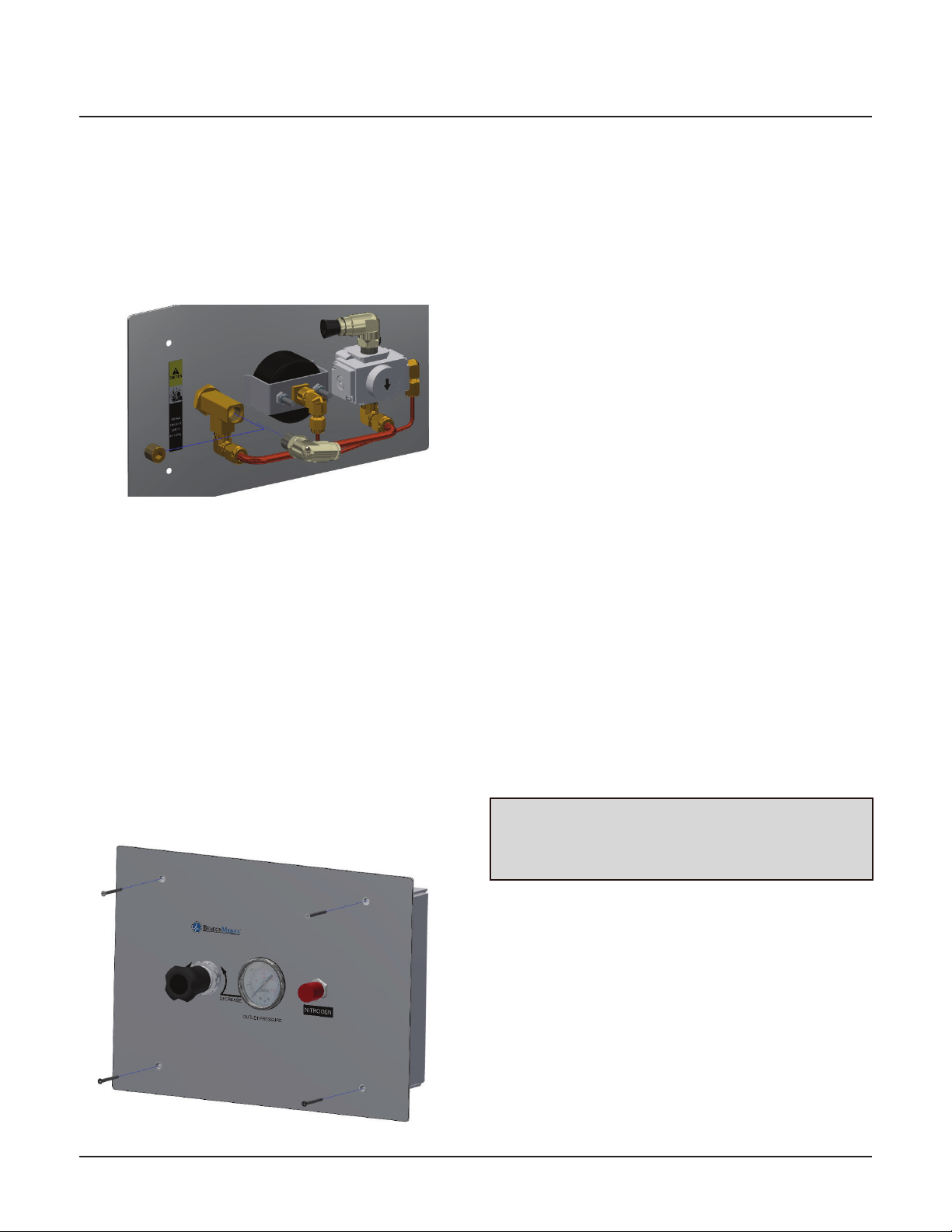
3. Using the same installation procedure from
step 2, connect other hose end to front
panel’s inlet connector.
4. If remote outlet is used, remove pipe plug
from outlet tee fitting and install provided
1/4” MNPT x 3/8” OD tube swivel elbow into
outlet tee fitting.
Figure 6
4. Testing
4.1 Testing Instructions
1. Open the zone valve that supplies gas to the
control panel.
1. Turn pressure adjustment knob clockwise
until reading of 160 psig is shown on the
outlet pressure gage. Pressure will increase
correspondingly with adjustment.
2. Listen at panel for sound of escaping gas
which would indicate leaks.
3. Turn pressure adjustment knob completely
counterclockwise until off. Gas venting
inside the panel shall be heard. Gas is being
vented through the self-relieving pressure
control regulator. Observe outlet pressure
gage, it shall drop to zero and flow of gas
shall terminate.
4.2 Operating Instructions
1. Connect surgical tool supply hose to outlet
connection on control panel or remote outlet
served by control panel.
2. Adjust surgical tool operating pressure
turning pressure adjustment knob clockwise
to increase or counterclockwise to decrease
pressure, as indicated on outlet pressure
gage. For proper operating pressure, consult
tool manufacturer’s recommendations.
NOTE:
It is best to adjust pressure while gas is flowing
through tool.
5. When remote outlet is used, insert hose
assembly end into right remote outlet
connector inside mounting box. Push hose
adapter through collet into connector until
it bottoms out. Pull back on hose assembly
to verify proper attachment. Using same
installation procedure connect other hose
end to front panel’s remote outlet connector.
6. Using leak detection solution, leak test
threaded connection of flare nut and fitting
in rough-in box.
7. Position front panel over rough-in box and
screw into place using (4) #6-32 x 1-1/2”
screws provided with retrofit kit.
Figure 5
Wall Mount Gas Control Panels
4107 9027 47.003

5. Maintenance
CAUTION:
If leaks are heard inside panel, locate zone
valve for room and turn it off. Release
pressure from system before removing
mounting screws.
5.1 Maintenance Instructions
Leak testing internal parts of panel shall be
made without disconnecting panel from piping
system.
1. Remove front panel from wall mounting box
by removing four mounting screws located
on front panel.
2. Carefully pull front panel, with control
assembly, out of mounting box. Support
control assembly in position which allows full
view of all connections.
3. Adjust control pressure to 160 psig. Leak
test all connection using oxygen compatible
leak detection solution. Look for bubbles
indicating leaks. Wipe remaining leak
detection solution from all connections after
testing.
4. Place control panel in mounting box and
secure in place with four mounting screws.
5. Perform test according to section 4.1.
NOTE:
Correct leaks using appropriate procedures.
Wall Mount Gas Control Panel
4107 9027 47.00 4

5 4107 9027 47.00
Wall Mount Gas Control Panels
Notes:

1059 Paragon Way Rock Hill, SC 29730
(888) 4-MEDGAS (888) 463-3427
Fax (803) 817-5750
www.beaconmedaes.com
Table of contents
Popular Control Panel manuals by other brands

GESTRA
GESTRA SPECTORcontrol user manual

B&R
B&R 4PP065.0571-B00 Technical documentation

Cooper Menvier
Cooper Menvier Scantronic 9751 Installation and programming guide

Intermatic
Intermatic T30000R SERIES Installation, operation & service manual

Bticino
Bticino HC 4673 user guide

Honeywell
Honeywell LYNX Touch 5100 Frequently asked questions


