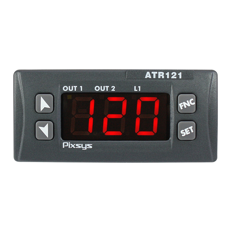
BEAK SD Series User manual

BEAK
BEYOND THE PEAK SD Series User Manual
Brushless Motor Controller
◇Thank you for purchasing BEAK series products.
●“SD series” is the new brushless motor controller series of BEAK.
●It can furthest meet various functions required for controlling the motor.
●It realizes the unprecedented small size, high speed, high efficiency and multifunction.
●The controller is equipped with a display device. The knob is only turned to simply control the speed while
confirming the rotation speed.
◇The User Manual explains the use method and precautions of the product.
●Please read carefully the User Manual before using the product and pay attention to safety when using the
product.
●After reading the User Manual, please keep it in the appropriate place so as to view it at any time.
◇The users of the product shall have the corresponding technology or knowledge.
●Before use, please read carefully “1 precautions” so as to correctly use the product.
●The product belongs to the accessories of industrial automation equipment. Please do not use it in the
medical field or other life-related fields without the permission of the Company.
●It is hereby declared that the Company will not assume any liability to pay compensation on the damage
caused by ignoring this warning. Thanks for understanding.

Table of Contents
1 Safety precautions……………………………………………………………………………………1
1.1 Warning………………………………………………………………………………….………………………..1
1.2 Notice…………………………………………………………………………………………………………...…2
2 Notice for use…………………………………………………………………………………….……3
2.1 Operating environment……………………………………………………………………………….……….…3
2.2 Use limitation. …………………………………….……………………………………………………..……….3
2.3 Machinery maintenance. ……………………………………………………………………………………..…3
3 Product series……………………………………………………….…………………………………4
3.1 Naming rules………………………………………………………………………………………………………4
◇Driving controller naming rules……………………………………………………………………………………4
◇Brushless motor naming rules. …………………………………………………………………………………...4
◇Brushless speed reducing motor naming rules……………………………….…………………….…………..4
3.2 Motor parameters…………………………………………………………………………………………………5
3.3 Driving controller dimension parameters……………………………………………………………….……..11
3.4 Brushless motor controller series……………………………...…………………………………….…….…..12
4 Motor running………………………………………………………………………………………….13
4.1 Connecting line………………………………………………………………………………………………..….13
4.2 Power-on………………………………………………...……………………………………………….……….13
4.3 Running………………………………………………………………………….…………………….………….14
5 Port and wiring…………………………………………………………….…………………….…….15
5.1 Connection of power supply………………………………..…………………………………………………..15
5.2 Input/output signal connection………………………………………………………………………………….15
5.3 Wiring diagram………………………………………………………………...………………………..……….16
6 Function introduction…………………………………………………..……………………………..18
6.1 Function list………………………………………………………………………………………………..……..18
6.2 Driving controller setting………………………………………………...…………………….………………..19
6.3 Parameters list…………………………………………….…………………………………..…………………21
6.4 Contents displayed by the driver…………………………………………………………..…………………..23
6.5 Setting of acceleration and deceleration time………………………………………………………………...24
6.6 Running of externally-inputted signals…………………………………………………………………….…..24
6.7 Two-stage speed running method……………………………………………………………………...……...27
6.8 Setting range of rotation speed limitation………………………………..………………….………………...28
7 Fault alarm instructions………………………………..……………………………………………..29
7.1 Alarm code description………………………………….…………………………………….………………...29
7.3 Fault diagnosis and handling……………………………………………………………………………………31

SD User Manual BEAK
BEYOND THE PEAK
1
1 Safety precautions
In order to make you safely and correctly use the product and nip it in the bud to avoid harm and damage to
you and others, please use the product after fully understanding its contents. Meanwhile, please do not use
the product in the medical field or other life-related special fields without the permission of the Company.
1.1 Warning
The following operations may cause an electric shock. Please do not carry out the following
operations.
●Carry out the movement, wiring and maintenance operations in a power-on state.
●During installation of the product, the protective grounding terminals of the motor and controller are not
grounded.
●During maintenance and inspection, the power supply is not cut off.
The following operations may cause a fire or electric shock. Please do not carry out the following
operations.
●Touch the marked high voltage terminal on the motor controller in a power-on state.
●Fail to correctly carry out the wiring according to the wiring diagram.
●Forcedly bend, pull or clamp the cable.
●Process and remould the motor cable and connecting cable.
●The power supply input voltage of the controller is not controlled within the rated range.
The following operations may cause a fire, electric shock or injury. Please do not carry out the
following operations.
●Use the product in the explosive environment, inflammable gas environment, corrosive environment and
place easy to touch water and near inflammable matters.
The following operations may cause an injury or damage to equipment. Please do not carry out the
following operations.
●Use the product on the vertical device. Once the protective function of the controller works, the motor will
stop so as to cause the falling of the load equipment.
The following operations may cause an electric shock, injury or damage to equipment. Please do not
carry out the following operations.
●Dismantle or modify the motor (speed reducer) and controller. If the interior needs to be checked or
repaired, please contact the original factory of BEAK.
◆Warning and Notice Marks
The controller is marked with the warning and notice labels during use. During the use of the controller,
please be sure to comply with the contents shown in the warning and notice labels.

SD User Manual BEAK
BEYOND THE PEAK
2
1.2 Notice
The following operations may cause an injury or damage to the motor controller and motor.
●Touch the rotating part (output shaft) during running.
●Use hands to touch the motor output shaft (spline, gear cutting part)
●Hold the motor (speed reducer) output shaft and cables in hands during carrying.
●Fail to firmly install the load on the motor (speed reducer) output shaft.
●Fail to install the outer housing on the rotating part (output shaft) of the motor (speed reducer).
●During the assembly of the motor (gear shaft) and speed reducer, place fingers, etc. between the motor
and speed reducer.
●Fail to install the emergency stop button or emergency protection circuit outside the equipment. When the
equipment fault or abnormal action occurs, it cannot be ensured that the whole equipment is in a safe state.
The following operations may cause scalds.
●Touch the motor (speed reducer) and controller within a short time after running or stopping.
The following operations may cause an electric shock.
●Fail to use the insulation screw driver to adjust the acceleration and deceleration time setter of the
controller.
●Fail to use the primary and secondary insulation DC power supply for the input/output signal power supply.
The following operations may cause an injury or damage to equipment.
●Stack the ventilation-obstructing obstacles around the motor and controller.
●Fail to firmly fix the motor (speed reducer) and controller on the installation plate so as to cause falling.
The following operations may cause a fire, electric shock or injury.
●Insert other objects into the opening of the controller.
●Fail to stop running and cut off the controller power supply when abnormity occurs.
●During the use of the motor (speed reducer) and controller, their rated values are exceeded.
◆Even though the motor is in a normal running state, its surface temperature will also exceed 70°C
sometimes.
People may be close to the motor in service. Please post the warning sign shown in the picture on the right
at a prominent position so as to ensure the personal safety. Warning signs

SD User Manual BEAK
BEYOND THE PEAK
3
2 Notice for use
2.1 Operating environment
◇No direct sunlight
◇Less salt
◇Elevation: altitude of less than 1000 m
◇Less dust, iron powder, etc
◇Operating environment humidity: less than 85%
◇No continuous vibration or excessive shock
◇Operating environment temperature: 0 to + 40 ℃
◇Less electromagnetic interference (such as
welding machine, etc.)
◇No explosive environment, harmful gases
(hydrogen sulfide gas, etc.) and liquid
◇No magnetic and radioactive materials or
magnetic field, etc., anti-vacuum environment
2.2 Use limitation.
◇Please do not use it in the vertical load situation.
In the situation of similar vertical load running, the motor speed cannot be controlled. In addition, during
the vertical load running, the variable frequency voltage of the controller will exceed the permissible
value and the protection function will work so that the motor stops, which may cause the load falling and
cause the personal injury or equipment damage.
◇Please do not use the relay to control the power supply.
Please do not use the relay to control the connection and disconnection of the power supply. Using the
relay to connect or disconnect the power supply may cause damage to the motor and controller.
2.3 Machinery maintenance
◇Lubricating oil leakage
When a small amount of lubricating oil leaks from the speed reducer, please install the oil-receiving tray
and other devices to avoid damage to the equipment. Please check whether the leakage of lubricating oil
occurs during regular inspection. Otherwise, the customer’s equipment and products may malfunction
due to oil leakage.
◇Precautions during use in a low temperature environment
When the environment temperature is lower, the oil seal used for the speed reducer and the lubricating
oil viscosity will increase the load torque and reduce the output torque so that the overload fault may
occur. After running for some time, the oil seal and lubricating oil will adapt to the current environment
and the overload fault will not occur so as to make the motor run.
◇Leakage current
There are stray capacitances between the controller power supply line and other power lines and the
ground and motor. These stray capacitances will produce high frequency leakage current so as to cause
adverse effects on surrounding machines. Please use the anti-high-frequency residual-current circuit
breaker for the connecting line between the controller and motor and the ground.
◇Anti-interference
The shielded cable shall be used as the input/output signal cable. If the unshielded cable is used, the
ferrite core can be installed to improve effects.
◇Electrostatic protection
The controller is provided with the semiconductor element, and therefore the electrostatic protection shall
be made in operation. Static electricity, etc. may cause damage to the controller.
◇Connecting line between the motor and controller
Please use the cable connecting line (accessory or optional part) to extend the distance between the
motor and controller.

SD User Manual BEAK
BEYOND THE PEAK
4
3 Product series
3.1 Naming rules
◇Driving controller naming rules
◇Brushless motor naming rules
◇Reduction gearbox naming rules
Series name
SA:SA series
SD:SD series
SH:SH series
SK:SK series
Type
Controller
Power (W)
30:30W、
60:60W、
90:90W、
120:120W
Power supply
voltage
M:AC110
H:AC220
L:DC24
N:DC48
Communication
R: RS-485
No: no RS-485
Rotation speed
display
D: with display
No: no display
Series name
SA:SA series
SD:SD series
SH:SH series
SK:SK series
Type
Motor
Power (W)
30:30W、
60:60W、
90:90W、
120:120W
Power supply
voltage
M:AC110
H:AC220
L:DC24
N:DC48
Rotation speed
1:1000RPM
2:2000RPM
3:3000RPM
Flange
2:60MM
4:80MM
5:90MM
Output shaft number
A:8
B:10
C:12
No: speed reducing
motor
Flange
2:60MM
4:80MM
5:90MM
Speed reducing
ratio
G5:1:5
G10:1:10
G20:1:20

SD User Manual BEAK
BEYOND THE PEAK
5
3.2 Motor parameters
◇60 brushless motor
Specifications
Model
SD-M30H32A
SD-M30L32A
Rated rotation speed (RPM)
3000
Maximum rotation speed (RPM)
3500
Flange dimensions (MM)
60×60
Machine body length (MM)
46.5
Rated power (W)
30
30
Input voltage (V)
AC220
DC24
Number of phases (P)
3
Rated torque (NM)
0.1
0.1
Maximum torque (NM)
0.2
0.2
Rated current (A)
0.175
1.6
Maximum current (A)
0.35
3.2
Allowable voltage fluctuation range
±10%
Protection grade
IP40
Operating temperature
0 ~+40°C
Storage temperature
-25 ~+75°C
Operating humidity
85% RH or below (no condensation)
External dimension drawing

SD User Manual BEAK
BEYOND THE PEAK
6
◇80 Brushless motor
Specifications
Model
SD-M60H34A
SD-M60L34A
Rated rotation speed (RPM)
3000
Maximum rotation speed (RPM)
3500
Flange dimensions (MM)
60×60
Machine body length (MM)
47.5
Rated power (W)
60
60
Input voltage (V)
AC220
DC24
Number of phases (P)
3
Rated torque (NM)
0.2
0.2
Maximum torque (NM)
0.4
0.4
Rated current (A)
0.35
3.2
Maximum current (A)
0.7
6.4
Allowable voltage fluctuation range
±10%
Protection grade
IP40
Operating temperature
0 ~+40°C
Storage temperature
-25 ~+75°C
Operating humidity
85% RH or below (no condensation)
External dimension drawing

SD User Manual BEAK
BEYOND THE PEAK
7
◇90 brushless motor
Specifications
Model
SD-M60H35B
SD-M60L35B
SD-M90H35B
SD-M90L35B
SD-M120H35B
SD-M120L35B
Rated
rotation
speed (RPM)
3000
Maximum
rotation
speed (RPM)
3500
Flange
dimensions
(MM)
90×90
Machine
body length
(MM)
58.8
Rated power
(W)
60
90
120
Input voltage
(V)
AC220
DC24
AC220
DC24
AC220
DC24
Number of
phases (P)
3
Rated torque
(NM)
0.2
0.2
0.3
0.3
0.4
0.4
Maximum
torque (NM)
0.4
0.4
0.6
0.6
0.8
0.8
Rated current
(A)
0.34
3.2
0.53
4.8
0.68
6.25
Maximum
current (A)
0.68
6.4
1.06
9.6
1.36
12.5
Allowable
voltage
fluctuation
range
±10%
Protection
grade
IP40
Operating
temperature
0 ~+40°C
Storage
temperature
-25 ~+75°C
Operating
humidity
85% RH or below (no condensation)
External dimension drawing

SD User Manual BEAK
BEYOND THE PEAK
8
◇60 brushless gear speed reducing motor
Specifications
Model
Motor: SD-M30H32
Reduction gearbox: 2-G □
Motor: SD-M30L32
Reduction gearbox: 2-G □
Rated rotation speed (RPM)
3000
Maximum rotation speed (RPM)
3500
Flange dimensions (MM)
60×60
Machine body length (MM)
46.5
Rated power (W)
30
30
Input voltage (V)
AC220
DC24
Number of phases (P)
3
Rated torque (NM)
0.1
0.1
Maximum torque (NM)
0.2
0.2
Rated current (A)
0.175
1.6
Maximum current (A)
0.35
3.2
Allowable voltage fluctuation
range
±10%
Protection grade
IP40
Operating temperature
0 ~+40°C
Storage temperature
-25 ~+75°C
External dimension drawing

SD User Manual BEAK
BEYOND THE PEAK
9
◇80 brushless gear speed reducing motor
Specifications
Model
Motor: SD-M60H34
Reduction gearbox: 4-G
□
Motor: SD-M60L34
Reduction gearbox: 4-G □
Rated rotation speed (RPM)
3000
Maximum rotation speed (RPM)
3500
Flange dimensions (MM)
60×60
Machine body length (MM)
47.5
Rated power (W)
60
60
Input voltage (V)
AC220
DC24
Number of phases (P)
3
Rated torque (NM)
0.2
0.2
Maximum torque (NM)
0.4
0.4
Rated current (A)
0.35
3.2
Maximum current (A)
0.7
6.4
Allowable voltage fluctuation range
±10%
Protection grade
IP40
Operating temperature
0 ~+40°C
Storage temperature
-25 ~+75°C
External dimension drawing
Key:

SD User Manual BEAK
BEYOND THE PEAK
10
◇90 brushless gear speed reducing motor
Specifications
Model
Motor:
SD-M60H35
Reduction
gearbox: 5-G
□
Motor:
SD-M60L35
Reduction
gearbox: 5-G
□
Motor:
SD-M90H35
Reduction
gearbox:
5-G □
Motor:
SD-M90L35
Reduction
gearbox:
5-G □
Motor:
SD-M120H35
Reduction
gearbox: 5-G
□
Motor:
SD-M120L35
Reduction
gearbox: 5-G
□
Rated rotation
speed (RPM)
3000
Maximum
rotation speed
(RPM)
3500
Flange
dimensions
(MM)
90×90
Machine body
length (MM)
58.8
Rated power
(W)
60
90
120
Input voltage
(V)
AC220
DC24
AC220
DC24
AC220
DC24
Number of
phases (P)
3
Rated torque
(NM)
0.2
0.2
0.3
0.3
0.4
0.4
Maximum
torque (NM)
0.4
0.4
0.6
0.6
0.8
0.8
Rated current
(A)
0.34
3.2
0.53
4.8
0.68
6.25
Maximum
current (A)
0.68
6.4
1.06
9.6
1.36
12.5
Allowable
voltage
fluctuation
range
±10%
Protection
grade
IP40
Operating
temperature
0 ~+40°C
Storage
temperature
-25 ~+75°C
External dimension drawing
Key:

SD User Manual BEAK
BEYOND THE PEAK
11
Torque curve graph
30 W 60W
3.3 Driving controller dimension parameters
Torque [N·m]
Instantaneous
operation area
Continuous
operation area
Rotation speed [r/min]
Torque [N·m]
Instantaneous
operation area
Continuous
operation area
Rotation speed [r/min]
Torque [N·m]
Instantaneous
operation area
Continuous
operation area
Rotation speed [r/min]
Torque [N·m]
Instantaneous
operation area
Continuous
operation area
Rotation speed [r/min]
90W
120W

SD User Manual BEAK
BEYOND THE PEAK
12
3.4 Brushless motor controller series
For this series of controller products, the parameter functions of each model are different. During model
selection, please pay attention to the selection of parameters and functions. The User Manual is a series of
specification documents and does not explain each model. During model selection, please pay attention to
the difference of parameters, functions and specific use methods.
◇AC220V power supply input series (purchase guide)
Model
Input
voltage
Outpu
t
power
RS-48
5
Displa
y
Matched optical axis motor
Matched speed reducing
motor
SD-D30H-RD
AC220
V
30W
■
■
SD-M30H32A
SD-M30H32
SD-D60H-RD
60W
■
■
SD-M60H34A/SD-M60H35
B
SD-M60H34/SD-M60H3
5
SD-D90H-RD
90W
■
■
SD-M90H35B
SD-M90H35
SD-D120H-R
D
120W
■
■
SD-M120H35B
SD-M120H35
SD-D30H-D
30W
■
SD-M30H32A
SD-M30H32
SD-D60H-D
60W
■
SD-M60H34A/SD-M60H35
B
SD-M60H34/SD-M60H3
5
SD-D90H-D
90W
■
SD-M90H35B
SD-M90H35
SD-D120H-D
120W
■
SD-M120H35B
SD-M120H35
SD-D30H
30W
SD-M30H32A
SD-M30H32
SD-D60H
60W
SD-M60H34A/SD-M60H35
B
SD-M60H34/SD-M60H3
5
SD-D90H
90W
SD-M90H35B
SD-M90H35
SD-D120H
120W
SD-M120H35B
SD-M120H35
◇DC24V power supply input series (purchase guide)
Model
Input
voltag
e
Outpu
t
power
RS-48
5
Displa
y
Matched optical axis motor
Matched speed reducing
motor
SD-D30L-RD
DC24
V
30W
■
■
SD-M30L32A
SD-M30L32
SD-D60L-RD
60W
■
■
SD-M60L34A/SD-M60L35
B
SD-M60L34/SD-M60L3
5
SD-D90L-RD
90W
■
■
SD-M90L35B
SD-M90L35
SD-D120L-R
D
120W
■
■
SD-M120L35B
SD-M120L35
SD-D30L-D
30W
■
SD-M30L32A
SD-M30L32
SD-D60L-D
60W
■
SD-M60L34A/SD-M60L35
B
SD-M60L34/SD-M60L3
5
SD-D90L-D
90W
■
SD-M90L35B
SD-M90L35
SD-D120L-D
120W
■
SD-M120L35B
SD-M120L35
SD-D30L
30W
SD-M30L32A
SD-M30L32
SD-D60L
60W
SD-M60L34A/SD-M60L35
B
SD-M60L34/SD-M60L3
5
SD-D90L
90W
SD-M90L35B
SD-M90L35
SD-D120L
120W
SD-M120L35B
SD-M120L35

SD User Manual BEAK
BEYOND THE PEAK
13
4 Motor running
According to the ex-factory setting state, simply explain the running method.
4.1 Connecting line
CN2 connection method
Orange
◆Importance
When powering on again or unplugging and inserting
the connector, please make an interval of at least one
minute after power failure.
Please firmly insert the connector. If the connection of
the connector is not firm, it will result in the abnormal
action of the motor or cause product damage.
4.2 Power-on
According to the diagram above, power on after connection.
Importance
During power-on, if the running switch is moved to RUN and the Alarm code ( ) is
displayed, the motor cannot run. (Alarm is prohibited during running after power-on).
Please move the running switch from RUN to STAND-BY and then move the running switch to
RUN again for normal start.
Please refer to P.20 for the running parameter setting of power-on initial running prohibition fault (Alarm code:
).
Connected to
the power
supply CN2
Use a slot type
screwdriver to press and
hold the orange button so
as to insert the lead wire.

SD User Manual BEAK
BEYOND THE PEAK
14
4.3 Running
Driving controller panel
Driving controller backside
Start
Move the running switch to RUN, and turn the knob rightwards so that the motor starts rotating.
Speed regulation
Slowly turn the knob rightwards to gradually increase the speed, and turn it leftwards to gradually reduce the
speed.
Rapidly turn the knob to quicken the speed change.
Stop
Move the running switch to STAND-BY so that the motor slows down and stops.
Move the running switch to RUN again so that the motor starts rotating according to the set rotation speed.
Rotation direction
Please change the rotation direction through the switch. The change can also be made during running
(ex-factory setting: clockwise rotation)
Specific operations: move the switch to REV so that the motor rotates in the clockwise direction. Move the
switch to FWD so that the motor rotates in the counterclockwise direction.
Display monitoring contents and ALARM
MOOD mode button
Running switch
The motor will run after it is
moved to RUN.
The motor will stop after it
is moved to STAND-BY
SET confirmation button
Speed regulation knob for
regulating the motor speed
Direction toggle switch
RS-485
Communication port (CN4)
Acceleration time knob
Deceleration time knob
Input/output signal
connection (CN3)
Motor connecting
line (CN1)
Power supply input
terminal (CN2)

SD User Manual BEAK
BEYOND THE PEAK
15
5 Port and wiring
5.1 Connection of power supply
Connect the power supply cable to CN2
Input voltage
Connection mode
Low voltage DC input DC24V
Power supply DC+ is connected with the positive terminal
of power supply input, and power supply DC- is connected
with the negative terminal of power supply.
High voltage single phase
100-120V
Power supply LIVE (phase line) is connected with L
terminal, and power supply NEUTRAL (neutral line) is
connected with N terminal.
High voltage single phase
200-240V
Power supply LIVE (phase line) is connected with L
terminal, and power supply NEUTRAL (neutral line) is
connected with N terminal.
●Low voltage 14-32V ●Single phase 100-120V ●Single phase 200-240V
5.2 Input/output signal connection
◇CN3 port introduction
No.
Terminal name
Signal name
Instructions
11
COM0
COM0
Control power supply +5V
10
XO
FWD*
Motor rotation in FWD direction
9
X1
REV*
Motor rotation in REV direction
8
X2
M0*
Multistage speed setting
7
X3
M1*
Multistage speed setting
6
COM1
COM1
Control power supply 0V
5
PWM
PWM
PWM/ frequency speed regulation input
4
ALM+
ALM+
It is ON during ALM, and it is OFF during normal
operation.
3
ALM-
ALM-
2
SPD+
SPD+
The number of pulses outputted after the motor
shaft rotates by a circle.
Refer to the number of magnetic poles for the
number of pulses.
1
SPD-
SPD-
Note: * is the ex-factory setting. The function change can be made through parameters. Please refer to P.21 for
details.
◇Input signal circuit
The input signal is the built-in optical coupling isolation input.
Carry out the control through the internal power supply (+ 5V).
When the external power supply is used, it can be corresponding to NPN control input and PNP control input
through the change of the wiring mode.
Connectable external power supply: DC24V -15% to + 20%, more than 100 mA.

SD User Manual BEAK
BEYOND THE PEAK
16
5.3 Wiring diagram
◇NPN logical control
Wiring when using the transistor output-type upper controller to control the motor.
◇Switch type wiring
Wiring when using the switch, relay and other contact switches to control the motor.
Driver
Power supply connection
Motor connecting device
Motor connection
Motor
Speed regulation input
PWM
Output signal connection
DC4.5-30.0V
More than 100mA
R Recommended resistance value
For DC24V 510Ω-2.4KΩ(2W)
For DC5V 100Ω-510Ω(0.5W)
Power supply connection
Driver
Motor connecting device
Motor connection
Motor
Speed regulation input
PWM
Output signal connection
DC4.5-30.0V
More than 100mA
R Recommended resistance value
For DC24V 510Ω-2.4KΩ(2W)
For DC5V 100Ω-510Ω(0.5W)

SD User Manual BEAK
BEYOND THE PEAK
17
◇PNP logical control
Wiring when using the transistor output-type upper controller to control the motor
◇Output port wiring diagram
PLC detection output signal wiring
Output control relay
Power supply connection
Driver
Motor
Motor connecting device
Motor connection
Input signal connection
DC20.4-28.8V
More than 100mA
Speed regulation input PWM
Output signal connection
DC4.5-30.0V
More than 100mA
R Recommended resistance value
For DC24V 510Ω-2.4KΩ(2W)
For DC5V 100Ω-510Ω(0.5W)
Driving controller
Driving controller
Relay
Power supply

SD User Manual BEAK
BEYOND THE PEAK
18
6 Function introduction
6.1 Function list
Function
Contents
Operation
mode
Reference
source
Display
1: Rotation speed display
Monitoring
2: Current display
3: Voltage display
4: Temperature display
5: ALARM code display
6: Speed of speed reducer output shaft
after the setting of conversion
Rotation speed setting
1: Set the motor speed through the knob
Parameters
2: Set the motor speed through figures
3: Set the motor speed through the
external signal input
Setting of acceleration and
deceleration time
1: Set the acceleration and deceleration
time of the motor through the knob
2: Set the acceleration and deceleration
time of the motor through figures
Operation carried out
through external signals
Control the operation through external
signals
Rotation speed setting
range limitation
Set the upper and lower limits of rotation
speed
Keep it simple
Keep the load during stopping
485 control
Carry out the address selection and
control
Gear ratio setting
Set the speed ratio of the adaptive speed
reducer
Magnetic polarity setting
Set different magnetic poles.
Overload time setting
Set the time from overload to output
Multistage speed data
setting
Set the multistage speed data
Data initialization
Restore the operating data to the factory
default setting
Note
Some models of BEAK products have no display and setting function or no RS-485 function. Please
pay attention to the required function during model selection so as to avoid the wrong model
selection.
This manual suits for next models
2
Table of contents
