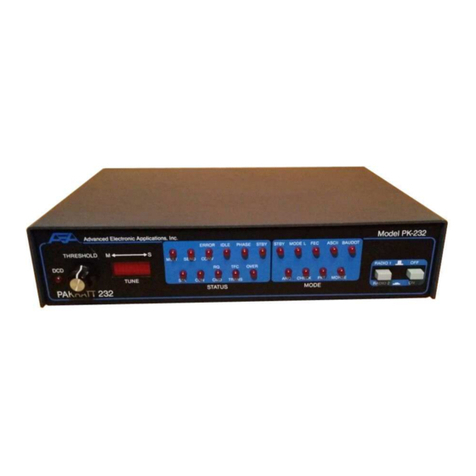
AEA PAKRATT PK-232 Product manual

TECHNICAL REFERENCE MANUAL
MODEL PK-232 DATA CONTROLLER
ADVANCED ELECTRONICS APPLICATIONS, INC.
(Preliminary Release)

PK-232 TECHNICAL MANUAL
PK232TM Rev. A 5/87 i Page 2
PREFACE TO THE PK-232 TECHNICAL REFERENCE MANUAL
Please ead this p eface in its enti ety. It contains info mation about how to eceive wa anty se v-
ice f om AEA, the cu ent softwa e installed in you PK-232 and AEA's softwa e update policy. This
info mation is impo tant; if you do not ead it, you may damage you unit.
RF Inte fe ence Info mation To Use
This PK-232 has been ce tified unde the limits fo Class B computing devices unde Subpa t J of
Pa t 15 of the FCC ules, and is listed unde FCC Identification Numbe DLX42690056.
This equipment gene ates and uses adio f equency ene gy. If it is not installed and used p ope ly,
that is, in st ict acco dance with AEA's inst uctions, it may cause inte fe ence to adio and TV e-
ception. It has been type tested and has been found to comply with the limits of a Class B comput-
ing device in acco dance with the specifications in Subpa t J of Pa t 15 of the FCC ules, which a e
designed to p ovide easonable p otection against such inte fe ence in a esidential installation.
Howeve , the e is no gua antee that inte fe ence will not occu in a pa ticula installation. If this
equipment does cause inte fe ence to adio o TV eception, which can be dete mined by tu ning
the PK-232 on and off, the use is encou aged to t y and co ect the inte fe ence using one o
mo e of the following measu es:
Reo ient the antenna of the device eceiving inte fe ence.
Relocate the compute with espect to this device.
Plug the compute into diffe ent outlet so the compute and the device a e on diffe ent b anch
ci cuits.
If necessa y, the use should consult the deale o an expe ienced Radio/TV technician fo additio-
nal suggestions. The use may find 'How to Identify and Resolve Radio-TV Inte fe ence P oblems',
a booklet p epa ed by the FCC, helpful.
USE SHIELDED CABLE FOR ALL RS-232 CONNECTIONS
As pa t of its continuing p og am of p oduct imp ovement, AEA ese ves the ight to make changes
in this p oduct's specifications. Changes will be made pe iodically to the info mation in this docu-
ment. These changes will be inco po ated in new issues of this manual.
The e may be technical in accu acies o typog aphical e o s in this document. Please add ess
comments and co ections to AEA Inco po ated, PO Box C2160, Lynnwood, WA 98036-0918. AEA
ese ves the ight to inco po ate and issue any info mation thus supplied in whateve manne it
deems suitable without incu ing and obligations whateve .
FIRST ISSUE - PRELIMINARY RELEASE (MAY 1987)
I/A/W Softwa e Release Date 21-Jan-87

PK-232 TECHNICAL MANUAL
PK232TM Rev. A 5/87 ii Page 3
INTRODUCTION
You AEA PK-232 Data Cont olle is the connection between you compute and adios. The PK-232
pe fo ms all of the cont ol, modulation, demodulation, coding and encoding function equi ed to
establish and maintain data and text communications between you station and any othe suitably-
equipped station, as well as othe communication facilities equipped fo digital communications.
The PK-232's packet system softwa e is de ived f om and compatible with the o iginal TAPR TNCs
and p esents many of the advanced featu es of that design, coupled with significant enhance-
ments based on expe ience gained by thousands of TAPR-equipped amateu packet stations wo ld-
wide.
This manual is you efe ence guide to the technical aspects of the PK-232, its maintenance and
epai , as well as special softwa e info mation fo p og amme s and applications develope s in digi-
tal Amateu Radio.
BATTERY BACK-UP
You PK-232 uses batte ies to back up the use -p og ammable values in the system. If you don't
install batte ies, you'll have to e-ente all of you pe sonal system settings each time you tu n on
the PK-232. You PK-232 will ope ate no mally in all modes but will not etain you pe sonalized pa-
amete s such as you call sign, until you install th ee AA-size batte ies in the batte y holde inside
the chassis cove . We ecommend that you choose alkaline batte ies fo this application.
Remove the fou sc ews f om the sides and the two sc ews f om the ea of the chassis. then
lift off the PK-232's cove . Take ca e not to distu b the black o ed wi es that attach the bat-
te y holde to the p inted ci cuit boa d.
Find the positive and negative symbols embossed on the inside of the batte y holde . Inse t
each batte y, ca efully matching the positive symbols on the batte y with the positive symbols
on the holde .
Replace the cove and the six sc ews.
The batte y back-up etains all the pa amete s except the time-of-day clock and the MHEARD
(Monito Hea d) list. These two functions a e cont olled by the mic op ocesso .

PK-232 TECHNICAL MANUAL
PK232TM Rev. A 5/87 TOC-1 Page 4
TABLE OF CONTENTS
CHAPTER 1 – INTRODUCTION
Pa ag aph Page
1.1 Int oduction ..................................................................................... 1-1 7
1.2 Scope .............................................................................................. 1-1 7
1.3 Gene al Desc iption ........................................................................... 1-1 7
1.4 Specifications .................................................................................... 1-1 7
1.4.1 Ope ating Modes .................................................................... 1-2 8
1.4.2 Modem Cha acte istics ............................................................ 1-2 8
1.4.3 P ocesso System ................................................................... 1-2 8
1.4.4 Input/Output Connections ....................................................... 1-2 8
1.4.5 Cont ols and Indicato s ........................................................... 1-3 9
1.4.6 Gene al ................................................................................. 1-3 9
CHAPTER 2 – FUNCTIONAL DESCRIPTION
2.1 Majo Sections .................................................................................. 2-1 10
2.1.1 Analog Section ....................................................................... 2-1 10
2.1.2 Digital Section ........................................................................ 2-1 10
2.1.3 Input/Output Section .............................................................. 2-1 10
2.1.4 Display Section ....................................................................... 2-1 10
2.1.5 Powe Dist ibution .................................................................. 2-1 10
CHAPTER 3 – THEORY OF OPERATION
3.1 System Diag ams .............................................................................. 3-1 11
3.1.1 Block Diag ams ...................................................................... 3-1 11
3.1.2 Logic Diag ams ...................................................................... 3-1 11
3.1.3 Schematic Diag ams ............................................................... 3-1 11
3.2 Analog Subsystem ............................................................................. 3-2 12
3.2.1 Receive Function .................................................................... 3-2 12
3.2.1.1 Receive Ci cuits ........................................................... 3-2 12
3.2.2 T ansmit Function ................................................................... 3-3 13
3.2.2.1 T ansmit Ci cuits .......................................................... 3-3 13
3.3 Digital Subsystem ............................................................................. 3-3 13
3.3.1 Z80A Cent al P ocessing Unit ................................................... 3-3 13
3.3.2 Memo y ................................................................................. 3-4 14
3.3.3 8536 CIO Counte /Time and Pa allel I/O Unit .......................... 3-4 14
3.3.4 8530 SCC Se ial Communications Cont olle .............................. 3-6 16

PK-232 TECHNICAL MANUAL
PK232TM Rev. A 5/87 TOC-2 Page 5
CHAPTER 4 – HOST MODE AND SPECIAL APPLICATIONS
Pa ag aph Page
4.1 Int oduction to Host Mode ................................................................. 4-1 18
4.1.1 Why Do We Need a Host Mode ................................................ 4-1 18
4.1.2 How does Host Mode Help Us? ................................................ 4-1 18
4.1.3 Ente ing Host Mode ................................................................ 4-2 19
4.1.4 Leaving Host Mode ................................................................. 4-2 19
4.1.5 The Host Mode Dialog ............................................................. 4-2 19
4.1.6 Host Mode Recove y ............................................................. 4-3 20
4.2 Host Compute Commands ................................................................ 4-3 20
4.2.1 Unsuppo ted Commands ......................................................... 4-4 21
4.2.2 Host Mode Mnemonic Indicato s .............................................. 4-4 21
4.2.3 CONNECT and DISCONNECT ................................................... 4-5 22
4.2.4 ON/OFF Booleans o Switches ................................................. 4-5 22
4.2.5 TXDELAY ............................................................................... 4-5 22
4.2.6 SENDPAC ............................................................................... 4-5 22
4.2.7 Inte ogation o Que y Commands ........................................... 4-5 22
4.3 PK-232 Responses ............................................................................. 4-5 22
4.3.1 Responses to Inte ogation o Que y Commands ....................... 4-6 23
4.3.2 OPMODE Response ................................................................. 4-7 24
4.3.3 Link Status Request Response ................................................. 4-7 24
4.3.4 Call Sign Fo mats ................................................................... 4-7 24
4.4 Sending Data to the PK-232 ............................................................... 4-8 25
4.4.1 Data Polling ........................................................................... 4-8 25
4.4.2 The HPOLL Command ............................................................. 4-8 25
4.4.3 Special Case in AMTOR ........................................................... 4-9 26
4.4.4 Link Messages ........................................................................ 4-9 26
4.5 Host Mode and Special Packet Applications ......................................... 4-9 26
4.6 Raw HDLC ........................................................................................ 4-9 26
4.7 "KISS" TNC Asynch onous Packet P otocol .......................................... 4-10 27
4.7.1 Sta ting "KISS" TNC Ope ation ................................................ 4-11 28
4.7.2 "KISS" TNC Special Cha acte s ................................................. 4-11 28
4.7.3 "KISS" TNC F ame St uctu e .................................................... 4-11 28
4.7.4 "KISS" TNC Commends ........................................................... 4-11 28
4.7.4.1 TXDELAY: CTL = $01 .................................................... 4-11 28
4.7.4.2 PERSISTENCE: CTL = $02 ............................................ 4-12 29
4.7.4.3 SLOTTIME: CTL = $03 .................................................. 4-12 29
4.7.4.4 TXTAIL: CTL = $04 ...................................................... 4-12 29
4.7.4.5 FULLDUP: CTL = $05 ................................................... 4-13 30
4.7.4.6 HOST OFF: CTL = $FF .................................................. 4-13 30
4.7.4.7 DATA: CTL = $00 ......................................................... 4-13 30
4.8 Maximum Block Size .......................................................................... 4-14 31
4.9 MEMORY, I/O and ADDRESS Commands ............................................. 4-14 31
4.9.1 MEMORY Command ................................................................ 4-14 31
4.9.2 ADDRESS Command ............................................................... 4-14 31
4.9.3 I/O Command ........................................................................ 4-15 32
4.10 Conve se and T anspa ent Modes ....................................................... 4-15 32
4.11 MHEARD Command in Host Mode ....................................................... 4-15 32
4.12 Softwa e Release Date Code .............................................................. 4-16 33
4.13 P oduct Type Code ............................................................................ 4-16 33

PK-232 TECHNICAL MANUAL
PK232TM Rev. A 5/87 TOC-3 Page 6
CHAPTER 5 – MECHANICAL ASSEMBLY AND DIS ASSEMBLY
Pa ag aph Page
5.1 Cove Removal .................................................................................. 5-1 34
5.2 Ci cuit Boa d Removal ....................................................................... 5-
5.3 Ci cuit Boa d Assembly ...................................................................... 5-2 35
5.4 Cove Assembly ................................................................................ 5-
CHAPTER 6 – ADJUSTMENTS
6.1 P elimina y Setup .............................................................................. 6-1 36
6.2 Calib ation P ocedu e ........................................................................ 6-
6.2.1 AFSK Gene ato (T ansmit) Adjustments ................................... 6-2 37
6.2.2 Demodulato (Receive) Adjustments ........................................ 6-3 38
6.3 Functional Tests ................................................................................ 6-
CHAPTER 7 – TROUBLESHOOTING
7.1 Int oduction ..................................................................................... 7-1 40
7.2 Gene al Tests .................................................................................... 7-
7.2.1 Powe Supply ......................................................................... 7-
7.2.2 Obvious P oblems ................................................................... 7-2 41
7.2.3 Assembly P oblems ................................................................. 7-
7.2.4 Cabling P oblems .................................................................... 7-
7.3 Specific Symptoms ............................................................................ 7-
7.3.1 Symptom: Cont olle appea s dead .......................................... 7-
7.3.2 Symptom: Modem cannot be calib ated .................................... 7-4 43
7.3.3 Symptom: T ansmitte cannot be keyed ................................... 7-
7.3.4 Symptom: T ansmitte signals not copyable by othe stations ..... 7-
7.3.5 Symptom: Received signals not copyable .................................. 7-
7.4 Te minal Inte face T oubleshooting ..................................................... 7-5 44
7.4.1 Symptom: Cont olle does not communicate with the te minal .... 7-
7.4.2 Symptom: Cont olle signs on with mutilated data ..................... 7-
7.4.3 Symptom: Cont olle does not espond o accept commands ..... 7-6 45
APPENDIX A – AX.25 LEVEL 2 PROTOCOL ..................................................... A 46
APPENDIX B – "KISS" TNC SPECIFICATION ................................................... B 70
APPENDIX C – DRAWINGS ........................................................................... C 75
APPENDIX D – WAVEFFORMS ....................................................................... D 83
Last Page 101

PK-232 TECHNICAL MANUAL CHAPTER 1 – INTRODUCTION
PK232TM Rev. A 5/87 1-1 Page 7
CHAPTER 1 – INTRODUCTION
1.1 Int oduction
This Technical Refe ence Manual will assist you to maintain, epai and adjust you PK-232
Data Cont olle . Please use this manual in conjunction with AEA's Ope ating Manual fo the
PK-232, Revision D.
The PK-232 Ope ating Manual contains complete and detailed info mation on cont olle op-
e ating p ocedu es, cont olle commands and syntax, gene al installation methods, te minal
and adio connections, as well as connecto wi ing diag ams, p inted ci cuit boa d sche-
matics, boa d layout d awings and pa ts list.
1.2 Scope
This manual includes info mation on theo y of ope ation, ha dwa e desc iptions and t ouble-
shooting inst uctions and cha ts. In addition, detailed info mation on the PK-232's Host
mode is p esented fo the benefit of p og amme s and softwa e application develope s.
1.3 Gene al Desc iption
AEA's Model PK-232 is a multi-mode p otocol conve te and data cont olle that includes
self-contained modems fo all modes.
The PK-232 sends and eceives Mo se Baudot and ASCII RTTY, facsimile, AMTOR/SITOR and
AX.25 packet. The PK-232 conve ts these signals to ASCII data end sends the data to you
te minal via an EIA standa d RS-232 (CCITT V.24/V.28) se ial po t, and to you p inte via a
special Cent onics-type pa allel inte face. Except fo the p inte inte face, the eve se p oce-
du es conve t ASCII data typed at you te minal to the signals and p otocols equi ed fo
t ansmission to othe stations.
All necessa y tone gene ation and demodulation (modem) functions a e built in; howeve ,
exte nal modems can be connected to the PK-232 via dedicated ea -panel connecto s. All
decoding, encoding, p otocol and t ansmitte cont ol outines a e sto ed in the PK-232's
fi mwa e in PROM and inte nal p og am memo y.
Ope ating modes, speeds, modem tone pai s, filte bandwidths and system p otocols a e se-
lected by typing commands on you compute o data te minal. Any communications o te -
minal emulato no mally used with a telephone line modem can be used with the PK-
232.
1.4 Specifications
As pa t of its p og am of p oduct imp ovement, AEA ese ves the ight to make changes in
this p oduct's specifications. Changes will be made to the info mation in this document and
inco po ated in evisions to this manual. Specifications a e subject to change without notice.
1.4.1 Ope ating Modes
The PK-232 p ovides ope ation in Mo se, Baudot, ASCII, AMTOR/SITOR, half- o full-du-
plex Packet Radio in acco dance with AX.25 p otocols, facsimile, SIAM and Host and
"KISS" TNC modes fo use with packet p otocols othe than AX.25.

PK-232 TECHNICAL MANUAL CHAPTER 1 – INTRODUCTION
PK232TM Rev. A 5/87 1-2 Page 8
1.4.2 Modem Cha acte istics
Demodulato : Limite -disc iminato type, p eceded by an eight-pole
Chebyshev 0.5 dB ipple bandpass filte
Receive bandpass: Automatically switched by ope ating mode
VHF packet: Cente f equency 1700 Hz, bandwidth 2600 Hz
HF (except CW): Cente f equency 2210 Hz, bandwidth 450 Hz
CW: Cente f equency 800 Hz, bandwidth 200 Hz
Modulato : Low-disto tion AFSK sine wave function gene ato ,
phase-continuous AFSK
Output Level: 5 to 100 millivolts RMS, adjustable by ea -panel con-
t ol
1.4.3 P ocesso System
P otocol conve sion: Zilog Z-80 mic op ocesso
RAM: 16 kilobytes
ROM: Up to 48 kilobytes of ROM may be used
Ha dwa e HDLC: Zilog 8530 SCC
1.4.4 Input/Output Connections
Radio Inte face: Two five-pin TTL connecto s, selectable on the f ont
panel
Input/output Lines: Receive audio
T ansmit audio
Push-To-Talk (PTT)
Exte nal squelch input
G ound
Exte nal modem connecto Five-pin TTL - TXD, RXD, DCD, PTT, G ound
Di ect FSK Outputs No mal and eve se
Oscilloscope Outputs Ma k (Stop) and Space (Sta t)
CW keying Outputs Positive: +100 VDC max. at up to 100 mA
Negative: -30 VDC max. at up to 20 mA
Te minal Inte face: RS-232C 25-pin DB25 connecto
Input/Output RS-232 with full ha dwa e and softwa e handshake on
wi es 1-8 and 20
Te minal Data Rates Auto-baud selection of 300, 1200, 2400, 4800 and
9600 BPS. TBAUD adds 110, 150, 200 and 600 BPS.

PK-232 TECHNICAL MANUAL CHAPTER 1 – INTRODUCTION
PK232TM Rev. A 5/87 1-3 Page 9
1.4.5 Cont ols and Indicato s
F ont Panel Cont ols: Powe Switch
Radio Selecto Switch
Th eshold Adjust
Indicato s: Ten-segment disc iminato -type ba g aph indicato fo
HF tuning.
DCD LED (Data Ca ie Detect)
Status and Mode Indicato s: Mode G oup Status G oup
BAUDOT STBY
ASCII PHASE
PKT IDLE
MORSE ERROR/CONV
CHECK OVER
FEC TFC/TRANS
ARQ RQ/CMD
MODE L CON
STBY STA
MULT
SEND
1.4.6 Gene al
Powe Requi ements: +13 VDC (12 to 16 VDC) at 700 mA
Mechanical: Ove all 11" × 8.25" × 2.5" (279.4 × 209.6 × 63.5 mm)
Weight 3 pounds (1.36 kilog ams)

PK-232 TECHNICAL MANUAL CHAPTER 2 – FUNCTIONAL DESCRIPTION
PK232TM Rev. A 5/87 2-1 Page 10
CHAPTER 2 – FUNCTIONAL DESCRIPTION
2.1 Majo Sections
The PK-232 Data Cont olle has five majo functional blocks:
o Analog o Display
o Digital o Powe Dist ibution
o Input/Output (I/O)
Each of these functional blocks has its own distinct functions. The following pa ag aphs de-
sc ibe each section.
Refe to the PK-232 Functional Block Diag am, Figu e 1 in Appendix C, while eading these
desc iptions.
2.1.1 Analog Section
The analog section consists of active filte s, limite s, a th eshold detecto , DCD (Data Ca -
ie Detect and diode disc iminato ci cuits. Analog switches automatically adjust va ious
ci cuit cha acte istics fo each ope ating mode.
2.1.2 Digital Section
The digital section contains a mic op ocesso , ead only memo y (ROM) andom access
memo y (RAM), two c ystal-cont olled clock gene ato s an a va iety of "glue" chips to
gate and isolate the digital signals.
2.1.3 Input/Output Section
The I/O Section p ovides a standa d se ial data path in acco dance with EIA RS-232-C
and CCITT Recommendations V.24/V.28, between the PK-232 and the associated com-
pute o te minal.
The I/O section contains an HDLC (High-Level Data Link Cont ol) t anslato ; output d iv-
e s fo AFSK tones, DC logic voltages fo di ect FSK t ansmitte keying, CW DC keying sig-
nals, a watchdog time and PTT (push-to-talk) switching voltages fo the associated t ans-
mitte .
The I/O section also isolates input and output cont ol signal buffe s and p ovides ci cuits
fo connecting an exte nal modem.
All cont ol and communications to and f om the PK-232 pass th ough the I/O section.
2.1.4 Display Section
The display section consists of a tuning indicato and its associated d ive ; status and
mode indicato s with thei d ive s and eceive s; a DCD indicato and a th eshold cont ol.
2.1.5 Powe Dist ibution Section
The Powe dist ibution section contains voltage egulato s, DC-to-DC conve te s fo the
PK-232's ope ating system and a batte y system fo backing up maintaining the data
sto ed in RAM.

PK-232 TECHNICAL MANUAL CHAPTER 3 – THEORY OF OPERATION
PK232TM Rev. A 5/87 3-1 Page 11
CHAPTER 3 – THEORY OF OPERATION
3.1 System Diag ams
Please efe to APPENDIX C fo the va ious diag ams used as efe ence in this chapte .
3.1.1 Block Diag ams
Refe to the Functional Block Diag am, Figu e 1 in APPENDIX C. Dashed lines sepa ate the
five sections of the PK-232. Each section will be desc ibed sepa ately and is labeled as fol-
lows:
o Analog
o Digital
o Input/Output (I/O)
o Display
o Powe Dist ibution
3.1.2 Logic Diag ams
Refe to the Logic Diag am, Figu e 2 in APPENDIX C. Figu e 2 shows the digital logic po -
tion of the PK-232 which includes:
o the mic op ocesso
o Read Only Memo y (ROM)
o Random Access Memo y (RAM)
o clock and cont ol logic
o pa t of the display logic
o the logic associated with the digital communications between the PK-
232 and the te minal.
The majo po tion of the powe dist ibution section is also shown on this d awing.
3.1.3 Schematic Diag ams
Refe to the Schematic Diag am, Figu e 3 in APPENDIX C. Figu e 3 shows the analog po -
tion of the PK-232, which includes:
o mode-dependant bandpass filte s
o MARK and SPACE esonato s
o audio f equency disc iminato
o mode-dependant low pass filte
o compa ato ci cuit y
o AFSK gene ato
o watchdog time
o t ansmitte audio d ive
o keying ci cuit y
o adio switching
o tuning indicato ci cuit y

PK-232 TECHNICAL MANUAL CHAPTER 3 – THEORY OF OPERATION
PK232TM Rev. A 5/87 3-2 Page 12
3.2 Analog Subsystem
Each of the PK-232's ope ating modes equi es diffe ent bandwidths, as well as va ying
AFSK tone and speed cha acte istics. The analog ci cuit y is adapted to these diffe ences by
using p og am-cont olled switches to place p ecision esisto s in pa allel with the fixed com-
ponents of the ci cuits. In this manne , unde softwa e command, the analog ci cuits a e op-
timized fo the mode selected.
3.2.1 Receive Function
Audio signals f om the selected RADIO 1 o RADIO 2 input pass th ough a olloff filte to
compensate fo VHF eceive cha acte istics and a e then applied to a buffe amplifie to
limit audio signal amplitude.
The signal then pass th ough a bandpass filte whose cente f equency tuning and band-
width a e cont olled by the OPMODE selection fo optimum cha acte istics.
The bandwidth-limited signals pass th ough an amplitude limite to emove va iations in
audio levels. Ma k and Space tones a e sepa ated in the Ma k and Space esonato s. The
sepa ated Ma k and Space output signals a e ectified in a diode disc iminato ci cuit.
The detected data is filte ed in an active lowpass filte and compa ed with a efe ence
voltage in a slice ci cuit to digitize the data. The esulting data is then shaped and in-
ve ted fo passing to the inte nal modem ci cuit y.
When a full wo d of data (eight bits) has been assembled in the modem ci cuit y, an inte -
upt is gene ated to the mic op ocesso which then p ocesses the data.
3.2.1.1 Receive Ci cuits
The eceived audio signals a e outed th ough one of two adio connection eceptacles,
J4 (RADIO 1) o J6 (RADIO 2), o th ough the espective pa alleled adio input cable
jacks, J3 o J5. The adio is selected by SW2, the RADIO 1/RADIO 2 push-button switch
on the f ont panel. Radio input and output connections a e bypassed fo RF by C64 and
C63.
The audio input consists of esisto -capacito combination R34 and C54 to compensate
fo the audio cha acte istics of the ave age VHF FM adios by emphasizing highe -f e-
quency tones and attenuating lowe -f equency tones.
Input buffe amplifie U28-D limits eceived audio signal levels to p event ove loading
multiple- esonato feedback-type 0.5-dB- ipple Chebyshev active bandpass filte fo med
by ope ational amplifie s U23 and U26.
Analog gates (FET switches) U22, U24, U25, U26 and U27 select filte cente f equency
and bandwidth. Gate selection is a function of the ope ating mode.
Bandpass-filte ed output signals a e amplified and limited by U28-A to emove ampli-
tude va iations and passed to MARK and SPACE esonato s U30 and U32. Gate U29 de-
te mines the tone-pai esonato tuning.
Fo CW signals, U31 t ansfe s the bandpass filte output di ectly to the MARK channel
disc iminato . The SPACE channel is decoupled f om the ci cuit and igno ed.

PK-232 TECHNICAL MANUAL CHAPTER 3 – THEORY OF OPERATION
PK232TM Rev. A 5/87 3-3 Page 13
The tones p ocessed by the esonato s a e ectified in a full-wave diode netwo k
fo med by D19 and D20 fo the MARK channel, and D22 and D23 fo the SPACE chan-
nel. The MARK signal is positive with espect to the voltage efe ence (VR); the SPACE
signal is negative.
Output signals f om both channels a e envelope-detected simultaneously by a sho t and
long time-constant netwo k and summed at the input of U32-B.
Afte passing th ough a lowpass filte to emove ipple, the signal is amplified by U32-C,
U34-C and U34-D and then squa ed. Its logic level is shifted by a TTL inve te U15-C fo
use by eithe an exte nal modem o U6, a Zilog 8536 Counte /Time and Pa allel I/O
Device.
3.2.2 T ansmit Function
Digital input signals f om the te minal a e eceived by the se ial cont olle and passed to
the mic op ocesso fo action. If ECHO has been commended ON, the input signals a e
outed by the se ial cont olle back to the te minal fo display.
3.2.2.1 T ansmit Ci cuits
Data to be t ansmitted is eceived ove the RS-232 se ial po t and ead by Z8530 Se ial
Communications Cont olle U7 unde the cont ol of the Z80 mic op ocesso . The data is
pe iodically sent ove the data bus to the Z8536, U6. The Z8536 t anslates the data into
a bina y st ing at the co ect data ate and outes the bina y st ing to AFSK gene ato
U40.
The AFSK gene ato supplies one of two tones to selected RADIO connecto J4 o J6,
depending on the position of RADIO 1/Radio 2 switch SW2.
The t ansmit tone pai p oduced by the tone gene ato is selected by FET switch U35.
This switch selects app op iate f equency-dete mining esisto s R164, R165, R157 and
R168, in acco dance with the selected ope ating mode.
In addition, a logic level of five volts DC (5 VDC) o g ound is p esented at Scope/FSK
eceptacle J7, eithe inve ted o no mal, fo FSK t ansmitte keying.
At the same time that the gene ato is keyed, a Push-to-Talk (PTT) signal is supplied to
t ansisto keye s (Q4 and Q5). The pola ity of the keying signal is selected by jumpe s
JP2 and JP3 fo the two adio eceptacles.
This PTT signal is p esent as long as pulses f om the time in U7 ef esh the timeout ci -
cuit y of Q10 and Q3. If fo any eason the p og am fails o becomes disabled, the
timeout ci cuit y p events the PTT line f om being activated.
3.3 Digital Subsystem
In the following discussion of the Digital Subsystem, the dolla sign ($) indicates hexadeci-
mal numbe s.
3.3.1 Z80A Cent al P ocessing Unit
The p ocesso , U1, is a Z80A ope ating at 4.0 MHz. The pe iphe al chips U6 and U7 cause
system inte upts using the CPU's INT* input (pin 16). The NMI* and BUSRQ* inputs a e
unused, as a e the RFSH, HALT and BUSAK outputs.

PK-232 TECHNICAL MANUAL CHAPTER 3 – THEORY OF OPERATION
PK232TM Rev. A 5/87 3-4 Page 14
3.3.2 Memo y
The PK-232 memo y consists of 48 kB of EPROM at U2 and U3, and 16 kB of static RAM
at U4 and U5.
U2 is a 27256 EPROM which occupies the 32 kB add ess space between $0000 and
$7FFF.
EPROM U3 is a 27128 occupying 16 kB f om $8000 to $BFFF.
The ead-w ite memo y consists of two 6264 8 kB volatile static RAMs, U4 occupying
$C000-DFFF and U5 at $E000-FFFF. Both U4 and U5 have thei powe backed up by bat-
te ies when the system powe is off.
The 74LS139 add ess decode at U10 eceives add ess bits A13, A14 and A15 f om the
CPU, and p ovides chip enables fo U3, U4 and U5. Add ess bit A15 is used di ectly as the
chip enable fo the U2 EPROM at add ess $0000.
U17 pin 8 p ovides a Memo y Read (OE*) line fo U2, U3, U4 and U5. U17 pin 11 is the
Memo y W ite (·WE*) line fo the RAMs U4 and U5.
3.3.3 8536 CIO Counte /Time and Pa allel I/O Unit
U6 is an 8536 CIO chip which p ovides 20 pa allel I/O pins and th ee time s. This chip e-
ceives add ess bits A0, A1 and A6 f om the CPU. The PK-232's fi mwa e add esses the
8536 by fo cing all othe add ess bits high, yielding these add esses:
$BC - Pa allel po t A data
$BD - Pa allel po t B data
$BE - Pa allel po t C data
$BF - Cont ol po t
The 8536 uses the CPU's 4.0 MHz clock on the PCLK input (pin 16). The 8536 inte upt
has p io ity ove the inte upt f om the 8530 (U7).
Pa allel po t A cont ols seve al diffe ent functions in the PK-232:
Bit U6 Pin Function Sense Di ection
––––––––––––––––––––––––––––––––––––––––––––––––––––––
PA7 26 Squelch In
PA6 27 RTTY t ansmit data Out
PA5 28 Wide shift enable Pos Out
PA4 29 Tone enable Pos Out
PA3 30 Calib ation In
PA2 31 FSK enable Pos Out
PA1 32 CW key closed Neg Out
PA0 33 Na ow shift enable Neg Out
PA3 counts the t ansition on the digital output of U40, the 2206 tone gene ato .
PA2 when high enables FSK fo Packet and RTTY; when low PA2 enables CW. PA5, PA2
and PA0 wo k togethe to dete mine the shift the PK-232 uses:

PK-232 TECHNICAL MANUAL CHAPTER 3 – THEORY OF OPERATION
PK232TM Rev. A 5/87 3-5 Page 15
PA5 PA2 PA0
–––––––––––––––
0 1 0 Na ow shift FSK
1 1 1 Wide shift FSK
0 0 1 CW
Pa allel po t A can be cont olled by the use di ectly. Set ADDRESS to $BF0D and then
ead o w ite po t A using the IO command.
Pa allel po t B pins PB4, PB5, PB6 and PB7 d ive the Mode LEDs th ough the 7445 de-
code at U11:
PB7 PB6 PB5 PB4 LED
––––––––––––––––––––– –––
0 0 0 0 PKT
0 0 0 1 MORSE
0 0 1 0 ASCII
0 0 1 1 BAUDOT
0 1 0 0 CHECK
0 1 0 1 FEC
0 1 1 0 MODE L
0 1 1 1 ARQ
1 0 0 0 STBY
1 0 0 1 (FAX)
1 0 1 0 (SIGNAL o SIAM)
PB3 d ives the SEND LED th ough one of the 7406 d ive s at U18. Pa allel po t B pins
PB0, PB1 and PB2 d ive the Status LED th ough the 7445 decode at U12:
PB2 PB1 PB0 LED
––––––––––––––– –––
0 0 0 STBY
0 0 1 PHASE
0 1 0 OVER
0 1 1 IDLE
1 0 0 TFC TRANS
1 0 1 ERROR CONV
1 1 0 RQ CMD
Pa allel Po t C d ive thei functions th ough pa ts of the 7406 d ive chip at U18:
PC0 STA LED
PC1 CON LED
PC2 MULT LED
PC3 Ba g aph enable
When pa allel po ts B and C a e used with the pa allel p inte , the pins a e b ought out
f om the 8536 unbuffe ed to the J2 connecto :

PK-232 TECHNICAL MANUAL CHAPTER 3 – THEORY OF OPERATION
PK232TM Rev. A 5/87 3-6 Page 16
Bit U6 Pin J2 Pin Function Sense Di ection
––––––––––––––––––––––––––––––––––––––––––––––––––––––
PB7 15 21 Data 8 Pos Out
PB6 14 19 Data 7 Pos Out
PB5 13 18 Data 6 Pos Out
PB4 12 17 Data 5 Pos Out
PB3 11 16 Data 4 Pos Out
PB2 10 15 Data 3 Pos Out
PB1 9 14 Data 2 Pos Out
PB0 8 13 Data 1 Pos Out
PC2 21 24 Busy Pos In
PC1 20 23 Ack Neg In
PC0 19 22 St obe Neg Out
The Busy and ACK signals should each contain a 200-Ohm se ies esisto in the cable to
the pa allel p inte .
3.3.4 8530 SCC Se ial Communications Cont olle
U7 is an 8530 SCC chip which p ovides two se ial communications po ts.
Po t A is the HDLC po t fo Packet-Radio.
Po t B is the RS-232 inte face to the te minal.
This chip eceives add ess bits A0, A1 and A7 f om the CPU. The PK-232 fi mwa e ad-
d esses the 8530 by fo cing all othe add ess bits high, yielding these add esses:
$7C - Te minal (Po t B) cont ol
$7D - Te minal (Po t B) data
$7E - HDLC (Po t A) cont ol
$7F - HDLC (Po t A) data
The 8530 chip has a 2.4576 MHz clock that is totally independent of the est of the sys-
tem.
The se ial inte face signals TXD (J2 pin 2), RTS (4) and DTR (20) flow f om the RS-232
connecto th ough the d ive s on the 1489 chip at U19 to the 8530's RXDB, CTSB and
DCDB pins espectively.
The 8530 output pins TXDB, RTSB and DTRB pins a e buffe ed by the d ive s on the 1488
chip at U20 to the J2 pins RXD (3), CTS (5) and DCD (8) espectively.
Both the RTS (J2 pin 4) and DTR (pin 20) signals must be high fo the 8530 to send data
on the RS-232 link.
J2 pin 8 (DCD) may be used as an active-high Packet Connect indicato fo mailbox soft-
wa e. J2 pin 6 (DSR) is pe manently pulled high. J2 pin 1 is f ame g ound and J2 pin 7 is
signal g ound. All othe J2 pins a e ese ved fo use with a pa allel p inte .
The SYNCB input (pin 29) is pulled high by R179. This input may be connected to a ha d-
wa e EAS (Echo as Sent) switch to monito the output in AMTOR, Mo se, Baudot and AS-
CII modes.
Fo cing this pin low has the same effect as typing the command EAS ON.

PK-232 TECHNICAL MANUAL CHAPTER 3 – THEORY OF OPERATION
PK232TM Rev. A 5/87 3-7 Page 17
Po t A inte faces with the modem. The RXDA and CTSA inputs a e tied togethe so that
the incoming data can be ead eithe by the 8530's inte nal logic (fo Packet mode) o by
the fi mwa e di ectly on a bit-by-bit basis (fo AMTOR, Baudot, ASCII and Mo se modes).
Simila ly, the TXDA output is tied to the 8536 PA6 output so that the outgoing data can be
cont olled eithe by the 8530 o the fi mwa e.
In HDLC ope ation fo Packet mode eception, an inte nal phase-locked loop is d iven by a
clock that is 32 times the Packet baud ate.
The t ansmitte is d iven by a clock ight as the Packet baud ate. The divide-by-32 func-
tion is pe fo med by the 74LS393 at U8.
The U7 TRXCA output (pin 14) is the 32× clock, which may be used with an exte nal mo-
dem. This signal is connected to an input on U8, goes th ough 5 stages of divide-by-2 and
is b ought out out to the U7 RTXCA input (pin 12) as the 1× clock.
The RTSA output (pin 17) is the PTT signal, active low. Fo the PTT to emain active fo
any length of time, the DTRA output (pin 16) must fu nish a constantly oscillating signal.
This signal goes to the watchdog time ci cuit.
Should the oscillating signal stop, the PTT will go inactive afte a pe iod dete mined by
the time constant of R146 (10 k) and C55 (47 µ).
Fo this scheme to wo k p ope ly, the DTRA output is toggled eve y pass t ough the main
loop of the PK-232 fi mwa e.
In o de to make the 8530 and 8536 chips ope ate with the Z80A CPU, a state machine
consisting of U9 (74LS164), U14 (74LS11) and U1 (74LS04) is used.
This ci cuit p ovides a Wait signal to the CPU and I/O Request and Inte upt Acknowledge
signals to the 8530 and 8536 at p ope times, wheneve the CPU begins an Inte upt Ac-
knowledge cycle.
Fo mo e details, efe to the Z8036/Z8530 SCC Se ial Communications Cont olle Techni-
cal Manual and the Z8036 Z-CIO/Z8536 CIO Counte /Time and Pa allel I/O Unit technical
Manual, both available f om Zilog, Inc.

PK-232 TECHNICAL MANUAL CHAPTER 4 – HOST MODE AND SPECIAL APPLICATIONS
PK232TM Rev. A 5/87 4-1 Page 18
CHAPTER 4 – HOST MODE AND SPECIAL APPLICATIONS
4.1 Int oduction to Host Mode
In conventional AX.25 Packet ope ation, the PK-232 p esents a easonably 'use -f iendly' ve -
bose human inte face that uses plain-language command wo ds up to eight-lette s that ac-
tually spell out a wo d.
The CONNECT command, fo example, desc ibes exactly what the command does; the PK-
232 t ansmits a Connect Request (SABM) f ame. In addition, when you want to know the
connect path and othe connection cha acte istics, you type CONNECT and the PK-232
sends you compute the following:
Link state is: CONNECTED to N6IA via W6AMT; v2; 1 unACKed
all of which tells you that:
o you a e connected to N6IA th ough the W6AMT digipeate ;
o you have AX25L2V2 set to ON;
o you have sent a f ame to N6IA which he has not acknowledged yet.
4.1.1 Why Do We Need a Host Mode ?
You may wish to w ite a p og am that pe mits you compute to cont ol you PK-232. You
could w ite a p og am that p ovides a split sc een with status windows. You might want to
include a pe sonal mailbox, a multi-use bulletin boa d system, an automatic calling ou-
tine, with tuto ials o help sc eens. you may also wish to expe iment with some high-level
p otocols o techniques othe than AX.25 Level 2. You p og am could be w itten to take
much of the bu den of ope ating a data cont olle and f ee you f om the need to memo-
ize the PK-232 commands and possibly pe mit fully-automatic system ope ation.
When wo king with conventional, human-o iented data cont olle s and Packet TNCs, you
hypothetical p og am must inte p et and t anslate all the ve bose, human-inte face info -
mation sent in eithe di ection ove the se ial inte face between you compute and you
PK-232. All PK-232's command and esponse featu es that pe mit convenient human ope -
ating unfo tunately p oduce substantive difficulties fo a compute . Fo example, you
compute and p og am must:
o decide if the PK-232 is in command mode o conve se mode;
o so t th ough status messages in English;
o accept any data o status f om the PK-232 at any time.
4.1.2 How Does Host Mode Help Us ?
Host mode does not use human-type dialog. By communication di ectly with the "host" o
compute , Host mode p ovides the compute with much g eate di ect cont ol ove the PK-
232. Host mode pe mits p og amme s to eliminate, educe o g eatly simplify the t ansfe
and subsequent encoding and decoding of c itical info mation, eliminating wasteful and
edundant info mation. In Host mode, the PK-232 is 'unf iendly'; humans would find it dif-
ficult to ope ate the PK-232 in Host mode.
Host mode uses the no mal RS-232 se ial link between the PK-232 and the compute , but
p ovides a mo e efficient link with fewe cha acte s necessa y.

PK-232 TECHNICAL MANUAL CHAPTER 4 – HOST MODE AND SPECIAL APPLICATIONS
PK232TM Rev. A 5/87 4-2 Page 19
In Host mode, the PK-232 sends data to the compute only when the compute equests
data. This featu e is selectable by the use (see HPOLL below).
4.1.3 Ente ing Host Mode
Ente Host mode by typing the following commands:
Type: AWLEN 8<CR>
PARITY 0<CR>
8BITCONV ON<CR>
RESTART<CR>
Ve ify that you compute 's se ial inte face d ive is also set to eight bits, no pa ity, and
that you have set you system fo ha dwa e cont ol by disabling XON/XOFF and enabling
RTS/CTS/DTR.
Type: HOST ON<CR>
If you wish to apply powe to you compute and Host mode immediately, be awa e that
powe t ansients may cause andom data to be sent to the PK-232.
o To ensu e co ect ent y into Host mode, send XON, CANLINE and COMMAND cha -
acte s fi st, as shown below with the hexadecimal ep esentation of each cha acte
listed above each its ac onym o lite al. Note: 'sp' is the 'space ba ' cha acte .
$11 $18 $03 $48 $4F $53 $54 $20 $59 $0D
XON CAN COM H O S T sp Y CR
Follow these steps:
1. Send $01 [^A] (^ = CTRL)
2. Send the sequence: $01 $4F $47 $47 $17
3. If you eceive the esponse: $01 $4F $47 $47 $00 $17
you have successfully ente ed the Host mode. If you eceive some othe esponse, got to
Step 2.
4.1.4 Leaving Host Mode
To leave the Host mode and etu n to conventional o ve bose mode, type:
$01 $4F $48 $4F $4E $17
o ^A O H O N ^W (^ = CTRL)
o t ansmit a BREAK signal ( eve sal to SPACE o START pola ity of at least 300 millisec-
onds) on the se ial link.
4.1.5 The Host Mode Dialog
The host compute and PK-232 communicate in blocks of cha acte s:
o Each block sta ts with the SOH (Sta t of Heade ) cha acte , which is $01 o ^A.
o The next cha acte is a special data-type identification byte, called the CTL (cont ol)
cha acte that indicates whethe the following cha acte s a e a command, status o
data.

PK-232 TECHNICAL MANUAL CHAPTER 4 – HOST MODE AND SPECIAL APPLICATIONS
PK232TM Rev. A 5/87 4-3 Page 20
o Next come the lite al command o data cha acte s.
o Each block end with $17 o ^W, the ETB (End of T ansmission Block) cha acte .
The efo e, in Host mode, each block appea s as follows:
[SOH] [CTL] [data] [ETB]
In addition, DLE (Data Link Escape), $10 may be used as a pass cha acte .
o If one of the data field cha acte s is SOH ($01), DLE ($10) o ETB ($17), the pass
cha acte DLE ($10) is inse ted befo e the data cha acte .
Fo example, data consisting of the bytes $04, $01, $05, $10, $12 is sent to channel 0 in
this block:
$01 $20 $04 $10 $01 $05 $10 $10 $12 $17
SOH CTL data DLE data data DLE data data ETB
This occu s in eithe di ection, f om the compute to the PK-232 o f om the PK-232 to the
compute .
4.1.6 Host Mode Recove y
If it becomes necessa y to quit Host mode because of a p oblem on the RS-232 link, send
any command, with TWO SOH cha acte s to sta t the block. This makes su e the PK-232
goes to a known state whe e it is p ocessing commands. A suggestion:
$01 $01 $4F $47 $47 $17
SOH SOH O G G ETB
4.2 Host Compute Commands
The host compute send blocks to the PK-232 using the CTL bytes:
$2x: Data to channel x, whe e x = 0-9
$4x: Command to channel x
$4F: Command, no change to input channel
The compute sends commands to the PK-232 in the following fo mat:
SOH $4F
a b
(any data) ETB
whe e
a
and
b
a e the two cha acte Host mode mnemonic o abb eviation fo that com-
mand.
o When setting a pa amete , do not send the SPACE cha acte between the command
and the fi st a gument.
o A guments a e ente ed just as in the ve bose mode, with space cha acte s o com-
mas between a guments.
o The command ends with ETB, without a ca iage etu n befo e it.
Other manuals for PAKRATT PK-232
1
Table of contents
Other AEA Controllers manuals
Popular Controllers manuals by other brands
KRIWAN
KRIWAN INT280-60 quick start guide
Gira
Gira Powernet Single Switching Actuator installation instructions
Alnor
Alnor HRQ-PremAIR-BUT-LCD user manual
VelLight
VelLight LEDC03 installation instructions
THOMSON
THOMSON TSC 900 Installation, operating & service manual
MR
MR TAPCON 250 operating instructions

FIBER SENSYS
FIBER SENSYS Fiber Defender FD508 user manual

Siemens
Siemens SIPART DR22 Assembly and Installation Information
Helios
Helios KWL-BE Touch Installation and operating instructions
Jamara
Jamara COOL RUNNING 081458 Instruction

KELCO
KELCO F30 quick start guide
Skope
Skope SCS Connect Technician manual
