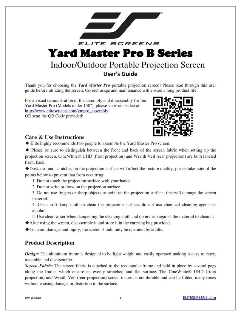
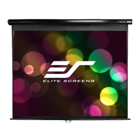
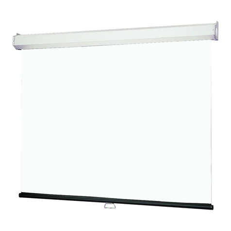
Beamax XL1200 User manual

Made by Adeo Screen sp. Z o.o. (Polska) for Home Cinema Modules
Specifications are subject to change without notice. E&OE
Doc: XL Series – HOME CINEMA MODULES Installation Manual rev3 | 21.05. 2013
Please verify that you are working with the latest revision of this document before specifying your screen.
Rohs Compliant
Mod. XL-SERIES
Code XL1200XL1299
Mod. XL-SERIES TENSIONED
Code XLT1500XLT1599
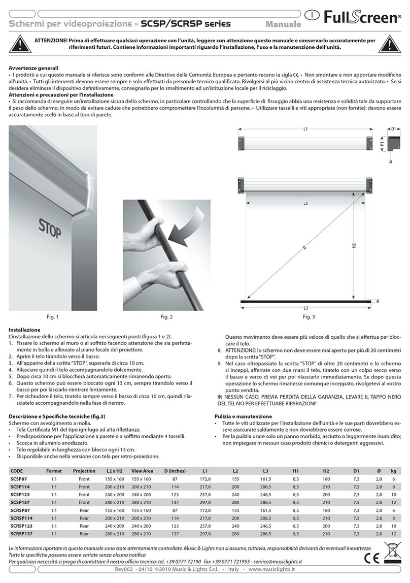
Manuale d’uso schermo avvolgibile
Projection screen user manual
Manuel d’instructions écran
Betriebsanleitung Projektionswand
Manual de uso de la pantalla enrollable
Instrukcja obsługi ekranu

ENGLISH – Motorized screen user manual
Specifications are subject to change without notice. E&OE
Doc: XL Series – HOME CINEMA MODULES Installation Manual rev3 | 21.05. 2013
Please verify that you are working with the latest revision of this document before specifying your screen.
Page
7
01 INTRODUCTION
This manual is an integral part of the product and must be read and understood in all its parts for safety reasons. It contains norms and directions for correct and safe use of the screen.
The manual should never be separated from the product; it must be stored in a suitable place to ensure its integrity, and in such a way as to be easily consulted by authorised personnel.
Product user shall be responsible for the manual’s safekeeping. User shall also be responsible for checking the screen’s functionality and for the repair or replacement of any damaged
parts that could pose a hazard.
Images contained in this manual are intended to provide a detailed description of the product’s functions, characteristics and procedures. Any slight difference, depending on the model
represented, will not change the meaning that the images convey.
02 GENERAL CHARACTERISTICS OF THE PRODUCT
T
he screen product is manufactured in compliance with the provisions of the following EC directives 2006-95-CE LDV
2004-108-CE EMC
1999-05-CE R&TTE
2005-32-CE Eco design
2011-65-CE ROHS
2002-96-CE RAEEi
2001-95-CE SAFETY
T
he screen described in this manual must be used exclusively as a support for video projection.
Any other use not covered by this manual, it is not consented.
T
he screen contains one or more Fabric of projection.
The Fabric of projection is a cadmium-free plastic pvc sheet or Glass wire (continuos filament) plastified PVC impregnated, any fabric
can be classified in
category:
- M1 and M2 fire classification under French standards (LNE Laboratoire national de métrologie et d’essais – SME Centre de recherches du Bouchet - WARRINGTONFIRE GENT Laboratoire de
métrologie et d’essais – IFTH Laboratoire accreditè
- B1 and B2 fire classification under German standards (LNE Laboratoire national de métrologie et d’essais – SME Centre de recherches du Bouchet - WARRINGTONFIRE GENT Laboratoire
national de métrologie et d’essais)
- UL94HB fire classification under USA standards (THE GOVMARK Organization, Inc.)
In the absence of a standardisation at a European level of the various national classification norms, it should be noted that the French M1 class corresponds to non flammable material and that M2 class
corresponds to flame retardant material.
03 UNPACKING AND HANDING THE SCREEN
Ensure that the screen has suffered no damage during transport. Should any fault be detected, promptly notify your dealer. Verify that all screen accessories have been included
Rolling screen UNDER 356 cm width Rolling
screen OVER 356 cm width
-2 installation brackets
-4 screws per bracket
-1 10° unipolar, 250V dead man’s selector switch with directional arrows, inclusive of wall mount
hood
-2 lateral brackets (for screen models without case)
-1 RF transmitter (for integrated radio screen models)
-1 plastic hex wrench
-1 instructions booklet
(screws and plugs for wall mount are not included)
-3 installation brackets
-6 screws per bracket
-1 10° unipolar, 250V dead man’s selector switch with directional arrow, inclusive of wall mount
hood-
-2 lateral brackets (for screen models without case)
1 RF transmitter (for integrated radio screen models)
-1 plastic hex wrench
-1 instructions booklet
(screws and plugs for wall mount are not included)
ATTENTION do not use cutters or sharp objects to open the wrapping, always use protection gloves when unpacking, handling and installing the product. Depending on the product’s weight (reference load:
25 Kg male – 15 Kg female), handling and installing operations should be performed by two, three or four people at least. For heavier loads we recommend the use of specific lifting equipment.
04 GENERAL SAFETY NORMS
Always read the instructions and warnings set out in this manual very carefully before using the product or before performing any maintenance interventions.
Installation of the screen above passageway is strictly forbidden.. Before and during use, check that the screen poses no risk of hazard.
Do not tamper with, remove or damage any part or component of the screen.
Never perform screen maintenance operations when the motor is on (for maximum safety, remove power supply).
Not children safe. It is mandatory to keep children away during operations with the screen.
All our screens are covered by guarantee; validity of the same shall be subject to user’s full compliance with the instructions contained in this manual.
WARNING: Faulty installation may compromise the safety of the product’s operators; manufacturer shall not be held liable for damages to persons or things resulting from faulty
installation, improper use, insufficient or inadequate maintenance of the screen.
Manufacturer shall not be held responsible for problems associated with installation errors.
Screen installation, electrical connections and verifications in case of malfunction of motorised rolling screens must be performed by authorised vendor or by personnel that is
informed and trained in electrical hazards. The connection cable cannot be replaced. If the cable is damaged the screen must be replaced. Tampering with end stops or piercing
the seal placed over holes shall entail the forfeiture of the guarantee. For any necessary clarifications please contact our technical office.
N.B.ONCE THE SCREEN HAS BEEN MOUNTED ON THE BRACKETS, AND PRIOR TO USING IT, USER IS MANDATORILY REQUIRED TO ENSURE THAT THE SCREEN’S POSITION IS
PERFECTLY HORIZONTAL.

ENGLISH – Motorized screen user manual
Specifications are subject to change without notice. E&OE
Doc: XL Series – HOME CINEMA MODULES Installation Manual rev3 | 21.05. 2013
Please verify that you are working with the latest revision of this document before specifying your screen.
Page
8
05 WARNINGS AND RECOMMENDATIONS FOR CORRECT USE
Our screens are suitable for indoor use at normal temperature (20 - 25 °C) and humidity conditions. Special precautions are necessary for outdoor use, especially as regards
temperature levels and the presence of dust. Exposure to temperatures of over 50 °C can cause permanent deformation of the screen’s flatness, or the screen to come away
from the roller.
Avoid prolonged exposure of the projection screen to solar light to prevent yellowing of the same (ensure that exposure to solar light does not cause the screen to reach said
temperature level).
Since electrostatic charge tends to accumulate on the projection screen (which is made of PVC), attracting dust, excessive dustiness in the projection environment can
deteriorate the optical quality of the screen (see projection screen cleaning instructions).
WARNING: Do not manually force the screen’s unrolling: this could result in the motor being damaged or the screen’s case to come away from the wall mount brackets.
Do not allow children to play with the screen’s control panel. Keep remote control out of children’s reach.
Monitor screen movement and allow no-one near it until it is completely closed.
The following operations: blocking, preventing or forcing the screen’s movement, hanging or swinging from it, adding or applying any object to the screen or backdrop,
modifying the screen’s structure – are strictly forbidden and could result in damages to the screen’s rolling system and ensuing hazard to persons and things.
06 CLEANING AND MAINTENANCE
Screens and their projection surfaces are delicate and must be cleaned with great care, according to the following instructions:
Never use solvents, chemical or abrasive products, or pointed tools to clean the surface.
Avoid contact with other materials (varnishes, inks etc) as they might be impossible to remove from the canvas.
FABRIC MATT WHITE, HIGH CONTRAST, 3D WHITE:
Remove dust from the case with a soft, clean cloth and a non aggressive detergent as necessary.
Clean the projection screen with a soft, clean, damp cloth, and a neutral or alcohol-base detergent as necessary. Since rubbing the screen with a cloth during cleaning operations can cause electrostatic
charge to accumulate, we recommend the subsequent application of an antistatic liquid with a clean cloth, to avoid dust being attracted again
GENERIC PROFILE: Remove dust from the case with a soft, clean cloth and a non aggressive detergent as necessary
VELVET PROFILE: Clean profile with a soft clean cloth, or a brush with soft, antistatic bristles. A vacuum-cleaner brush may be used, provided its bristles are soft and perfectly clean.
STRUCTURE and ANCHORING BRACKETS:
The state of the product and the anchoring capacity of its brackets must be checked regularly. In case of canvas deformation or rips, or loosening of structural
components such as brackets or screws, action must be taken immediately to clear the area around the screen and avoid hazard to people and things, replace the defective component and restore the
product's functionality.
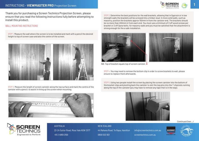
07 INSTALLATION INSTRUCTIONS
WARNING: It 's absolutely forbidden to install the screen on mobile walls or unstable cables,the brackets must be applied on surfaces that ensure in the time your distance. When
installing the screen use plugs and screws suitable for the screen’s weight and for the type of wall or ceiling on which the mount brackets are to be fixed, based on the following criteria
Screen width up to cm 160
200
250
300
360 410 520
620
Overall weight Kg 20
Kg 25
Kg 30
Kg 35
Kg 45 Kg 50 Kg
100
Kg 150
Secure the brackets to the ceiling or wall considering a maximum distance of 5 cm from the screen’s lateral edges, as shown in the picture on the left.
CEILING INSTALLATION
Proceed as described in picture 1, bring the screen close to the brackets (pos.1); block the rear part of the screen by tilting it slightly (pos.2); push the screen upwards until it
slides into the bracket (pos.3); tighten the three screws on the bracket as far as they will go (pos.4).
WALL INSTALLATION
Proceed as described in picture 2, bring the screen close to the brackets (pos.1); block the rear part of the screen by tilting it slightly (pos.2); push the screen upwards until it
slides into the bracket (pos.3); tighten the three screws on the bracket as far as they will go (pos.4).
FIG. 1 FIG. 2

ENGLISH – Motorized screen user manual
Specifications are subject to change without notice. E&OE
Doc: XL Series – HOME CINEMA MODULES Installation Manual rev3 | 21.05. 2013
Please verify that you are working with the latest revision of this document before specifying your screen.
Page
9
V
ERSION WITHOUT CASE
1) Important: make absolutely sure that the motor and the end cap of the pivot are correctly inserted into the roller, as transportation can sometimes cause them to become dislodged and to protrude
slightly from their original position.
2) Check the distance of the two side brackets mounted on the screen. Then dismantle the bracket on the side of the motor by loosening the two lateral screws, and the bracket on the pivot side afte
r
removing the metal cotter pin to release the pivot.
3) Then mount the two brackets on the wall or ceiling at exactly the same distance previously checked, using suitable toggle bolts for the surface on which the screen is to be installed.
4) Mount the screen on the brackets by inserting the screws on the motor and pivot sides, and blocking the pivot with the metal cotter pin provided.
08 COUNTERWEIGHT TENSIONING ADJUSTAMENT
09 MOTOR TYPE IDENTIFICATION –CHARACTERISTICS – ELECTRICAL CONNECTION
The type of motor installed on the product is identified by a label applied on each product showing the CE logo. When unwrapping the product please check the model type indicated on the label in order to
perform the installation and cable connections correctly. Should the power of the motor be different from that of the supply network of the installation place, please contact an electrician to have a current and
Hz transformer installed.
ELECTRICAL CONNECTION:
electric cabling must be conformant with applicable IEC standards. IEC norm EN 60335-1 requires that supply network be fitted with an omnipolar selector
switch with contact opening distance of at least 3 mm. For the screen’s control use only the selector switch provided by manufacturer, or equivalent model,
and follow the instructions of the connection diagram shown on left (if the motor is mounted on the left, the colours of the wires must be inverted, i.e.
descending = brown, ascending = black). The selector switch must be mounted within sight distance of the product, at a 1.5 - 1.8 m height from the floor. To
connect the wires to the supplied switch, remove the plastic front plates to access the lock/unlock buttons
WARNING:
Correctly performed, state-of-the-art, norm-compliant electrical connections are important to prevent accidents and to ensure the screen’s optimal and
unaltered performance over time. Prior to carrying out any operation on electrical parts ensure that power supply is disconnected. In screens fitted with cases
the motor is positioned on the right-hand side of the screen as seen from the front (upon request it can be located on the left). Never connect two or more
motors to the same selector switch without a control unit or two switches to the same motor.
230V 50Hz
Motor characteristics:
Frequency: ~Hz50
Power: 170W
Torque: 15Nm
Speed: 17Rpm
Max no. of cycles: 2
Cable length: 3mt
Mechanical strength:
EN14202 conformant
Operating T°:
from –20 to +55 °C
Connection for each motor:
Brown (Up)
Black (Down)
Blue (Common)
Yellow Green (Ground 230V)

ENGLISH – Motorized screen user manual
Specifications are subject to change without notice. E&OE
Doc: XL Series – HOME CINEMA MODULES Installation Manual rev3 | 21.05. 2013
Please verify that you are working with the latest revision of this document before specifying your screen.
Page
10
ELECTRICAL CONNECTION:
electric cabling must be conformant with applicable IEC standards. IEC norm EN 60335-1 requires that supply network be fitted with an omnipolar selector
switch with contact opening distance of at least 3 mm. For each motor (e.g. plug switch etc.). In case of need, this device ensures that the power supply is
safely and quickly cut off. Use the wires as described in the figure.
WARNING:
Correctly performed, state-of-the-art, norm-compliant electrical connections are important to prevent accidents and to ensure the screen’s optimal and
unaltered performance over time. Prior to carrying out any operation on electrical parts ensure that power supply is disconnected.
Bus cables (black white orange) must be insulated if not used for the push-button command.
In screens fitted with cases the motor is positioned on the right-hand side of the screen as seen from the front.
Operates with standard radio control (supplied).
Somfy RTS 230V 50Hz
Technical characteristics:
Frequency: ~Hz50
Power: 140W
Torque: 15Nm
Speed: 17Rpm
Max no. of cycles:
2
Operating T°:
from –20 to +55 °C
Frequency: 433.92 MHz
Trans. range: 150mt
Connection for each motor:
Brown (Phase 230V)
Blue (Neutral 230V)
Yellow Green (Ground 230V)
10 END STOP MOTOR ADJUSTMENT
WARNING - READ CAREFULLY BEFORE PERFORMING ADJUSTMENTS
Adjustments shown in the following table must be performed by authorised and specialised personnel only. Incorrect performance of the procedures described may result in
damages to the product which will not be covered by guarantee. End stops adjustment varies depending on the motor’s position (left side A column - right side B column) or on
drop of the curtain (rear line C – front line D). Adjustment is performed with a 4 mm hex wrench (included).
END STOPS ADJUSTMENT SCREWS ARE POSITIONED IN THE BOTTOM PART OF THE SCREEN, AND NOT IN THE RIGHT OR LEFT HAND SIDES. DO NOT ADJUST THE END STOPS
WHEN UP OR DOWN BUTTON IS ACTIVATED.
WARNING
“UPPER END STOP MUST ALWAYS BE ADJUSTED AT 2mm FROM THE CASE” see picture on the right.
End stop is adjusted so as to allow the projection sheet to wind around the roller at least 1.5 times to avoid the sheet coming loose. Special attention must be paid when end
stops are adjusted in such a way that projection sheet unwinds beyond the factory setting. This is allowed within a limit of 3 cm without posing a risk to the product. Incorrect
adjustment of end stops can cause:
-Projection sheet coming away from the roller
-Projection sheet winding the wrong way, with ensuing damage to flatness of the projection surface and to winding mechanisms
-Breaking of bottom end black frame welding (framed screens)
-Excessive strain on motor with possible ensuing damage and activation of motor’s thermal resistance
-Excessive winding of the end stop adjustment system with ensuing breaking of the mechanical part
WARRANTY
Operators are reminded that in cases where seals have been tampered with and where any damages have resulted from incorrect adjustment, repair interventions shall not be
covered by guarantee.
A – Left Motor B –
Right Motor (standard)
Back fall
-
C
Frontal fall
-
D

ENGLISH – Motorized screen user manual
Specifications are subject to change without notice. E&OE
Doc: XL Series – HOME CINEMA MODULES Installation Manual rev3 | 21.05. 2013
Please verify that you are working with the latest revision of this document before specifying your screen.
Page
11
PROGRAMMING END STOPS MOTOR SOMFY RTS 230V 50Hz/120V 60Hz (procedures already carried out in factory, SHOULD NOT be performed by unauthorised personnel)
Down limit switch
1
Move the
screen surface
to down limit
switch.
2
Press both
and at the
same time until you will see
a brief up and down motion
of screen surface.
3
Move the screen with
buttons
and
to reach the desired
down limit position.
4
Press button until you
will see a brief up and down
motion of screen surface to
memorize the new position
Up limit swicht
1.
Move the
screen surface
to up limit
switch.
2
Press both
and at the
same time until you will see
a brief up and down motion
of screen surface.
3
Move the screen with
buttons
and
to reach the desired up
limit position.
4
Press button until you
will see a brief up and down
motion of screen surface to
memorize the new position
PRODUCT’S DISPOSAL
As is the case for installation procedures, when the product reaches the end of its useful life, disposal operations must be carried out by qualified personnel.
The product is made up of various types of material: some can be recycled, others have to be disposed of. You must follow applicable recycling or disposal regulations in
force in your area for this product category.
As shown in the picture on the left, you must not throw the product into a domestic litter bin. Either dispose of the various components separately, pursuant to the
regulations applicable in your territory, or hand the product over to a vendor upon purchasing a similar new product.
Warning: local regulations can foresee heavy fines in case of unlawful disposal of this product.
GUARANTEE
1.GUARANTEE LIMITATIONS The Manufacturer guarantees that all the products it distributes are free of production-, material- and processing-related defects, without prejudice to the following terms and
conditions:
* The product is guaranteed for a period of twenty-four (24) months
* Mechanical parts are guaranteed for a period of thirty-six (36) months
* The motors and remote controls (excluding batteries) are guaranteed for a period of thirty-six (36) months
as from the date of the purchase invoice/receipt released to the end user
2.CONDITIONS AND LIMITATIONS This guarantee is subject to the following conditions and limitations:
the guarantee shall be deemed null and void if: the product has been used or manipulated in any manner other than those indicated in the user manual’s instructions; or damaged as a result of improper use,
or owing to accident or negligence during transport; or if the product’s defect is the result of repair or manhandling on the part of anyone other than personnel authorized by our Customer Care office.
T
he product must be installed by trained and experienced insider professionals, following the instructions provided for the installation and maintenance procedures.
3.RETURNS No product shall be returned and accepted without an authorization (RMA) released by Customer Care.
Products must be returned in their original (or equivalent) packaging to avoid being damaged during transport. Any transport damages resulting from inappropriate packaging shall not be covered by this
guarantee.
T
he returned product shall be accompanied by a detailed description of the defect and by a photocopy of the original purchase invoice/receipt.
T
he purchase invoice/receipt shall clearly indicate the following: Model
–
Serial number
–
Purchase
date
–
Name and address of
the
purchaser and authorized dealer.

Specifications are subject to change without notice. E&OE
Doc: XL Series – HOME CINEMA MODULES Installation Manual rev3 | 21.05. 2013
Please verify that you are working with the latest revision of this document before specifying your screen.
Page
32
Dear User,
Thank you for purchasing a Beamax® projection screen.
This projection screen is hand built using the finest quality materials with meticulous attention to detail.
Therefore we trust this screen will offer you the utmost. Whether you use it for home cinema or business purposes, it
will give you the ultimate experience.
Most kind regards,
The Beamax® Team
De Dolfijn 20-22
1601 MG Enkhuizen
The Netherlands
+31228 – 748100
UK: 0845 52 800 96
www.beamax.com
This manual suits for next models
3
Other Beamax Projection Screen manuals

