manuals.online logo
Brands
  1. Home
  2. •
  3. Brands
  4. •
  5. Screen Technics
  6. •
  7. Projection Screen
  8. •
  9. Screen Technics ViewMaster Pro User manual

Screen Technics ViewMaster Pro User manual

I
N
A
U
S
T
R
A
L
I
A
P
R
O
U
D
L
Y
B
U
I
L
T
1
Continued Over.../
INSTRUCTIONS - VIEWMASTER PRO Projection Screen
STEP 1. Measure the wall where the screen is to be installed and mark with a pencil the desired
height to top of screen case and also the centre of the screen.
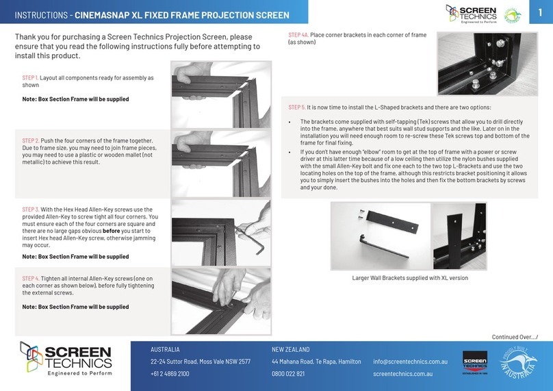
STEP 4. You may need to remove the bottom clip in order to screw brackets to wall, please
ensure to replace them afterwards.
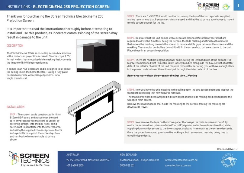
STEP 5. Using two people install the screen by placing the screen canister into the bottom of
the bracket clips and pivoting back the canister to slot the top pins into the T channels running
along the top of the canister (you may have to remove any tape that is in the way).
STEP 3. Determine the best positions for the wall brackets, allowing that in Gyprock or in low
strength walls the brackets will be screwed into a timber stud. In more solid walls, such as
masonry, position the brackets approx 150mm in from the canister end. The brackets should
be no more than 450mm in from each end. You must use a minimum of 3 off wood screws per
bracket or 2 off Dyna-bolts, for masonry walls and you must be satised that the attachment is
strong enough for the a safe installation.
Thank you for purchasing a Screen Technics Projection Screen, please
ensure that you read the following instructions fully before attempting to
install this product.
WALL MOUNTING INSTRUCTIONS

-�  SCREEn
TECHnlCS
CINEMAPRO Hanging Type Projection Screen


 
       

 

    
          
         
       
                

STEP 2. Measure the length of screen canister along the top surface and mark the centre of the
canister with a pencil, to assist in lining up the screen when mounting.
NB: Top of bracket equals top of screen canister.
info@screentechnics.com.au
screentechnics.com.au
AUSTRALIA
22-24 Suttor Road, Moss Vale NSW 2577
+61 2 4869 2100
NEW ZEALAND
44 Mahana Road, Te Rapa, Hamilton
0800 022 821
I
N
A
U
S
T
R
A
L
I
A
P
R
O
U
D
L
Y
B
U
I
L
T
ESTABLISHED IN 1990
I
N
A
U
S
T
R
A
L
I
A
P
R
O
U
D
L
Y
B
U
I
L
T
2
INSTRUCTIONS - VIEWMASTER PRO Projection Screen
STEP 6. Holding screen in position tighten up
Allen screw at each end and check that the
top pins have hooked into the T section of
the screen canister.
STEP 7. Ensure projection screen is latched
into the bracket as shown.
HANGING MOUNT INSTRUCTIONS (Requires optional eye bolts)
See photo showing a side view using the brackets for hanging, two hanging rings are optional;
attach the brackets to the canister as per point 6 in instructions.
Please ensure the hanging points are secured to a suitable structure.
• Ensure that the screen is free to descend and that any adhesive tape that has been placed
at the bottom of the screen (to stop movement during transport) has been fully removed.
• When installed, the opening in the canister should be down and at the back of the canister.
This will put the chain drive on the left-hand side of the screen, as viewed by the audience.
(Unless ordered otherwise).
• Cleaning of the screen is best achieved by rst dusting the surface with a feather duster,
then to remove any stubborn marks, use a small amount of mild detergent and warm water
on a clean white lint free cloth. Do not use a saturated cloth, as this may leave a watermark,
only a damp one. It is most important that you only treat the actual mark by this process
and not the entire surface
• The Motor is 240 V 50Hz and draws 1.2 A.
• The screen drop is set and tested at the factory. Therefore, any damage caused to the
screen from limit re-adjustment is not covered by warranty.
Should you have any questions regarding the installation of our projection screens please call
our technical sales desk on +61 2 4869 2100 for assistance.
Please follow these instructions to ensure trouble free operation;
CEILING MOUNT INSTRUCTIONS
Below is a photo showing a side view using the brackets for ceiling xing, you would follow the
instructions for the wall mounting system, with the only difference being the screen is mounted
hard against the ceiling. It is important that adequate support is supplied by the ceiling
structure to support the screen and to ensure a safe installation. Never rely just on the Gyprock
for attachment.
Hanging Mount Instructions (Requires optional eye bolts)
See photo showing a side view using the brackets for
hanging, two hanging rings are optional; attach the
brackets to the canister as per point 6 in instructions.
Please ensure the hanging points are secured to a
suitable structure.
Please follow these instructions to ensure trouble free operation;
Ensure that the screen is free to descend and that any adhesive tape that has been placed on the
bottom of the screen (to stop movement during transport) has been removed.
When installed, the opening in the canister should be down and at the back of the canister. This will put
the motor on the left-hand side of the screen, as viewed by the audience.
Cleaning of the screen is best achieved by first dusting the surface with a feather duster, then to remove
any stubborn marks, use a small amount of mild detergent and warm water on a clean white lint free
cloth. Do not use a saturated cloth, as this may leave a watermark, only a damp one. It is most
important that you only treat the actual mark by this process and not the entire surface.
The Motor is 240 V 50Hz and draws 1.2 A.
The screen drop is set and tested at the factory. Therefore, any damage caused to the screen from limit
re-adjustment is not covered by warranty.
Continued Over.../
I
N
A
U
S
T
R
A
L
I
A
P
R
O
U
D
L
Y
B
U
I
L
T
3
INSTRUCTIONS - VIEWMASTER PRO Projection Screen
Continued Over.../
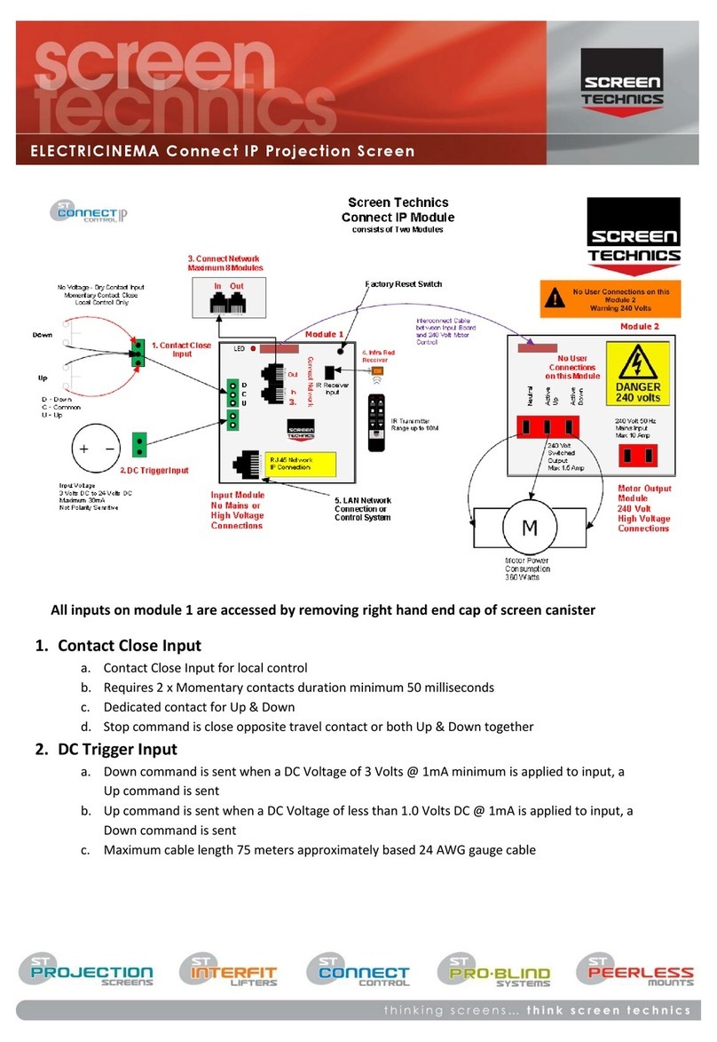
1. CONTACT CLOSE INPUT
• No voltage, dry contact input
• Requires momentary contact only
• Contact is closed and opened between Up & Common – screen moves to up limit
• Contact is closed and opened between Down & Common – screen moves to bottom limit
• Stop command is sent when both Up & Down contact closed together
• Motor reverses travel when opposite contact is closed – if moving down and up contact is
closed screen will stop and then reverse direction
• Stop command is sent when both Up & Down contact closed together
2. INFRA-RED RECEIVER
• Packaged with 300mm and 1.2 M lead from motor board to IR receiver
• Packaged with standard 2 channel IR transmitter
• Screen operates on group 1 & 2 on infra-red remote
• Green LED 1 on motor board will ash when IR commands are received
3. DC TRIGGER INPUT
• Down command is sent when a DC Voltage above 1.5 Volts @ 1mA minimum is applied to
trigger input
• Up command is sent when a DC Voltage below 1.5 Volts @ 1mA minimum is applied to the
trigger input
• Trigger input is polarity sensitive
• DC voltage must not exceed 15 Volts DC
Note: The Viewmaster pro is equipped with automatic retraction after power failure, if power is
lost to the screen, the surface will retract to the up position when power is reconnected
MasterFit IP A, A+, B, B+, C, C+ Projection Screen
Thank you for purchasing a Screen Technics Projection Screen, please ensure that you read
the following instructions fully before installing this product.
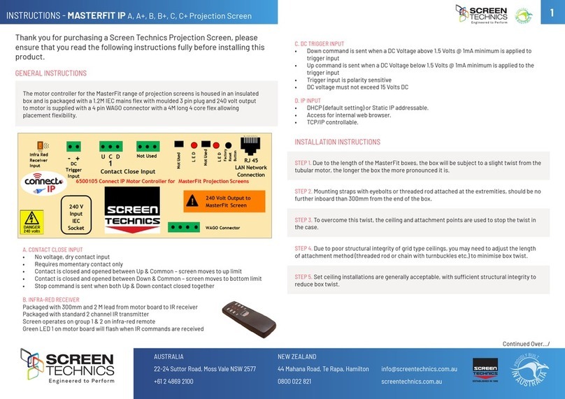
The motor controller for the MasterFit range of projection screens is housed in an insulated
box and is packaged with a 1.2M IEC mains flex with moulded 3 pin plug and 240 volt output
to motor is supplied with a 4 pin WAGO connector with a 4M long 4 core flex allowing
placement flexibility.
1. Contact Close Input
No voltage, dry contact input
Requires momentary contact only
Contact is closed and opened between Up & Common – screen moves to up limit
Contact is closed and opened between Down & Common – screen moves to bottom limit
Stop command is sent when both Up & Down contact closed together
2. Infra-Red Receiver
Packaged with 300mm and 1.2 M lead from motor board to IR receiver
Packaged with standard 2 channel IR transmitter
Screen operates on group 1 & 2 on infra-red remote
Green LED 1 on motor board will flash when IR commands are received
Access to control board is on left hand side of projector screen case
Power must be removed before accessing inputs on control board
1. Contact Close Input
No voltage, dry contact input
Requires momentary contact only
Contact is closed and opened between Up & Common – screen moves to up limit
Contact is closed and opened between Down & Common – screen moves to bottom limit
Motor reverses travel when opposite contact is closed – if moving down and up contact is closed
screen will stop and then reverse direction
Stop command is sent when both Up & Down contact closed together
2. Infra-Red Receiver
Packaged with 300mm and 1.2 M lead from motor board to IR receiver
Packaged with standard 2 channel IR transmitter
Screen operates on group 1 & 2 on infra-red remote
Green LED on motor board will flash when IR commands are received
3. DC Trigger Input
Down command is sent when a DC Voltage of 1.5 Volts @ 1mA minimum is applied to trigger input
Up command is sent when a DC Voltage below 1.5 Volts @ 1mA minimum is applied to the trigger input
Trigger input is polarity sensitive
DC voltage must not exceed 15 Volts DC
Note: The Viewmaster pro is equipped with automatic retraction after power failure, if power is lost to the
screen, the surface will retract to the up position when power is reconnected
Access to control board is on left hand side of projector screen case.
Power must be removed before accessing inputs on control board.
LIMIT SETTING FOR VIEWMASTER PRO SCREENS
The following instructions are for the adjustment of the limit switches that alter the upper
and lower stop positions on “Connect” ElectriCinema Screens only
WHERE ARE THE LIMIT SWITCHES?
(On the Left Hand Side).
One switch is accessible through the slat rod opening and the other is behind round cover plug
towards the front of the canister.
WHICH SWITCH IS FOR UP AND DOWN?
Down switch - Accessible through the round cover plug
Up switch - Accessible through the slat rod opening
WHAT TOOLS DO I NEED?
Either the limit setting tool (supplied), a narrow tip
screw driver (less than 4mm) or a 4mm Allen Key
RJ12 6 Core Straight Through Data cable can link up to 8 Connect controlled devices for multiple switching.
Low Voltage Trigger
Switches device upon the receipt of 3v to 24v DC from a projectors low volt output port, plugs into the phoenix
connector on the module.
Not polarity sensitive.
IP Control RJ45
Due to the detailed nature of the user instructions associated with this method of control we direct you to the
associated document – Electricinema IP Control Instructions V1.0
However for a beginners guide to basic control functions please download from www.screentechnics.com.au
the PC Connect or Mac Connect software and this will assist you in identifying the Connect Module and provide
basic control, then guide you by web browser to communicate and program the individual Module.
Note: You will have to connect the screen module to a network to be able to utilise this software.
Note: As the Infra-Red control is also used to perform a Connect module reset in case you are troubleshooting any performance
issues, it is recommended that the IR cable be left attached to the module even if it is not the chosen operating method for your
installation.
Limit Setting for Connect ElectriCinema Screens
The following instructions are for the adjustment of the limit switches that alter the upper
and lower stop positions on "Connect" ElectriCinema Screens only
Where are The Limit Switches?
At the opposite end to the power cable (ie on the Right Hand Side).
One switch is accessible through the slat rod opening and the other is behind a rubber grommet
towards the front of the canister.
Which Switch is for Up and Down?
Down switch - Accessible through the rubber grommet
Up switch - Accessible through the slat rod opening
What Tools do I Need?
Either the limit setting tool (supplied), a narrow tip screw driver (less than 4mm) or a
4mm Allen Key
Which Way do I Turn the Switch?
Clockwise always increases the amount of rotation (travel) of the motor.
Anti-clockwise always reduces the amount of rotation (travel) of the motor.
So pick the switch responsible for the limit position, up or down. Clockwise turning of the switch will always let the motor travel
further in that direction. Anti-clockwise turning of the switch will lessen the amount of travel in that direction.
Can I adjust the switch while the screen is sitting on the limit - ie fully up or down?
Clockwise adjustment? – YES. But it is better to back the screen away from the limit and then adjust
Anti-clockwise adjustment? - NO you will damage the micro switch if you turn it anti-clockwise while the screen is sitting on the limit.
Never attempt this. You must back the screen away from the limit
before adjustment. After adjustment you will need to run the screen up and down to pick up the new limit
Will I void the product warranty if I damage the screen whilst making these adjustments?
Yes.
I
N
A
U
S
T
R
A
L
I
A
P
R
O
U
D
L
Y
B
U
I
L
T
4
INSTRUCTIONS - VIEWMASTER PRO Projection Screen
WHICH WAY DO I TURN THE SWITCH?
Clockwise always increases the amount of rotation (travel) of the motor.
Anti-clockwise always reduces the amount of rotation (travel) of the motor.
So pick the switch responsible for the limit position, up or down. Clockwise turning of the
switch will always let the motor travel further in that direction. Anti-clockwise turning of the
switch will lessen the amount of travel in that direction.
CAN I ADJUST THE SWITCH WHILE THE SCREEN IS SITTING ON THE LIMIT - IE FULLY UP OR DOWN?
Clockwise adjustment? – YES. But it is better to back the screen away from the limit and then
adjust
Anti-clockwise adjustment? - NO you will damage the micro switch if you turn it anti-clockwise
while the screen is sitting on the limit. Never attempt this. You must back the screen away from
the limit before adjustment. After adjustment you will need to run the screen up and down to
pick up the new limit
WILL I VOID THE PRODUCT WARRANTY IF I DAMAGE THE SCREEN WHILST MAKING THESE ADJUSTMENTS?
YES.!!!
Should you have any questions regarding the installation of our products please call our sales
desk on +61 2 4869 2100 for assistance
BEWARE
ROLLERS SCREENS HAVE A FINITE AMOUNT OF LEADER, THE STANDARD BEING 300MM.
IF YOU ORDER A CUSTOM LEADER LENGTH THEN THAT BECOMES THE FINITE AMOUNT.
DO NOT ADJUST THE BOTTOM LIMIT SO AS TO EXPOSE MORE THAN THIS FINITE AMOUNT
IF YOU DO YOU WILL:
EXPERIENCE POOR LAYFLAT OF THE SURFACE WHICH MAY BRING COMPLAINTS FROM YOUR CUSTOMER.
WEAKEN THE HOLD OF THE SURFACE ON THE ROLLER AND, ONE DAY, THE SURFACE WILL BE ON THE FLOOR.
THIS IS NOT COVERED UNDER WARRANTY

Other Screen Technics Projection Screen manuals

Screen Technics ELECTRICINEMA User manual

Screen Technics

Screen Technics ELECTRICINEMA User manual

Screen Technics ELECTRICINEMA User manual

Screen Technics

Screen Technics ELECTRICINEMA User manual

Screen Technics ELECTRICINEMA 235 User manual

Screen Technics

Screen Technics ELECTRICINEMA 235 User manual

Screen Technics CINEMATECH User manual

Screen Technics

Screen Technics CINEMATECH User manual

Screen Technics ELECTRICINEMA User manual

Screen Technics

Screen Technics ELECTRICINEMA User manual

Screen Technics CinemaSnap Series User manual

Screen Technics

Screen Technics CinemaSnap Series User manual

Screen Technics CINEMASNAP 235 User manual

Screen Technics

Screen Technics CINEMASNAP 235 User manual

Screen Technics ELECTRICINEMA A User manual

Screen Technics

Screen Technics ELECTRICINEMA A User manual

Screen Technics MASTERFIT IP User manual

Screen Technics

Screen Technics MASTERFIT IP User manual

Screen Technics ELECTRICINEMA 235 Guide

Screen Technics

Screen Technics ELECTRICINEMA 235 Guide

Screen Technics ELECTRICINEMA A User manual

Screen Technics

Screen Technics ELECTRICINEMA A User manual

Screen Technics CINEMAPRO User manual

Screen Technics

Screen Technics CINEMAPRO User manual

Screen Technics TRAPDOOR User manual

Screen Technics

Screen Technics TRAPDOOR User manual

Screen Technics CINEMASNAP XL User manual

Screen Technics

Screen Technics CINEMASNAP XL User manual

Screen Technics ELECTRICINEMA User manual

Screen Technics

Screen Technics ELECTRICINEMA User manual

Popular Projection Screen manuals by other brands

Elite Screens Spectrum Tab-Tension Series user guide

Elite Screens

Elite Screens Spectrum Tab-Tension Series user guide

Speaka Professional 2357532 Important information

Speaka Professional

Speaka Professional 2357532 Important information

Da-Lite PRO IMAGER Instruction book

Da-Lite

Da-Lite PRO IMAGER Instruction book

Da-Lite Viewshare Advantage Electrol Instruction book

Da-Lite

Da-Lite Viewshare Advantage Electrol Instruction book

Draper 220V Envoy Installation & operating instructions

Draper

Draper 220V Envoy Installation & operating instructions

Elite Screens DE103C82H user guide

Elite Screens

Elite Screens DE103C82H user guide

Mustang Pocketscreen Assembly instruction

Mustang

Mustang Pocketscreen Assembly instruction

STILFORD JBSC121WBK Assembly instructions

STILFORD

STILFORD JBSC121WBK Assembly instructions

LUMENE Movie Palace 200C user manual

LUMENE

LUMENE Movie Palace 200C user manual

Draper Envoy Installation & operating instructions

Draper

Draper Envoy Installation & operating instructions

Elite Screens DIY Screen Series user guide

Elite Screens

Elite Screens DIY Screen Series user guide

Barco R9840400 installation manual

Barco

Barco R9840400 installation manual

Monoprice 7931 user manual

Monoprice

Monoprice 7931 user manual

Celexon Ultra mobile professional operating instructions

Celexon

Celexon Ultra mobile professional operating instructions

Elite Screens Daywalker Series user guide

Elite Screens

Elite Screens Daywalker Series user guide

Napoleon SF30 Assembly/installation instructions

Napoleon

Napoleon SF30 Assembly/installation instructions

J.Burrows Stilford JBSC181WBE Assembly instructions

J.Burrows

J.Burrows Stilford JBSC181WBE Assembly instructions

Elite Screens FE72V user manual

Elite Screens

Elite Screens FE72V user manual

manuals.online logo
manuals.online logoBrands
  • About & Mission
  • Contact us
  • Privacy Policy
  • Terms and Conditions

Copyright 2025 Manuals.Online. All Rights Reserved.