Beaumont LC10 Manual

1/2019
Installation, Operation, and
Maintenance Instructions
www.beaumontmanufacturing.com Model LC10
Specifications
Connections:
Threaded: 1 1/2” and 2”
Flanged: 2” to 8”
Union: 4” and 5”
Pressure Rating:
Threaded: 6000 psi
Flanged: Up to ANSI 2500 Class
Union: 1500 psi
Temperature Range:
-50° F to 400° F (Varies by Material Selections)
Pilot Connections: 1/4” NPT
Pilot Max Pressure: Limited by Gauges
Electric Switch Ratings:
SPDT: 15 A @ 125, 250, 480 VAC
DPDT: 10 A @ 125 VAC
Application
The LC10 is a liquid level controller. It uses a displacer balanced by a
spring to detect the level of a liquid inside a vessel. As the liquid level
rises and falls the LC10 gives either an increasing or decreasing
output signal using a pneumatic pilot or electric switch.
The LC10 is available with many different options making it an
extremely versatile device that can be set up in a variety of ways.
Three different pneumatic pilots options are available as well as two
electric switch options. Left hand, right hand, and back mount
options are available to fit a variety of vessels and piping layouts.
Many different connections sizes, arm lengths, displacer sizes and
materials make for an endless combination of available models to fit
almost any need.
Many of the options of the LC10 are able to be changed right in the
field. The pilots can be easily removed from the LC10 making it easy
to change them out in the field. The standard LC10 can be swapped
from right to left hand or vice versa in the field. The LC10 can also be
changed from direct to reverse acting in the field. The displacer and
arm can also be easily swapped out at any time or changed from a
horizontal to vertical orientation.
LC10B
LC10/
LC10S

1/2019
Installation, Operation, and
Maintenance Instructions
www.beaumontmanufacturing.com Model LC10 Installation
Installation
Arm and Displacer (See Figure 1)
The Arm and Displacer are shipped in the box with the LC10 and will
need to be attached before the LC10 is installed into a vessel. Thread
the Arm into the Shaft inside the LC10 Body. This can be done
inserting the Arm into the hole in the end of the LC10 Body and
pushing it in until it can be threaded into the hole in the Shaft located
near the back of the Body. The Shaft may need to be rotated slightly
until the threaded hole is aligned to the front. For a horizontal
arrangement screw the Displacer directly onto the Arm. For a vertical
arrangement, attach the Arm followed by the Swivel Assembly, then
add the Displacer. If vibration is a concern, Loctite can be added to
the Arm threads before installation.
Body
For a threaded Body verify that the condition of the threads on the
vessel and the LC10 are undamaged and free of debris. Apply pipe
compound or Teflon tape to the threads. Insert the Displacer and Arm
into the vessel and thread the LC10 onto the vessel.
For a flanged Body LC10 use the correct Gasket and bolts to connect
the LC10 to the vessel.
For a union connection be sure to put the Hammer Nut over the Body
before threading the LC10 Body into the blind flange. Then put the
blind flange on the end of the Weld Neck and thread on and tighten
the Hammer Nut.
For any installation make sure that there is enough clearance for the
Arm and Displacer to move freely in the vessel without touching the
vessel sides or bottom.
Pilot/Switch (See Figure 3)
Connect low pressure supply gas to the LC10 Pilot. The 1/4 NPT Pilot
connections can be found at the back of the LC10 Case. CAUTION:
Be sure not to exceed the pressure range of the Pilot Gauges.
Doing so can damage the gauges and pilot. The standard Gauges
are 0-30 or 0-60 psi.
If installing an LC10 with an Electric Switch, follow the proper
electrical codes when making connections and installing conduit. See
Figure 2.
Figure 2 Figure 3
Figure 1

1/2019
Installation, Operation, and
Maintenance Instructions
www.beaumontmanufacturing.com Model LC10 Operation
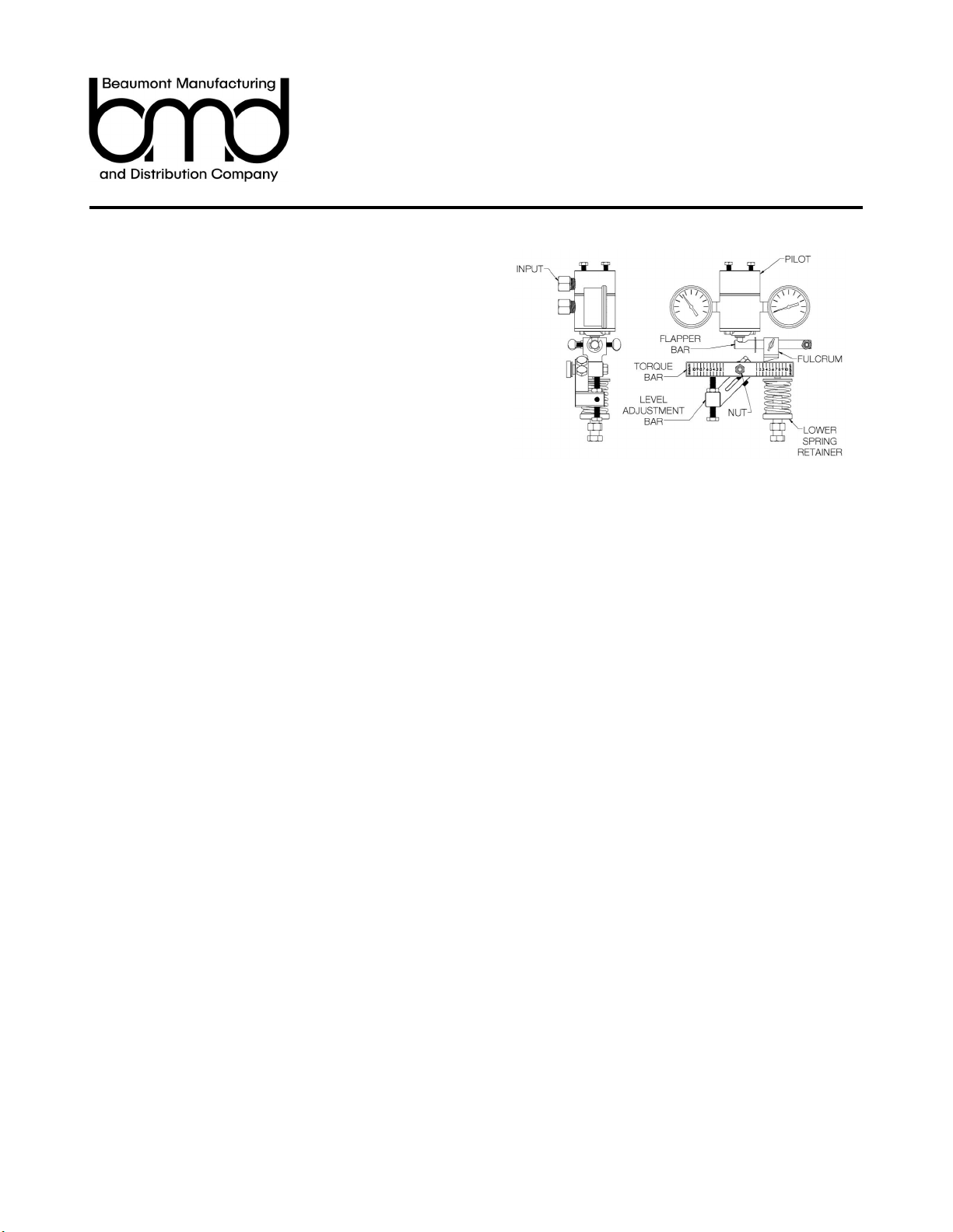
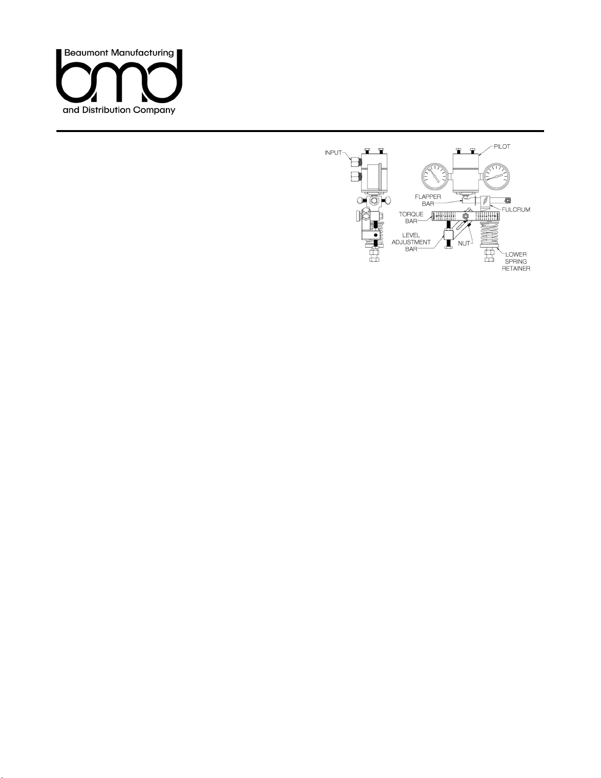
Principles of Operation
The LC10 uses Archimedes' principle in order to detect the level of
liquid in a vessel. The Displacer weighs less when submerged in a
liquid, because of the buoyant force acting on the Displacer when it is
submerged. Since the weight of the Displacer is balanced by the
LC10 Spring, the buoyant force from the liquid is enough to lift the
Displacer and Arm upward rotating the Level Adjustment Bar. The
Level Adjustment Bar pushes on the Torque Bar which acts upon the
Fulcrum on the Level Adjustment Bar. The Level Adjustment Bar then
pushes the Pilot Pin triggering the Pilot.
Level Adjustment
When using an LC10 with a vertical Displacer orientation, the liquid
level in the vessel can be adjusted by turning the Lower Spring
Retainer as shown in Figure 4. Turning the Lower Spring Retainer
changes the amount of load provided by the Spring which in turn
changes the amount of support provided to the Displacer’s weight.
Turning the Lower Spring Retainer clockwise provides less spring load
and less offset of the displacers weight. This means that the liquid will
have to rise higher on the Displacer in order to lift it and trigger the
LC10. Turning the Lower Spring Retainer counter-clockwise provides
more spring load meaning the liquid level does not need to rise as
high on the Displacer to trigger the LC10. Therefore turning the Lower
Spring Retainer clockwise raises the liquid level in the vessel, and
turning it counter-clockwise lowers the level.
Note that amount that the level can be adjusted is limited by the
length of the Displacer.
Direct vs Reverse Acting (See Figure 6)
A direct acting LC10 arrangement will increase the Pilot output as the
Displacer is lifted. Reverse acting arrangement will decrease the Pilot
output as the Displacer is lifted.
Figure 4
Figure 5
Reverse
Direct
Figure 6

1/2019
Installation, Operation, and
Maintenance Instructions
www.beaumontmanufacturing.com Model LC10 Operation Cont.
Sensitivity & Span
The span of the Level Controller is the distance that the level changes
between when the Pilot opens and closes. To adjust the span loosen
the Thumb Screw located on the Fulcrum. Then slide the Fulcrum
along the Flapper Bar. Moving the Fulcrum toward the center of the
Case increases the sensitivity of the Displacer to changes in liquid
level thereby decreasing the span. Moving the Fulcrum away from the
center of the Case decreases the sensitivity and increases the span.
Increasing the span means that a dump valve actuated by the LC10
will stay open longer draining more of the liquid in the vessel before it
closes. Decreasing the span close the dump valve sooner draining
less fluid.
Figure 7
Figure 8 Figure 9
1/2019
Installation, Operation, and
Maintenance Instructions
www.beaumontmanufacturing.com Model LC10 Maintenance
Setting the LC10
To set the LC10 first connect an airline to the input of the Pilot. Next,
adjust the Lower Spring Retainer so that, when the Arm is in its set
position and then lifted, the Flapper Bar triggers the Pilot.
Mounting Change
The LC10 is field reversible which is convenient for arrangement
changes. To switch the LC10 from left to right or vice versa, first
remove the nut holding the Torque Bar and Level Adjustment Bar on
the Shaft. Next, remove the Torque Bar and Level Adjustment Bar.
The Body is held on by two hex head screws. Remove the screws
and rotate the Body to the desired orientation and reinstall the screws
to secure the Body. The Level Adjustment Bar will need to be rotated
clockwise or counter clockwise depending on the initial setup. The
screw will need to be removed from the Level Adjustment Bar and
threaded into the correct hole once the Bar has been rotated. The
Spring, Upper and Lower Spring Retainer, and Screw will swap to the
other side. Put the Level Adjustment Bar and Torque Bar back on the
Shaft and use the nut to secure them. Finally, The Fulcrum Assembly
will need to be moved to the opposite side. Unscrew the nut holding it
on the stud and simply swap to the other side. Reference Figure 11.
Action Change
To change an LC10 from reverse to direct or vice versa simply
unscrew the nut holding on the Flapper Bar. Remove the Flapper Bar
and move it to the other side of the Case. Don’t forget to swap the
Thumb Screw around to the front. Re-install the nut taking care not
to over tighten it. Overtightening the nut will hinder the Flapper Bar
from rotating and will cause the unit to malfunction. For best
performance the nut should be snugged up against the Flapper Bar
then backed off about 1/8 of a turn.
Body Maintenance (See Figure 12)
To replace the soft goods in the Body of the LC10 unscrew the nut
holding on the Torque Bar and Level Adjustment Bar, remove them
from the Shaft, and remove the Body from the Case by unscrewing
the two hex head screws. Once the Body is removed, unscrew both
Bearing Blocks to reveal the two O-rings and Backup Ring on each
side. Remove the old O-rings and Backup Rings and replace them
with the new ones provided in the repair kit. Before installing the new
O-rings, grease them with multi-purpose synthetic grease for reduced
wear and longer life expectancy. Reinstall the Bearing Blocks into the
Body and attach it back to the Case securely tightening the two hex
head screws. Put the Level Adjustment Bar and Torque Bar back on
the Shaft and secure them with the nut.
Figure 10
Figure 12
Figure 11
Left Hand Reverse Right Hand Reverse
Left Hand Direct Right Hand Direct
1/2019
Installation, Operation, and
Maintenance Instructions
www.beaumontmanufacturing.com Model LC10 Maintenance Cont.
Pilot Change
Standard Case (See figure 13)
To remove the Pilot, first turn the Lower Spring Retainer all the way to
the bottom to relieve the tension on the Spring. Next, unscrew the two
screws located on top of the Case. Push down the Torque Bar on the
Spring side as far as it will go. This will allow the Pilot to be removed.
Put in the new Pilot, and replace the upper screws to hold it to the top
of the Case. Make sure that the Flapper Bar is positioned so that the
Pilot Pin rests in the slot. The Pilot Pin should be able to move freely
in the slot without binding as the Flapper Bar moves up and down .
Sealed Case (See Figure 14)
To remove the Pilot, first turn the Lower Spring Retainer all the way to
the bottom to relieve the tension on the Spring. Next, unbolt the Pilot
Plate that covers the front of the Pilot. Push down the Torque Bar on
the Spring side as far as it will go. This will allow the Pilot to be
removed. Remove the Gasket behind the Pilot. To reassemble replace
the Pilot Gasket with a new one and put in the new Pilot. Put the Pilot
Plate back on and reinstall the pilot plate screws. Make sure that the
Flapper Bar is positioned so that the Pilot Pin rests in the slot. The
Pilot Pin should be able to move freely in the slot without binding as
the Flapper Bar moves up and down .
Pilot Repair (See Figure 15)
Remove the two screws holding together the Pilot to expose the
components within. When replacing the components, the Gasket
needs to be checked so that the orientation of the cutouts match the
holes on the Body. Reassemble and test the Pilot with a supply line to
check for leaks before installing back into the Case. Mount the Pilot
back into the Case with the two screws and make sure the Flapper
Bar is positioned correctly on the Pilot Pin.
Figure 13
Figure 15
Figure 14

1/2019
Installation, Operation, and
Maintenance Instructions
www.beaumontmanufacturing.com Model LC10 Maintenance Cont.
Symptom Probable Cause(s) Corrective Action(s)
Air leaking through pneumatic pilot
continuously
Snap Pilot: Ball isn't seating
properly
Connect an air supply line to the inlet port on the
Pilot and actuate the pilot 2-4 times
Throttle Pilot: Lower pin (peanut)
not seating
Connect an air supply line to the inlet port on the
Pilot and actuate the pilot 2-4 times.
Debris on the sealing surfaces
Clean out the inside of the top cap and body of
any debris and actuate the pilot 2-4 times with
air connected to the inlet port.
Snap ring not in the groove on the
pin
Check to be sure the snap ring is sitting in the
groove on the pin.
Pilot output gauge not indicating an
output pressure signal on a direct
acting controller when the fluid level is
above displacer or on a reverse acting
controller when the fluid level is below
the displacer.
The gasket is not installed properly Ensure the gasket cutouts match the holes in the
body when replacing.
The spring isn't compressed
enough and therefor not applying
enough pressure on the torque
bar.
Turn the lower spring retainer counter-clockwise
until the output pressure signal is indicated on
the gauge. Verify when the fluid level falls or rises
for direct and reverse acting, respectively.
The displacer arm is set too low or
the displacer is bottoming out on
something inside the vessel
Check the displacer arm by moving the level
adjustment bar up and down. If the level
adjusting bar only moves in one direction it
indicates the displacer arm is sitting at either the
top or bottom of the vessel connection. If it
moves too freely, the displacer is no longer
connected to the arm. Re-center the displacer
arm in the vessel connection.
Pilot output gauge not indicating an
output pressure signal on a direct
acting controller when the fluid level is
above displacer or on a reverse acting
controller when the fluid level is below
the displacer.
The spring is compressed too
much and therefor applying too
much pressure on the torque bar.
Turn the lower spring retainer clockwise until the
output pressure signal is relieved on the gauge.
Verify when the fluid level falls or rises for direct
and reverse acting, respectively.
The displacer arm is set too high
or the displacer is bottoming out
on something inside the vessel
Check the displacer arm by moving the level
adjustment bar up and down. If the level
adjusting bar only moves in one direction it
indicates the displacer arm is sitting at either the
top or bottom of the vessel connection. If it
moves too freely, the displacer is no longer
connected to the arm. Re-center the displacer
arm in the vessel connection
Controller does not repeat at the same
fluid level after each dump and
sometimes fails to either dump or
shut-off
Debris has accumulated inside the
level control body
Remove the controller from service and clean the
body with a solvent
Table 1. Trouble Diagnosis
This manual suits for next models
2
Table of contents
Other Beaumont Lawn And Garden Equipment manuals


